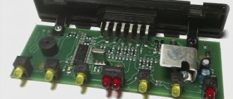
The introduction of standards for the car radio connector, called the ISO connector, allowed car owners to change car radios from different manufacturers without having to cut and connect the wire in accordance with the diagram of each specific manufacturer. But when replacing an old radio, the pinout of the ISO connector of the car radio may still be useful, and now we will analyze it in detail.
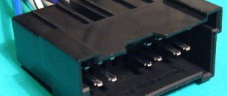
Externally, the ISO standard connector looks like a rectangular connector with eight pins. And there are two such connectors, one connector is needed to power the radio, output the REM wire, power the antenna, etc., and the second is for connecting speakers.
Using the following illustration, we will provide a detailed description of the purpose of each contact:
Markings and types of connectors
Today, all car radio connectors comply with the ISO standard, and two connectors are used. Each is a plug with eight pins, sometimes the manufacturer can combine them into a single housing. Energy consumption sources are connected to one of them; it is marked with the letter A. As for the second, acoustics, that is, speakers, are connected to it. The connector designation is marked with the letter B.
Adapters for car radio connectors
Head units with three outputs can be found on sale, but they are rare and usually represent an exception.
Even if the connected sockets do not correspond to each other, the car owner has several connection options:
- You buy a special adapter for the radio, which can be connected to the outputs of the speaker system.
- The second method is considered “collective farm” among car enthusiasts. Its essence is to cut off the non-standard output and wind the necessary wires to it. But we do not recommend using this option, because eventually the wires will begin to unwind, so the “collective farm” procedure will have to be repeated. In addition, the cost of adapters is not so high to use this method.
Toyota
Adapter from the manufacturer Intro. Responsible for connecting the power supply and acoustic (sound) signal from the ISO connector to the standard radio socket for Japanese-made cars:
- Toyota;
- Lexus;
- Daihatsu.
Renault
ISO adapter from the manufacturer Intro for quickly connecting a modern multimedia system (MMS) or other non-standard device (radio tape recorder) to the place of the factory device. An adapter device of high quality at an affordable price, recommended for installation on cars of the following brands:
- Peugeot;
- Citroen;
- Renaults produced after 2005.
This technical adapter device is a plug for connecting to the standard connector of the player and the connector for the electrical wiring of the car. Without any special tools in a short period of time.
All you need to do is buy an ISO adapter
at an affordable price, and you can independently connect the car radio in the shortest possible time. At the same time, safety from incorrect connections, short circuits and other difficulties is guaranteed.
When you can't do without an ISO adapter
When purchasing a car with medium or higher equipment, the owner receives a standard car radio. Often its functions are limited to playing CDs, MP3 files, and listening to radio stations. The presence of a USB interface is much less common; only premium cars are equipped with a navigation system that allows you to display images from the rear view camera. Unfortunately, not everyone has the opportunity to buy a premium car; in other cases, the car radio is either completely simple or simply absent. The problem is solved by purchasing and installing one of the speaker systems offered on the modern market.
But here an additional difficulty arises - a warranty is provided for a new car, but it is preserved only if the owner adheres to all the rules for operating the vehicle. One of them is not to tamper with the car's electrical wiring. Therefore, many dealers prohibit installing radios and other equipment in third-party service centers. The problem is exacerbated by the fact that many car manufacturers use their own mounts, connectors and form factors, resulting in additional difficulties in installing the speaker system.
Methods for connecting a new radio
If the driver decides to replace the standard car radio, then he has two options:
- Cut off the “original” connectors and twist and solder the wires, and then insulate them. If, after solving the problem in this way, you contact the dealer to take advantage of the car’s warranty service, the probability of receiving a refusal will approach 100%. In addition, in the future it will be difficult to return everything to its original place. It is difficult to expect high quality from the resulting connection - when there is frost outside, the wires become tanned, and the twisting encounters vibration while driving, as a result of which the contact may disappear or periodically disappear.
- Select and purchase the appropriate ISO adapter
. This is the optimal solution to the problem - there is no need to make any changes to the car wiring, or damage the standard connectors. All that is required is to remove the plugs or the “original” car radio, and then install two adapters - for the antenna and for the electrics. This will take no more than 10 minutes! And if the driver has to go to a dealer’s service station, he can always return the standard radio.
The AvtoProfi store offers adapters for various car models. A wide range of adapters will allow everyone to choose the most suitable product that will facilitate the installation of a stereo system. And if you need additional help with choosing a product or making a payment, our employees will be happy to provide it.
A little theory: the pinout of the ISO connector of the radio is determined by the functionality of the contacts in the plugs, in accordance with their numbering. ISO radio connector is a connector for connecting a car's standard radio, certified according to international standards.
When trying to independently replace, for example, a car player from Pioneer with a JVC, car owners are faced with a situation where the wires in the plug are mixed up or do not even fit the shape of the connectors. In order to solve this issue, you need to buy an ISO plug, which is sold at any auto parts store. After that, pinout the head unit connector according to the diagram.
How to connect
To connect the Pioneer car radio, you can use 2 methods.
- Through a standard ISO connector.
- Without using standard connectors.
The first option using ISO connectors is preferable, but it may not be used in all cases. So in some car models there are simply no suitable connectors for connection. If this option is chosen, then there should be no difficulties. In this case, based on the color connection diagram, you need to correctly connect the connectors to the mating parts.
If there are no connectors for connection, you can go in other ways. For single-unit and dual-unit devices, the process for connecting the Pioneer radio will be slightly different.
Connecting 1 din occurs in several steps:
- The decorative panel is removed from its seat using a screwdriver.
- The plugs are removed from the wires, after which the wires need to be connected to the mating ones (a diagram will help with this).
- To protect against short circuits, each connection must be carefully insulated.
- The wires are secured with clamps, which increases the reliability of the overall structure.
You need to connect the Pioneer 2 din radio in a slightly different way:
- If there is no battery wiring in the car, you should use a stranded wire. It is not recommended to use the wires provided in the kit, since their cross-section is not large enough. In this case, the length of such a connection cable must be no less than the distance from the battery to the place where the radio is connected.
- When connecting, do not twist the wires together, as this may cause a decrease in power and interference.
- To properly connect the Pioneer car radio, the wires from the batteries must be connected after completing the assembly of the device.
Scheme
Before connecting the Pioneer car radio using ISO connectors, you should study the entire wiring on the new device. The connectors are a group of contacts (each contains 8 wires).
During installation of the radio, the connection occurs as follows: each contact is connected to the speaker system on one side, and to the power supply on the other side. This system is called pinout of car radio connectors.
Installation of 2 din radio
The situation is somewhat different in the case when a 2 din standard radio tape recorder claims to replace the old radio. The installation procedure for such a radio will be painless if the old analogue meets the same standard. Otherwise, a number of problems may arise.
Firstly, if you replace the standard 1 din standard configuration with 2 din, you will have to replace a number of elements: the center console, frame, etc.
In addition, during these events you will definitely encounter various undesirable phenomena that will not have the best effect on the aesthetic component of the interior of your car.
Based on all of the above, it is quite reasonable to draw one single conclusion: select an audio system that meets the standards provided by the manufacturer of your car.
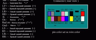
Kenwood radio ISO connector pinout
From this manufacturer (Kenwood) we were able to find several differences in the colors of the electrical wires and their purpose for the upper part of the connector block. The lower one, acoustic, fully complies with accepted standards. In order not to repeat ourselves, by default, the contact and option numbers we missed are also standard, as for all car head units. So, in our opinion, the following changes were minor:
- The yellow electrical wire goes to the car battery.
- The red cable goes to the ignition switch (ACC mode).
- Black braided wire - standard (grounding, ground).
- Blue and white wire - regulate power.
- A wire with a color combination of orange and white – adjusts the brightness of the car radio screen backlight (DIMMER).
Pinout problems
As a rule, no unexpected situations arise when connecting a car player via Euro connectors of the ISO 10487 standard. But only under the following conditions!
Your car is equipped with an ISO connection, both on the radio (a standard output for all global brands of this type of equipment) and on the side of the standard car electrics. This means that the previous owner (the car is not new) was not an experimental electrician, that is, he did not change the wires in the connection box or individual fragments of wires at his own discretion.
If the player was manufactured by someone unknown and where, like the connector itself, in such a situation you will need to arm yourself with a digital tester, brush up on your knowledge of electrical engineering and ring all the contact groups yourself. Based on the measurements, you can determine the power values of the wiring.
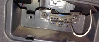
Removing an old car radio
So, the treasured radio is waiting in the wings. It's time to get rid of your old audio system. At first glance, it may seem that this procedure is not complicated. By and large, this is true. However, there are a number of nuances that it is advisable to take into account during dismantling.
Note for you: How to remove a radio without pullers and keys
At the initial stage, in order to avoid damage to the panel elements, it is necessary to find out how the radio is secured in the niche.
Depending on the type of car audio system, there are several mounting methods:
- using flexible metal tongues;
- using plastic clips;
- using a screw connection.
As a rule, if we are talking about a standard radio, there is a last method of fixation. Often, the manufacturer, pursuing an aesthetic goal, masks the heads of screws or screws with plastic caps. Dismantling such a radio should not cause serious difficulties. To do this, it will be enough to unscrew the screws and gently pull it out.
The situation is somewhat different when the radio is located inside a metal casing. In this case, special keys will be required to remove the radio. Hardly anyone remembers their existence when this kind of need arises. However, all radios of the presented type are equipped with them.
The principle of fixing such a radio is not very complicated. Flexible metal tongues with a protruding part are attached to its side walls. On the casing, in a strictly verified place, there are special recesses. The aforementioned tabs go into them, rigidly fixing the radio in the casing.
If you don’t have a key, you can use two thin metal plates to remove it. To do this, you need to insert each of them between the frame and the radio, thereby squeezing out the metal tabs.
After this, you should pull the radio towards you, turning it slightly in different planes. It should be noted that this kind of tricks of manufacturers is nothing more than measures of protection against lovers of easy money.
In addition, radios can be installed in the panel using plastic clips. With this method of fastening, it is important to prevent distortion of the plastic frame. To avoid damage, the clips should be released gradually and evenly, avoiding distortions.
Useful to read: What is a diesel intercooler: principle of operation and causes of failure
With any method of fixing the radio, its dismantling must be done carefully so as not to damage the integrity of the connecting wires and contacts.
ISO connectors as the basis for connecting most radios
So, we realized that the radio may differ not only in appearance, but also in the connectors used to connect it. If these are unique standard radios, then they will probably need their own plug and pinout. If this is a radio tape recorder purchased for an unspecified car model, then it almost certainly has a connection via ISO plugs.
So what are these “almighty” ISO connectors? They look like this if you look at the back panel of the radio.
These connectors come with matching connectors of their own. In this case, in some cases adapters may be used. That is, when the cassette recorder has its own uniquely shaped contact-connectors, but ISO plugs are still installed at the other end
That is why we focused on the fact that the ISO standard for radio tape recorders exists as one of the dogmas! Often you can even find adapters for a specific radio model, be it Pioneer, Kenwood, Alpine, Sony, or even the Chinese Mistery, but they will come with an ISO adapter. Actually, this is a generally accepted and fully formed solution at the moment. After all, you can always switch from ISO standard connectors to the connectors you need, that’s the whole point!
Files for head units (by model):
- 3000U
- 88RS
- AVH-1400DVD
- AVH-160DVD
- AVH-170
- AVH-170G
- AVH-180
- AVH-180G
- AVH-2300DVD
- AVH-2400BT
- AVH-3300BT
- AVH-3500DVD
- AVH-3700DVD
- AVH-3800DVD
- AVH-4400BT
- AVH-5400DVD
- AVH-P900DVA
- AVH-P3100DVD
- AVH-P3200BT
- AVH-P3300BT
- AVH-P3400DVD
- AVH-P4000DVD
- AVH-P4100DVD
- AVH-P4200DVD
- AVH-P4300DVD
- AVH-P5000DVD
- AVH-P5700DVD
- AVH-P5900DVD
- AVH-P6000DVD
- AVH-P6300BT
- AVH-P6500DVD
- AVH-P6800DVD
- AVH-P8400BT
- AVH-X1500DVD
- AVH-X1600DVD
- AVH-X1800DVD
- AVH-X2500BT
- AVH-X2600BT
- AVH-X4500DVD
- AVH-X4600DVD
- AVH-X5700BT
- AVH-X5800BT
- AVH-X7500BT
- AVH-X7800BT
- AVH-X8500BT
- AVH-X8600BT
- AVH-X8800BT
- AVIC-F900BT
- AVIC-HD3 (II)
- AVIC-HRZ099
- AVIC-HRZ900
- AVIC-RZ05 (jp)
- AVIC-RZ200 (jp)
- AVIC-RZ300 (jp)
- AVIC-RZ500 (jp)
- AVIC-RZ700 (jp)
- AVIC-RZ800 (jp)
- AVIC-RL05 (jp)
- AVIC-RL09 (jp)
- AVIC-RL900 (jp)
- AVIC-RW03 (jp)
- AVIC-RW09 (jp)
- AVIC-RW300 (jp)
- AVIC-RW800 (jp)
- AVIC-RW900 (jp)
- AVIC-RZ03 (jp)
- AVIC-RZ05 (jp)
- AVIC-RZ06 (jp)
- AVIC-RZ07 (jp)
- AVIC-RZ09 (jp)
- AVIC-RZ900 (jp)
- AVIC-ZH009 (jp)
- AVIC-ZH77 (jp)
- DA-971
- DEH-30MP
- DEH-50UB
- DEH-88RS2
- DEH-1320MP
- DEH-1400UB
- DEH-1410UB
- DEH-1420UB
- DEH-1500UB
- DEH-1500UBA
- DEH-1500UBB
- DEH-1500UBG
- DEH-1600UB
- DEH-1600UBA
- DEH-1600UBB
- DEH-1600UBG
- DEH-1700UB
- DEH-1700UBA
- DEH-1700UBG
- DEH-2200UB
- DEH-2210UB
- DEH-2220UB
- DEH-2300UB
- DEH-2310UB
- DEH-2320UB
- DEH-2400UB
- DEH-2500UI
- DEH-2600UI
- DEH-2920MP
- DEH-3000MP
- DEH-3050UB
- DEH-3200UB
- DEH-3300UB
- DEH-3400UB
- DEH-4000UB
- DEH-4200SD
- DEH-4300UB
- DEH-4400BT
- DEH-4500BT
- DEH-4700BT
- DEH-5000UB
- DEH-5200SD
- DEH-5450SD
- DEH-6010MP
- DEH-6300SD
- DEH-6310SD
- DEH-6400BT
- DEH-80PRS
- DEH-8300SD
- DEH-8400BT
- DEH-9450UB
- DEH-P40MP
- DEH-P4800MP
- DEH-P55BT
- DEH-P5800MP
- DEH-P5850MPH
- DEH-P6000UB
- DEH-P6800MP
- DEH-P6950IB
- DEH-P7000UB
- DEH-P80MP
- DEH-P85BT
- DEH-P88RS
- DEH-P88RS-2
- DEH-X3500UI
- DEH-X3600UI
- DEH-X5500BT
- DEH-X5600BT
- DEH-X5700BT
- DEH-X6780BT
- DEH-X7500SD
- DEH-X7650SD
- DEH-X8500DAB
- DEH-X8500BT
- DEH-X8600BT
- DEH-X9600BT
- DVH-330UB
- DVH-340UB
- DVH-730AV
- DVH-750AV
- DVH-770AV
- DVH-780AV
- DVH-840AVBT
- FH-X360UB
- FH-X700BT
- FH-X720BT
- MVH-07UB
- MVH-07UBG
- MVH-150UB
- MVH-150UI
- MVH-160UI
- MVH-170UB
- MVH-170UBG
- MVH-170UI
- MVH-570AV
- MVH-580AV
- MVH-1400UB
- MVH-7300
- MVH-8300BT
- MVH-AV170
- MVH-AV180
- MVH-AV190
- MVH-AV270BT
- MVH-AV280BT
- MVH-AV290BT
- MVH-X360BT
- MVH-X460UI
- MVH-X560BT
- PI-703
- PI-803
- SPH-DA100
- SPH-DA120
When purchasing, your car may already be equipped with this device, but its functionality may not fully satisfy your needs or the characteristics of the multimedia system may not be sufficient. Also, the car radio in the car may not support some functions that are important for the owner, such as GPS navigation. Take care of your comfort, let this technique help you cheer up and enjoy a comfortable trip.
A good solution would be to buy a Pioneer car receiver, since this brand is distinguished by its quality, ease of use and high functionality. The pioneer car radio whose instructions are on our website has won its recognition among users not only due to its high quality, but also to its beautiful stylish design. Its appearance is very stylish and it looks beautiful in the interior of any vehicle. The trip will be not only pleasant for you, but also joyful.
Before you start using your car audio system, be sure to read the service manual for its operation. The manual will help you quickly master all the functions of the device, its capabilities and settings. Thanks to the correct and careful use of this device, the equipment will last as long as possible without significant breakdowns.
If for some reason your user manual was lost or you purchased a used device without a manual, do not worry, we will help you find any manual for a car tape recorder of this brand. Our website has a huge selection of manuals for such equipment, and you are sure to find what you are looking for.
Wire marking
Before you connect the Pioneer radio, find out what functions each of the wiring performs. Included with the device is a pair of ISO connectors for connection, each of them consists of 8 pins. The 1st is for the power supply, the 2nd is for the sound reproduction system. It happens that the car does not have the required port. In this case, disconnect the ISO, then connect using mechanical twisting. Multi-colored electrical wires are easy to identify. Each of them performs its own functions.
Purpose and connection of wiring
- Yellow. For batteries, supplied through a fuse.
- Red. Connects to the ignition. Red and yellow cannot be connected to each other, as the battery will quickly discharge.
- Black. Negative, it is fixed to the car body.
- White and blue. They come from the antenna, subwoofer and amplifier.
- Gray. For the right column (positive terminal). The gray wire with a black stripe is connected to the same speaker (minus terminal).
- White. It is connected to the positive terminal of the front left speaker, and the white one with a black stripe is connected to the negative terminal.
- Green. It is connected to the positive terminal of the left rear speaker, green with a black stripe - to the negative terminal.
- Violet. For the rear right column (plus), with a strip - minus.
Connection nuances
I think no one will have any problems or difficulties in removing the stock radio. There is an instruction manual and a number of videos online that can help you do the work step by step.
There is no point in describing the removal and installation procedure, since each machine has its own dismantling nuances. But most often 2 din are installed:
- to Granta;
- Ford Focus;
- Lada Kalina 2;
- Kia Rio;
- VAZ 2110;
- Lada Largus;
- Lada Priora;
- Renault Logan;
- Renault Sandero;
- VAZ 21099;
- VAZ 2114;
- Nissan Almera, etc.
If you have a regular radio, you can easily replace it with more functional and multimedia-rich 2-din equipment.
The manual included with your Chinese radio contains clear and detailed operating instructions.
To make it easier for the user to connect, there is also usually markings on the rear panel of the device for the nodes and required connections.
Practice shows that the main difficulties when installing 2 din arise for those who are engaged in such activities for the first time. Moreover, the most difficult thing is to correctly connect the electrical wiring, find the necessary connectors and combine the new radio with the existing contacts. But if you know the pinout and understand where roughly what is inserted, it won’t be difficult to figure out the connection. And the main element in this matter is a connector called ISO.
It is he who is the main character in the issue of installing a Chinese double-din radio on a car.
ISO connector and pinout
How exactly you will install the new radio in the cabin directly depends on the design features of your car. But all machines in this matter are similar in that an ISO connector is required to connect 2 din.
We are talking about 2 plug boxes (A and B). In some cars, the boxes are combined, but are still divided into 2 sections. Moreover, each section has 8 contacts. The first box or section serves as a power connection plug for the equipment (our Chinese radio), and the second box or section B is used for car acoustics.
Let's start with the first section. It has 8 contacts. The pinout here is as follows:
- 1 contact is not used;
- 2 contact is not used;
- 3 like the previous ones;
- 4 yellow cable is the power cable and goes to the battery;
- Pin 5 in the form of a blue wire leads to amplifiers and an external antenna;
- Pin 6 is an orange cable responsible for the backlight;
- Pin 7 is red and goes to the ignition;
- Pin 8 is painted black and this is our mass.
As you can see, everything is quite simple and clear
It is only important to have instructions and a pinout diagram on hand
There is nothing complicated about the next block or section B, just like in the case of A.
- Pins 1 and 2 in the form of purple and purple-black go to the plus and minus on the right rear column;
- Contacts 3 and 4 are gray and grey-black. This is the plus and minus on the front right speaker, respectively;
- Contacts 5 and 6 are available in white and white-black. Here we are talking about connecting the front left to plus and minus;
- Contacts marked 7 and 8 are made in green and green-black wire colors. Responsible for plus and minus on the rear left speaker.
When you make the connection, be very careful not to mix up the wiring contact groups. Otherwise, you risk not only the sound quality, but also the integrity of the entire car radio. And sometimes even all the electrical equipment in your car.
Thanks to everyone who is with us! Subscribe, ask questions, leave comments and invite your friends to join us!
54,60
Pinout of connectors by wires
Standard pinout of connectors when connecting via wires. To connect the radio in case of loss or breakage of the plug, simply remember or label each wire separately. You can find the correct pinout of the radio installed in your car on the Internet and download it as a picture.
Car radio pinout
Standard connectors used in cars such as Ford, Nissan, Toyota and many other foreign car brands use a 16-pin ISO connector of the European standard, which you can see in the photo below. Such connectors are often made double two by eight, which greatly simplifies the disconnection and connection of the head unit.
Manufacturers in European countries have adopted this connector as the basic one and have adopted the name FAKRA since 2000. A large number of signals are transmitted through such a connector, such as information about ignition, lighting, and speed. With the introduction of more and more functions into the car radio, the Iso connector for the radio changes over time and the pinout increases. For example, Ford, Nissan, Mercedes-Benz, Peugeot, Volkswagen and other European cars began to use a 40-pin connector called Quadlock.
Quadlock
This connector consists of 16 flat legs with additional connectors for other equipment. Auxiliary connectors are made in such a way that it is impossible to mix them up when connecting. It also includes a 12-pin plug for outputting audio signals and a 12-pin plug for inputting signals from various sources.
How to use the head unit
The service manual is freely available on the website. Go to the website and make sure that any manual can be downloaded to your computer or tablet without spending a lot of time and effort. You can find any instruction manual on our huge portal of manuals and manuals. Use the search on the site to find the necessary manual or guide that will help you master the functions of this equipment and its additional capabilities. Enter the name of your model and go to the page with your model, where you can download the PDF file for free.
The manual you need will be presented in PDF format, click on the PDF file icon. This file contains complete information about your device, its functionality, how to properly care for it, etc. Then save the file on your computer as “PIONEER car radio instructions for use” or save your document on your desktop for easy viewing.
Thus, downloading any Pioneer brand manual on our website is very easy and simple. You do not need to register on the site or send SMS messages, just take a few steps, and the ready-made operating instructions for the PIONEER radio will be on your computer.
To ensure that the car radio in your car serves you for a long time, without breakdowns or failures, do not ignore the manuals for your equipment. Only correct operation will help to avoid problems, and will delight you with its impeccable work for a long time.
The service manual will help you not only master the operating rules of the device, but also learn all its functions that you might not even know about. And also, you will learn about what rules must be followed in order for the device to last as long as possible. The PIONEER car radio, instructions for use of which can be quickly downloaded on the website, will delight you for decades, provided that it is used correctly.
The PIONEER car receiver manual, which is available in PDF format, is quite popular among motorists. Beautiful design, rich functionality and high quality make the device of this brand more and more attractive to customers of car dealerships. We hope that we were able to help you find the necessary manual for this vehicle.
Pinout of a standard Euro connector
The Euro connector is a standard plug for many modern devices. An ISO plug is installed on the machine, thanks to which it becomes possible to connect any model of radio with the appropriate connector.
Standards 1DIN and 2DIN
The difference between the standards lies in the size of the devices: a 2-din device is 2 times higher than a 1-din device.
The most common are 1-DIN radios, because Installation of higher devices due to the lack of a seat of appropriate size on the front panel of the car is not possible in every car.
There are 2 types of radio tape recorders:
- With proprietary connector. You need to choose a product whose pinout matches the desired car.
- With universal connector. The device connects directly to the ISO socket provided in the car.
Pinout is carried out according to ISO 10487 standard.
Upper power connector A
The connector serves as a connector between sources and consumers of electricity from the on-board network.
Plugs 1, 2, 3, 6 are rarely used in radio circuits of the lower and middle price segments. The elements are used when connecting additional options in higher quality player models. Wire colors may vary.
You should understand the purpose of the contacts:
- ANT. Used with a retractable antenna.
- Remote. Designed for connecting external amplifiers. Thanks to it, you can increase the number of mounted speakers, which is necessary in the interiors of large cars.
- Illumination. Adjusts the brightness of the player screen (the higher the driving speed, the less intense the backlight, so as not to distract the driver).
- Mute. Adjusts the sound of the device.
- A4. Turns the audio system on and off.
This connection scheme allows you to protect the battery from discharge, because turning on the system is possible only when you turn the ignition key, while the acoustic cascades consume electricity even when turned off.
The pinout of the ISO connector of the radio (European) looks like this:
- Connector A5 (blue) is for the antenna. If the permissible current value (300 µA) is exceeded, both the amplifier stages and the entire head unit may break.
- Wire A7 (red) is intended to power the head unit. When it is disabled, the settings are returned to factory settings. Voltage - 12 V.
- Cable A8 (black). Responsible for connecting the speaker system to the car.
To protect the audio system, the wires must be equipped with a fusible link. If interruptions occur in the operation of the player, you should place a capacitor between connectors A7 and A8, which will act as a filter, smoothing out fluctuations in the electrical circuit.
Bottom speaker connector B
The speakers are connected through it as follows:
- Rear right + (purple).
- Rear right - (black and purple).
- Front right + (gray).
- Front left - (black and gray).
- Front left + (white).
- Front left - (black and white).
- Rear left + (green).
- Rear left - (black and green).
Most devices are designed for 4 channels; 8 wires are used for this (2 pieces per speaker).
The sound quality of the system depends on the “flattening”. If you mix up the connectors, the device will not fail, but the radio will not work correctly.
Audio system elements should be connected with cables with a cross-section of 1.5 mm or more. Thicker wires are used on power lines.
Standards 1DIN and 2DIN
The differences between them are the height of the radios. The number 2 in the designation of the 2DIN standard indicates that the height of a double-DIN receiver is 2 times greater than a device made according to the 1DIN standard. The latest radios are now the most popular and widespread. Installation of double-din radios is not possible in every car, since an appropriate seat must be provided on the front panel.
All car radios are divided into two types: with a proprietary connector, most often made in the form of a plug, and located on the rear wall, and with a universal ISO connector. In the first case, you should purchase a proprietary connector for the radio, the pinout of which matches the desired model. If the machine has an ISO socket, then the other end of the proprietary cable should also have an ISO plug. In the second case, the radio is connected directly to the ISO socket located in the car.
When replacing the radio with another one, you should look at the back wall and determine which block is located there. After this, you can decide whether to purchase a proprietary plug or you can connect the device to the machine through an already installed ISO socket. The pinout of the car radio connector is carried out according to the ISO 10487 standard.
Possible problems and their solutions
The first problems may arise during the installation of equipment. If the radio does not fit completely into the landing shaft, then you should check the possibility of placing the housing in the instrument panel. Some cars require trimming of the internal structural elements into which the plugs or the rear wall of the device rest. The defect occurs due to jamming of the side latches (deformation or dirt ingress).
When using the device, there may be loss of sound from the speakers due to poor contact in the connecting cables. To restore functionality, you need to disconnect the plugs, inspect the connection points and reconnect the Pioneer radio. The defect occurs when the channels of an external amplifier break down; it is recommended to connect the speaker directly to the player. The damaged amplifier is repaired in a specialized service.
Doesn't turn on
If the head unit does not turn on when you press the keys, then you need to turn off the ignition and check the correct operation of the power circuits and the reliability of the cable connections, as well as the connection diagram of the Pioneer car radio. If you use an infrared remote control to start, the transmitter may not work due to dead batteries. Additionally, it is worth checking the functionality of the buttons; if dirt or moisture gets on the contacts, the transmission of signals that control the operation of the audio player is disrupted.
Doesn't turn off
Some Pioneer radios have an original operating algorithm that does not allow turning off the power when the demo mode is active. An attempt to turn off the equipment puts the player into demo mode, which is turned off by removing the front panel. After disabling the function through the menu, pressing the button turns off the power to the head audio unit (except for memory support).
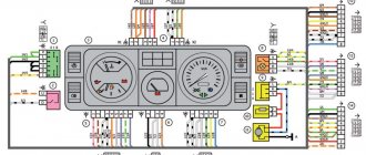
A car radio, head unit, is a multimedia component that provides a single system interface for various media components. The head unit is central to the sound system and is usually located in the center of the dashboard.
Audio
Front speakers
Having configured the radio receiver, as well as connecting sound sources, you can focus on sound quality.
- After adjusting the volume, press the knob to get to the settings menu.
- Here they look for the “Audio” item.
- By pressing the handle, you enter this menu.
- After looking through it, they find the Fader instruction.
- Click on the knob to get to this submenu.
- As usual, select the Fader menu (it should blink).
- Turn the knob and set the value to 15 units.
- Swing the knob to the left once to return to the “Audio” menu.
- Now you need to find a high-pass filter - HIGH PASS FILTER (HPF).
- Included in the menu.
- On the screen, most likely, the HPF is also zero.
- Twist the handle and set it to 50.
- Swing the handle to the left to exit the menu.
Rear speakers
The front speakers work cleanly, now it’s time to switch the rear speakers on the shelf into subwoofer mode - fortunately Pioneer can do this too.
- Turn off the radio.
- Press and hold the power button (as if you were going to set up the “demo” mode).
- Once in the menu, look for the inscription in the form of SW Kontrol.
- By pushing down the handle, you enter this menu.
- By rotating it, the parameter is set to SW.
- Confirm by pressing the handle again.
- Press the power button to save parameters and exit the menu.
- Then they return to the “Audio” menu (press the volume knob and rotate to select).
- By pressing the handle, you enter the menu.
- Here they look for the inscription SW SETTING1. Click on the handle to enter.
- Of the three options presented in the menu, you need to choose one of two - Normal or Rev.
- Having chosen, swing the knob to the left - return to “Audio”.
- Turning the knob clockwise will highlight the SW SETTING2 menu.
- They enter it by pressing the handle. The factory setting will show 80 HZ 0. Rotate the knob to decrease the first value.
- Having chosen what you want, swing the knob to the right to change the second parameter. This is the power level. The range here is from minus six to plus six. It will not be possible to give optimal parameters - it all depends on the quality of the speakers used.
- Press Band to exit the menu.
Before moving on to the next settings, check at different volumes how the selected settings work. If you don’t like something, repeat the steps described, trying other values.
Loudness compensation
This option is hidden in the same “Audio” menu.
- Enter the menu, find the Loudness parameter.
- Select by pressing the knob.
- There are three values available here - High, Middle, Low (respectively high, medium, low).
- This parameter is responsible for adjusting frequencies at low volume levels. It is also impossible to give optimal settings here - they are set experimentally.
- Swing the knob to the left to go to “Audio” or from settings by pressing Band.
Equalizer settings
For advanced music lovers, here are a few more equalizer settings. They are hidden in the same “Audio” menu.
- Once in the menu, rotate the knob to select the EQ SETTING parameter.
- Enter this menu (depending on the model, you may need to enter another menu here). The three parameters offered in this menu are responsible separately for the settings of the low, mid, and high frequencies.
- Set according to your preferences. On some models, you can select several preset settings here. Depending on the speakers and your own preferences, adjust these parameters.
The settings here are no different from others - select by pressing, change by rotating, going to a higher level by swinging the knob to the left.
Sound settings
In order for the radio to play juicily and reproduce low frequencies well, you need to adjust the equalizer curve and adjust the cutoff of low or high frequencies. The equipment supports adjusting the sound balance between speakers; there is a separate function for dynamic bass boost (BASS BOOST).
The sound quality is affected by the bitrate of audio recordings stored on laser discs or removable storage devices. If the recording quality is low, it is impossible to correct the sound picture using the settings.
Equalizer
Equalizer curves with standard parameters are stored in memory; to select the required value, use the menu (EQ Settings subsection). Radio tape recorders support creating your own sound picture by recording parameters in a separate memory cell.
High and low pass filter subwoofer
Setting up the slice is done through the menu, where you need to find the Crossover parameter. The function is supported only by some equipment; the setting algorithm depends on the modification of the acoustic device. Some models allow you to set individual characteristics for each speaker. The cutting height is selected from the list of suggested values.
What can be improved
Speaking of settings, it is worth clarifying that Pioneer regards the concept of a radio tape recorder not just as a device for listening to radio or recordings. In this device you can see the date, time and much more if they are configured. Information can be presented in several languages - either Japanese (since the brand is Japanese in origin), or, more often, English.
Whether there will be Russian on the menu depends on many factors, but even the English menu is easier to understand than the Japanese one. Some additional features, such as USB ports, will also need to be enabled through the menu. Not to mention the above problem of connecting specific speakers.
Markings and types of connectors
Today, all car radio connectors comply with the ISO standard, and two connectors are used. Each is a plug with eight pins, sometimes the manufacturer can combine them into a single housing. Energy consumption sources are connected to one of them; it is marked with the letter A. As for the second, acoustics, that is, speakers, are connected to it. The connector designation is marked with the letter B.
Head units with three outputs can be found on sale, but they are rare and usually represent an exception.
Even if the connected sockets do not correspond to each other, the car owner has several connection options:
- You buy a special adapter for the radio, which can be connected to the outputs of the speaker system.
- The second method is considered “collective farm” among car enthusiasts. Its essence is to cut off the non-standard output and wind the necessary wires to it. But we do not recommend using this option, because eventually the wires will begin to unwind, so the “collective farm” procedure will have to be repeated. In addition, the cost of adapters is not so high to use this method.
If the car radio is without a plug
Pinout of car radio connectors
If the vehicle does not have ISO connectors for car radios, the car owner can install them himself. To do this, pinout is performed in the following order.
- If the plug is missing only in the car, you need to purchase an ISO connector from a specialized store. It must match the plug on the head unit that will subsequently be installed. If the plug is missing from the radio (in its place there is a bundle of wires), then you need to select a block.
- The first to be separated are the wires responsible for supplying voltage. Most often, they are distinguished by an increased cross-section and insulation in red and black colors. You can verify the correct choice using a test device.
- Separate the wires for the speakers according to the car's electrical diagram. During the connection, it is prohibited to connect the negative wires to the common line or ground.
- Separate the wire necessary for the antenna to operate.
- After the linear outputs on the radio are designated, they are connected to the rods of the new connector. To do this, the bare ends of the wire are secured with a crimping tool. This technique ensures reliable fastening.
- After connection, you should check the functionality of the device.
What is iso, iso connector and pinout
So, ISO (in Russian reading - ISO). Abbreviation of the International Organization for Standardization. The organization was created in 1946 to determine uniform technical standards for goods and services (except electronics and electrical engineering) and their certifications.
A connector is an electrical device for mechanically connecting (disconnecting) electrical circuits. By the way, it is not entirely clear why such a connection is marked as iso. After all, as we just mentioned, the standardization of products from the electrical engineering group is carried out by the IEC (International Electrotechnical Commission).
Pinout (Russian version - pinout). The word comes from the English “pin”, which means contact, output. It follows from this that pinout is a description of connector pins in electrical engineering. Information on pinout can be presented in the form:
- scheme;
- tables;
- verbal description (which we will use in the future).
Having finished with the definitions, we move on to the main topic of this article - connecting the ISO connector of the radio.
Features of ISO connectors
Having a single ISO connector standard (electrical characteristics), many automakers, as well as audio equipment companies, can change its external shape at their discretion. That is, if you decide to replace an outdated Hyundai radio with a Mystery multimedia system, first of all, pay attention to the matching iso connection formats.
Also, when installing equipment, you can quite often encounter slight changes in the pinout colors of electrical cords from the standard pinout. Next, we will provide visual descriptions of the pinout of the ISO connector of a standard sample and for individual brands of sound-reproducing equipment (pinout of the ISO connector of the Prology 1715t radio, etc.). Judge for yourself how different they are from each other.
An alternative to ISO connectors are Fakra connections.
Connecting Pioneer to the multifunction steering wheel
If you need to install a non-standard radio in a car with a multifunction steering wheel and not lose control from its buttons, use an adapter. They are universal and specialized for specific brands. Look in stores for an adapter for a multifunction steering wheel. Its connection is carried out as follows:
- disconnect the battery from the car’s on-board network;
- remove the standard radio and pockets, if any;
- find the ISO connector for connecting the car radio - the adapter will be installed in it;
- connect the adapter cable (supplied with it) to the radio, and the adapter itself to the ISO connector of the car;
- configure the steering wheel buttons;
- reconnect the battery to the network.
Video: connecting the Pioneer radio to the multifunction steering wheel via the Zexma adapter
Connecting Pioneer is a simple matter if you follow the rules described above. Disconnect the battery, watch the colors of the wires and you won't have any problems.
Purpose of contacts of the Euro connector in the Pioneer radio
After some time, after purchasing a new car, drivers have a desire to change the radio installed by the factory with a more functional “Pioneer”. And when replacing, you may encounter inappropriate pinouts of the radio's Euro connector by color. Or even with the connector design itself.
Car radio connector plug
In this case, it is possible to connect the radio to the Euro connector via an adapter and pin it out according to the diagram. Since the latest car radios are already available with a standard rectangular ISO connector, there shouldn’t be any difficulties.
Pinouts for various brands of cars and radios
Before getting started, read the instructions for the receiver, and also pay attention to the markings and features of the product itself. The pinout of radios is influenced by standard connectors in different cars.
Pinout diagram for ISO connectors for pioneer radios
Connecting the acoustics of this well-known brand, which is popular among motorists, has some features. Be sure to read the installation manual before starting work. Installation is simple, the main thing is to understand the purpose of each color. In addition to the instructions, the kit includes two “chips” with 4 pairs of contacts: for power and acoustics.
The pinout of the plug has 10-20 outputs, the functionality of each connector varies depending on the model. The KEH series is characterized by the following circuit: No. 1 - antenna, No. 2 - ignition, No. 3-6 and 8-11 - amplifiers. To avoid confusion, please read the instructions carefully.
In order not to burn out the acoustics, before connecting the speakers you need to connect the radio, check that it lights up and switches.
toyota
The pinout of acoustics of this brand is carried out according to standard diagrams. It is optimal to choose a power supply system from a battery, in this case there is no risk of its discharge.
ISO connector:
| № 1 | A+ |
| № 2 | GND |
| № 3 | BAT+ |
| № 4 | Backlight |
| № 5 | Antenna |
| № 6 | Speakers (RR+, RR-, RF+, RF-, LF+, LF-, LR+, LR-) |
sony
When connecting the radio, standard circuits are used.
| № 1 | ANT |
| № 3 | L.R. Line output |
| № 4 | GND. Line output |
| № 5 | R.R. Line output |
| № 6 | CD–LCH |
| № 7 | CD - GND |
| № 8 | CD–RCH |
| № 9 | CD - Reset |
| № 10 | CD – CD clock out |
| № 11 | CD – DSPL select |
| № 12 | CD – data out |
| № 13 | CD – clock in |
| № 14 | CD – data in |
| № 16 | A+ |
| № 17 | GND |
| № 18 | ANT GND |
| № 22-27 | Speakers (LF-, LR+, RF-, RR+, LF+, LR-, RF+, RR-) |
| № 28 | Mute |
| № 29-30 | Speakers (LF-, LR+, RF-, RR+, LF+, LR-, RF+, RR-) |
| № 31 | ANT CONT |
| № 32 | CD ACC Constant |
| № 33 | AMP Constant |
| № 34 | BUP |
nissan
Universal connector:
| № 1-6 | Speakers (LR+, RR+, LR-, RR-, LF+, RF+) |
| № 7 | A+ |
| № 8 | Backlight |
| № 9 | BAT+ |
| № 10 | Speakers LF- |
| № 11 | RF speaker |
| № 12 | Antenna |
| № 13 | GND |
honda
All models of car radios are equipped with a universal European plug for connection to the socket.
| № 1 | Speaker RR+ |
| № 2 | Speaker LR+ |
| № 3 | Backlight |
| № 4 | BAT+ |
| № 5 | A+ |
| № 6 | Antenna |
| № 7-10 | Speakers LF+, RF+, RR-, LR- |
| № 13 | GND |
| № 14-15 | Speakers LF-, RF- |
bmw
Standard European pinout.
| № 1 | A+ |
| № 2 | BAT+ |
| № 3 | GND |
| № 4 | — |
| № 5-12 | Speakers RR+, RR-, LF+, LF-, RF+, RF-, LR+, LR- |
alpine
Alpine TDE-7823W: 1 – BAT+,
| № 2-5 | Speakers LR-, LR+, RR-, RR+ |
| № 7 | Amplifier |
| № 8 | Antenna |
| № 9 | GND |
| № 10-13 | Speakers LF-, LF+, RF-, RF+ |
| № 5-12 | A+ |
mitsubishi
All models use standard European speaker pinout.
| № 1-2 | Speakers RR+, LR+ |
| № 3 | Antenna control |
| № 4 | Backlight control |
| № 5-8 | Speakers LF+, RF+, RR-, LR- |
| № 10 | A+ |
| № 11 | BAT+ |
| № 12 | Backlight control |
| № 13-14 | Speakers LF-, RF- |
| GND |
Video: “deep” settings menu + disabling DEMO mode + disabling time
Turn off the demo
To disable the demo mode, turn off the car radio, and then turn it on again by long pressing the SRC button (maybe the SOURCE button), after which we get to the start settings menu, where using the joystick or the right-left buttons we find the DEMO ON sub-item, and then change it parameter to OFF.
How to adjust the bass
To adjust the bass level, you need to switch the rear speakers to subwoofer mode, which is described in detail in subparagraph 1. Also, to obtain richer bass, correct adjustment of low frequencies through the equalizer, as well as activation of the BASS BOOST function, which is disabled by default, can help. To do this, turn off and then turn on the radio using the SRC (SOURCE) button, and go to the preset menu, where we look for the BASS BOOST sub-item, after which we activate it.
Depending on the Pioneer audio recorder used in the car, there may be other parameters, which you can familiarize yourself with by carefully reading the instructions for the device, which is included in the kit or can be downloaded via the Internet.
Adapters for different connectors
The elements are designed to connect the car radio to the car's electrical network using various plugs. Often, adapters are equipped with ISO connectors on one side, and on the other, a non-standard proprietary connector suitable for a particular car model.
Using such elements, you can mount speaker systems with Euro connectors instead of devices with original plugs, and there is no need to re-solder the conductors or any other intervention in the machine’s electrical network. On sale you can find products with 2 non-standard plugs.
Sometimes the car is not equipped with connectors, then you need to connect the plug suitable for the radio to the wires in the car. This is done both by twisting and soldering. A terminal block is also used for this purpose; additional insulation is not needed in this case. When twisting and soldering, you will have to use cambrics or heat-shrink tubing to ensure safe use of the device.
Adapters are used to connect:
- nutrition;
- antennas;
- radio;
- sound.
The advantage of using the elements is that there is no interference with standard wiring: the user does not have to solder or cut wires.
On devices with the option of control from the steering wheel of the car, a button adapter is provided - another type of adapter. It is a special device with which you can replace the standard audio system with other equipment.
Functions
- Advanced Remote Control App (Pioneer ARC). The app turns your compatible iPhone or Android smartphone into a powerful touchscreen remote control that lets you easily control and customize your compatible Pioneer car stereo's features.
- Compatible with Android. Connect and play music on your device without any apps
- USB input. Connect any device with a USB interface cable to charge your device or enjoy clear, crisp audio.
- 5-band Graphical EQ. Adjust the audio output to adjust playback to suit your preferences.
- FLAC. Ability to play FLAC lossless digital audio files in the car using a dedicated CD-quality output without the need for conversion.
Wiring diagram for radio ND3T W55
As practice has shown, the wiring diagrams for connecting the wires to the ND3T W55 radio are slightly different and consist of two rows of connectors.
Also, Toyota car radios have two power wires, with the yellow wire connected to the main power, and the red wire to the lock. Black is negative and connects to the car body for ground. The blue wire is responsible for the amplifier and antenna. The speakers are connected in pairs with wire, just like in the standard circuit.
The simplest connection diagram for ND3T W55: The yellow and red wires are connected and connected to the battery.
This method is not suitable for a powerful radio, because The battery can be discharged in literally 2-3 days.
For a more powerful radio, a manually controlled circuit is suitable, which is distinguished by an additionally installed additional button to turn off the device.
The third scheme is considered individual. The yellow wire connects to 12V. Red is connected to the side lights. This circuit makes it possible to turn on the radio without ignition with the lights on. The same connection diagram is relevant when installing the Duster device, as well as the Lentel GD-4003u. In the latter, the ISO connector also has an orange wire for connecting to the side lights.
Pioneer DEN MVH-150UB
Basically, connecting the Pioneer DEN tape recorder is similar to the standard algorithm. MVH-150UB is a device adapted to any car that has a landing pocket.
Pioneer DEN has the same settings. The only difference here is in appearance - in the shade of the backlight. You can see the difference in the photo. Settings are saved even if the battery is disconnected. There is a connector for connecting a regular phone or Android.
Radio tape recorder Pioneer 150UBEvery car radio comes with instructions. In it you will find detailed information, photos and a diagram without mistakenly connecting the sound system. And with the right approach, connecting the car radio can be easily done independently.
Also included are two steel plates with eyelets. These are special devices that make it possible to remove the tape recorder from your pocket if necessary. The plates are mounted to the sides of the tape recorder. The lugs are bent with a screwdriver and the panel is closed.
Features of ISO adapters and connectors
The discrepancy between the shape and size of both the ISO output jack on the car player and the adapter plug from the standard car electrical system can hardly be called technical features. Rather, it is a problem and an extra headache for the motorist. The fact is that many manufacturers of audio equipment, as well as car manufacturers, supply their equipment with individually shaped Euro connectors.
Moreover, on different models of the same company, these sockets may differ from each other. But this can be called a global practice. A prime example of this is the discrepancy between chargers between brands and models of cell phones. Moreover, the cost of an ISO adapter for a radio is by no means small. The average price of a good quality device is about 500-600 rubles. Manufacturers are pleased, but what about car owners? There is only one thing that calms me down. Buying an ISO adapter for a Pioneer radio (Sony, JVC, etc.) is not difficult. We will tell you in more detail about some of the features of connecting the ISO adapter for the radio to Ford Focus 2 cars (Cadillac, Chevrolet Aveo T250, Toyota, Renault).
Installation of 1 din radio
Before highlighting the installation features of various car radios, let's take a short historical excursion. The fact is that in the mid-80s, leading companies producing car audio systems came to the conclusion that it was necessary to unify all radios.
In other words, standardize the sizes of the presented devices. Thus, after some time, the so-called DIN appeared, which received the status of an international standard.
The fundamental parameters of this standard are the width and height of the radio. Thus, the 1 din standard corresponds to dimensions of 178×50 mm. 2 din differs only in height, which is already 100 mm.
All of the above information must be taken into account when choosing a radio. Let's look at the case when there was a need to install a 1 din car radio
It is worth noting that this standard is considered the most common. In this regard, difficulties should not arise when installing a new radio. As a rule, the installation of most standard radios is carried out in accordance with the 1 din standard
Let's look at a case where there was a need to install a 1 din standard car radio. It is worth noting that this standard is considered the most common. In this regard, difficulties should not arise when installing a new radio. As a rule, the installation of most standard radios is carried out in accordance with the 1 din standard.
However, a situation may arise when there is a 2 din standard socket in the car console. In this case, when installing a radio that meets the 1 din standard, you will only have to purchase a special adapter frame.
Instructions for connecting the Mystery passive subwoofer to the Pioneer radio
The basic design of low-frequency speakers of both active and passive types is actually similar, except for small additions related to non-active subwoofers.
For this reason, we will analyze the general method with the following configurations.
The process of turning on a car radio with a passive subwoofer is very simple: it is connected directly to the amplifier, which, in turn, is connected in turn to the car player.
The role of the standard amplifier in this circuit is to transmit the signal acquired from the sound of the playback device (car radio) to speakers with high and low resolution frequencies. Where the subwoofer itself acts as a converter of low-frequency signals, and its satellites act as a converter of high-frequency signals.
Due to its rather large dimensions, the installation of the subwoofer is carried out mainly in the luggage compartment of the car and the power supply wires have to be pulled through the entire cabin to which does not improve its (interior) appearance.
Not active subwoofer
You can connect a passive subwoofer to a radio without an amplifier in 4 steps.
- Through the technological hole in the engine compartment we stretch the supply wire to the battery. We install a fuse on the positive (plus) wire closer to the battery.
- We pull the wiring into the cabin and stretch it to the trunk, if possible disguising it under the interior trim parts.
- We insert the wires through the finished technical hole (if necessary, we make it ourselves) into the trunk of the car. And we connect directly to the low-frequency speaker, according to the diagram (on, to -).
Connecting the subwoofer to the Pioneer radio via a single-core power (blue) wire and a wire with tulip connectors
Types of low-frequency audio speakers
Subwoofer is a sound column made for the purpose of playing the improved properties of low frequencies that are not available to ordinary standard audio speakers. Subwoofers are divided according to their types:
The active subwoofer has a built-in power amplifier to remove low-frequency loads from the main amplifier of the car acoustics. Also, its own crossover (a device for dividing frequencies into high, mid, low, etc.), which simplifies the coordination of the subwoofer with acoustics
A passive subwoofer does not have a separate (individual) power amplifier and is connected to standard speakers. Which ultimately negatively affects the sound quality of the car's stereo system and causes additional overload on all output channels. As a result of this, the volume and dynamics of the sound decrease.
What types of car radio connectors are there?
Pinout of ISO connectors for car radios
Not so often, but it still happens that almost every car owner is faced with the problem of do-it-yourself installation and subsequent independent connection of the head unit (car radio) to the standard acoustic circuit of his car. It would seem that this could be confusing, because everything is simple there! Yes, this statement is true. But, as experience shows, this confidence lasts until manipulations with the wires begin, during which the “handy” car owner begins to understand that he urgently needs pinout of Euro connectors for car radios, or even better, complete instructions for connecting the car radio.
What to do if there is interference on the radio from the DVR
Many car enthusiasts are familiar with the situation when, after installing a DVR, interference appears when listening to the radio. A negative impact on sound quality occurs even when the DVR is placed in the cabin in full accordance with the operating instructions.
Radio interference is only possible when the power supply is plugged into the car's cigarette lighter. When the DVR operates autonomously (from a backup built-in battery, if available in the design), such problems do not occur.
One of the possible reasons for radio interference from a working DVR is the presence of electromagnetic radiation from the recorder's power supply and connecting cable. The power of such radiation is small, but given that these components of the device have practically no protection, the effect on the operation of the radio can be quite noticeable.
The appearance of interference is also facilitated by the small distance between the connecting cable of the car DVR and the cable connecting the radio antenna to the radio itself. The wire leading to the antenna is also practically devoid of protection from electronic radiation.
This results in a situation where the DVR's power supply and its cable emit waves, which are immediately received by the antenna and broadcast through the speakers. It is clear that these waves do not carry any information and can only be an obstacle to comfortable listening to the radio.
The driver can try to fix this problem himself. This will require a minimum of parts and certain skills in handling electronic devices.
First, you can try replacing the switching power adapter of the DVR with a linear one. Secondly, either replacement or additional protection of the antenna cable from electromagnetic radiation is required. Shielding the cable will help protect it from extraneous radio waves.
Significantly more complex from a technical point of view is the method in which the DVR is powered not from the cigarette lighter, but directly from the vehicle’s on-board network. The absence of a power supply allows you to get rid of most interference when listening to radio stations. True, few people can install a DVR into a car network absolutely correctly and competently. Therefore, it is better to leave this procedure to specialists.
Another way that can reduce the amount of interference on the radio is to separate the active antenna of the radio and any parts of the DVR that serve as sources of electromagnetic radiation to the maximum possible distance.
If a problem such as radio interference from a working DVR appears, you should not immediately try to make changes to the design of the gadgets (this means replacing the power supply or connecting without using a cigarette lighter). First, you should try less complicated methods, for example, removing the antenna from the recorder or additional protection of the connecting cables.
If the driver does not have proper experience in handling electronic devices, it is better to entrust any work to specialists. Any error can lead to failure of not only the DVR or radio itself, but the entire power system of the car.
In this video, a motorist solves the problem and eliminates the interference.
ravid.ru
Standard form of wiring connections
Upper part of the connector (socket numbers and wiring colors):
- Changing the sound volume when the car is moving - a free-color wire.
- Muting the sound (MUTE) when there is an incoming phone call - a free-color wire.
- Empty nest.
- ACC - power supply 12 volts - wire color yellow.
- Power supply for the radio antenna (12V) - wire color is blue.
- Car radio display backlight - wire color is orange.
- Turning on the ignition - the wire color is red.
- Ground (grounding) - wire color is black.
- Increasing the volume of the right rear speaker - color purple.
- Reducing the volume of the right rear speaker - purple and black.
- Increase the volume of the right front speaker - gray color.
- Reducing the volume of the right front speaker - gray and black.
- Increase the volume of the left front speaker - color white.
- Reducing the volume of the left front speaker - white and black.
- Increase the volume of the left rear speaker - color green.
- Reducing the volume of the left rear speaker - green and black.
The official name of the pinout is ISO 10487 (Euro connector).