Articles
Toyota car radio pinout
The pinout of a Toyota car radio is practically no different from the connection diagram for other car radios. The pinout for Toyota car radios is a circuit consisting of two rows of connectors. Our article will tell you how to connect Toyota devices, what you need to know for this and how to install car radios with your own hands.
Several connection schemes
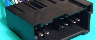
Pinout of toyota car radio connectors
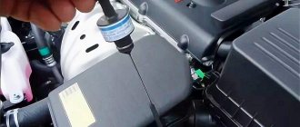
It is believed that the main mistake when connecting Toyota car radios is pulling the positive wire from the cigarette lighter. This will in no way have any effect, since the power of the head unit will drop several times (this is easy to verify if you pay attention to the flashing backlight while the device is operating at high volume). In addition, connecting Toyota car radios through the cigarette lighter will not eliminate sound distortion, which will begin to appear noticeably earlier. On the other hand, in some cases this option may be considered suitable for implementation. The ideal option for connecting Toyota car radios, as well as all others, is to provide the main power supply from the battery. It is advisable to use high-quality wire (it is in no case recommended to skimp on the cable) and be sure to use a fuse, which must be placed as close to the battery as possible.
Note. Let us note right away that car radios have not one, but two power wires. As a rule, yellow is responsible for the main power, red for control (goes to the lock).
Car radio connectors
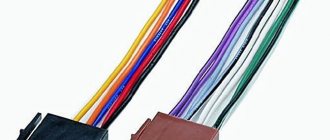
In addition, the pinout of the remaining wires:
- N* – negative wire. They are usually connected to the car body, providing ground. However, it is recommended by experts to connect it to a battery;
- C is the wire that is responsible for the amplifier or active antenna.
In addition, the car radio is also equipped with speaker wires (they go to the rear and front speakers):
- B, C-th – wires for front speakers;
- Z, F – wires for rear speakers.
Ch – black; C – blue; B – white; S-th – gray; G – green; F – purple.
Note. You also need to know that each pair of acoustic wiring contains additional monotonic and negative wires. The latter is often marked with a black stripe over the main color.
Connection according to diagram 1
Connectors for car radios
We do this:
- We connect the power wires to each other;
- We connect them to the battery.
The good thing about this scheme is that it is easy to implement. On the other hand, it is only suitable for car radios with low power consumption. If you connect a powerful device according to this scheme, then in just 2-3 days in sleep mode the car radio will completely discharge the battery.
Connection diagram 2
This circuit is suitable for any powerful car radio:
- We connect the power wires to each other;
- We connect them to the battery;
- We install an additional button (it is responsible for turning the device on and off).
This scheme involves manual control of the radio, but the settings will not go wrong and the battery will not run out in a couple of days.
Connection diagram 3
Connector for car radio
Individual scheme, implying the following:
- We connect the main power wire (yellow) to 12 V;
- We connect the additional one (red) to the side lights (via a relay, the winding of which is connected to the ashtray light bulb).
This scheme provides the following advantages:
- The device turns on simultaneously with the “dimensions” automatically;
- The driver will never forget to turn off the side lights and headlights;
- While stopping, you can listen to music without turning on the ignition;
- If you replace conventional small bulbs with LED ones, the electricity consumption will be very low.
There are many more schemes for connecting Toyota car radios, such as connecting via ACC or via an alarm. As a rule, they are not that common and are not suitable for everyone. In particular, connecting via ACC (lock) is inconvenient because the device will not function without a key in the lock.
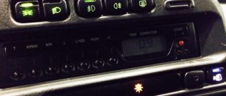
Pinout (pin designation) of terminals on the Toyota Prado 150 radio
Appearance of the radio installed on the Toyota Prado 150.
Model 86140-60150. Similar models can be found on other Toyota cars, say, Venza, the only thing is that the buttons and design of the device will be different.
Now let's move on to the back wall and the output plugs. Here we will provide the main information on our topic.
(picture can be enlarged by clicking on it)
What is iso
ISO is an international organization that develops standards and regulations for various industries. The abbreviation sounds the same in all languages. A Russian manufacturer working in accordance with standards labels its products with the abbreviation “ISO” or “ISO”. All well-known developers of car radios equip their products with two types of standard plugs. Each looks like an eight-pin rectangular connector.
Several connection schemes
Today, one of the main mistakes Toyota owners make is connecting the head unit to the positive cable from the cigarette lighter. This approach will reduce the power of the audio system by at least half. In addition, connecting the head unit to the cigarette lighter will not reduce interference distortion. In any case, the Rav4 radio or any other model should be connected only to the battery and for this you need to use only high-quality wires. In addition, the electrical circuit of the audio system must be protected by a fuse, which should be installed as close to the battery as possible (video author - Redpower Evgeny).
It is necessary to take into account that the standard radio of a Toyota Corolla or any other model can be equipped with not one, but two power cables. Typically, the yellow wire provides the main power, and the red cable is responsible for control, usually connected to the lock.
Below is the pinout of the standard radio:
- N - negative cable, usually connected to the vehicle body, provides ground. Automotive electricians advise connecting it to the battery.
- C - antenna or amplifier power cable.
- B, C - wiring for connecting front speakers.
- Z, F - cables for connecting rear speakers.
Scheme 1
The standard radio of a Toyota Camry V40 or another model can be connected to the vehicle’s on-board network in one of three ways, consider the first:
- according to the diagram, the power wiring must be connected to each other;
- then the cables should be connected to the battery.
One of the main advantages of this Toyota head unit wiring diagram is its ease of implementation. But it should be borne in mind that it is relevant for audio systems characterized by minimal energy consumption. If you decide to connect a powerful radio according to this scheme, then after a few days it may well drain the battery.
Visual installation diagram
Scheme 2
Any powerful head unit for Prado 120 or other Toyota model can be connected using this diagram:
- As in the previous case, the power wiring should be connected.
- Then they need to be connected to the battery.
- An additional button is installed to turn the audio system on and off.
Using this option involves manual control of the audio system, but its implementation will allow you to save the entire configuration, while the likelihood of battery discharge will be minimal.
Scheme 3
Another connection option is implemented in this way:
- The yellow cable connects to the battery.
- The red wire must be connected to the side light circuit section. For this, a relay is used, and its winding must be connected to the ashtray diode.
Another connection option
It should be noted that this scheme has certain advantages:
- the head unit will always turn on with side lighting;
- the likelihood that the car owner will forget to turn off the lights is very low;
- when the car stops, the driver will be able to listen to music without having to turn on the ignition;
- When replacing side light bulbs with diode ones, the system will consume less energy.
In principle, the radio of a Camry or any other Toyota model can be connected using different circuits, for example, from the ignition or through the anti-theft system. But such options are less popular among car enthusiasts, so we will not consider them.
Connecting the camera according to the pinout
Knowing the pinout of the car radio, you can easily connect the rear view camera with your own hands. Using the example of the popular Toyota Ca-Fi device, we will learn how to do this. The process itself is divided into two parts: the actual installation of the device with the connection and the connection of the rear view camera.
Note. Installing and connecting the monitor is no different from installing the factory head unit. You just need to swap the connectors and that's it.
But connecting the camera can be difficult for some. Here's what you need to know:
- The rear view camera for Toyota Prado is powered by 5V;
- To connect it, you will need a connector from the factory monitor, which remains free after installing the new radio;
- This same connector is 14-pin. But we only need two video signal wires and a reverse signal;
- In addition, you will need to convert the voltage from 12V to 5V.
Note. To convert voltage means to carry out the process using a special converter, which is sold in any store.
The camera connection diagram has its own pinout. This is what she looks like.
Pinout of toyota car radio connectors
The circuit is positioned as if you were looking at it from the side of the wires. The photo in the upper left corner is placed for clarity. So, in order to connect the camera to the Toyota car radio, you must first connect together the reverse signal and the Reverse wire on Ca-Fi. In addition, it will be necessary to install a converter and make a tulip for transmitting video data.
Note. This does not mean that you will have to literally do everything from scratch. You just need to buy Scotchlocks in the same store where you purchased the converter (they will help connect the wires to each other).
The photo below shows how to splice wires using tape.
Scotchlock and wires
Next we do the following:
- We start the car;
- We turn on reverse gear;
- Let's check how everything works (the monitor of the installed radio should show the image from the camera).
Thus, knowing the pinout of Toyota car radios, you can connect using any of the selected schemes. During the work process, it is extremely useful to watch a video review. Step-by-step instructions from other sources will also help. The price of installing a car radio yourself is noticeably different from the cost of specialist services, which is several times higher.
Popular:
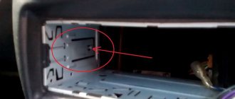
To separate the climate control unit and the radio, connected together by an iron frame, you need to unscrew 6 bolts, 3 on each side. During the day everything is much better.
Next, despite the fact that the camera voltage is designed for a wide range, a simple 12V stabilizer was made. You can buy a ready-made one on the radio market, or maybe you don’t need it at all, anyone can decide for themselves. I won’t describe how to remove blockages from your head; anyone who needs it can find it on secam.
Connecting a reversing camera
Which locks had to be removed: Try it, maybe it will work for someone without turning it off, don’t forget to let me know. And the pinout of the connector When you connect the camera to this connector, the 3rd pin of this connector goes to ground. Ground is on pin 4, so these 2 wires are connected to the 2nd pair of contacts, to the button.
If there is only a haze on the display, this means there is a problem with the video plus, or the camera’s power supply. After making sure that the camera is working, we begin its installation.
Comments:
Remove the rear door trim, then remove the rear plastic frame with the lights. We unscrew the 8 bolts with a 10mm wrench and remove the cable from the door handle.
On the sides the frame is held on by latches; by squeezing them out from the inside, the frame will open, like a book mounted on a binding. We try on the camera and drill a hole for it. If we’re going to create something, then create it using the best experience of others, so I decided to immediately install a washer nozzle looking at the camera.
Therefore, we drill a hole under it, as well as a hole in the door itself, in order to route the wires and washer hose.
Source: nkscooters.ru
Pinout (pin designation) of the terminals on the Toyota Corolla radio
The same thing for another radio, for Toyota Corolla.
Note that if you compare similar plugs for Prado and Corolla, these are CN701-1, CN701-2 (below) and 90980-10997 (above), you can see that they are the same in appearance and functionality of each of the pins and pins. This only confirms our statement that if you have a different radio, with a different arrangement of plugs, but with the same shape, then with a probability of 99 percent we can assume that the conclusions there will be the same as those given here.
Pinout of the original Toyota Rav 4 radio
In order for the pinout of the Toyota Rav 4 radio connector to be successful, you should use the above tips by purchasing either a branded standard radio or adapters that match the connectors.
In this case, the pinout of the Toyota Rav 4 radio is done as follows:
- the gray wire goes to the ACC ignition;
- brown will be responsible for mass (-);
- blue with a yellow stripe is nothing more than a permanent plus that will give the radio a boost, even if the driver turns off the ignition;
- the green wire simply powers the backlight.
By the way, if a motorist is not sure that he can cope with connecting and pinouting a Toyota Rav 4 radio, then it would be best for him to turn to professionals.
Toyota Corolla radio
It is worth noting that Japanese cars, including Toyota 86120-60581, are crammed to the brim with electronics, which often confuses many Russians. In this case, the standard factory-type radio is replaced with a more modern one or connected quite quickly and does not require much experience in this area.
Video “What must be considered when installing an audio system?”
ISO pinout or pinout is the identification of each electrical connection pin in a connector or diagram according to its corresponding numbering and functionality. The speaker system of any manufacturer is connected to the standard ISO connectors of the car. Proper pinout will help you get a good sound at the output and not burn out the connectors with voltage. You can understand the wires using standard diagrams. You can install any brand of car radio without having specialized knowledge in electrical engineering. When working with non-standard connectors, do not forget about safety. “Ring” the wires using a multimeter.
How to properly connect the factory radio of a Toyota Corolla
In order to connect the standard Toyota Corolla radio, it is worth understanding the reasons why the device is being changed.
The fact is that the proprietary Japanese version upsets many because:
- has a crooked FM range;
- reads CDs that were not purchased from company stores rather poorly;
- can shoot CDs quite far;
- The disk reading function in MP 3 mode is completely absent;
- does not accept the flash drive;
- there is a TV available, but it often does not work;
- navigation has maps of Japan or does not work at all;
- inability to repair equipment.
Connecting the Toyota Corolla radio correctly will be much easier than connecting a huge number of wires to connect the MP 3 player. However, it would be better to replace the standard radio from the Japanese manufacturer with a European version for the Toyota Corolla, which can play high-quality video and audio files.
So, connecting the radio to Toyota 86120-60581 is done in stages:
- remove the frame by unfastening the semicircular frame from the clips;
- pry it up with a screwdriver and carefully pull it out towards you;
- you can help yourself remove the knob by piercing the rear holes with a screwdriver;
- unscrew the bolts of the radio;
- disconnect all connectors one by one;
- take out the old radio.
Removing the frame
It is worth understanding that the connectors of the Euro radio will not fit the connectors of a Japanese vehicle, so you will have to purchase adapters. The thing is that the Toyota receiver has a couple of connectors instead of one for some unknown reason.
Before connecting a new unit, it is necessary to correctly pinout:
- blue-yellow wire – to permanent plus;
- green-red – to the ignition switch;
- brown – negative or grounding;
- green – for illumination;
- blue-yellow and purple – left (-) front speaker;
- light green and blue – right (-) front speaker;
- black and yellow – left (-) rear speaker;
- red and white – right (-) rear speaker.
Radio pinout
Features of USB adapters for
It is not convenient to constantly record music and audio books for listening in the car onto discs. It’s easier to use a flash drive and a phone, but the native multimedia system of the Camry V40 does not have such functions, so car enthusiasts install USB adapters.
USB adapter (don't take it as an advertisement)
Advantages of installing an MP3 adapter in Toyota Camry V40:
- You can do the installation work yourself
- the cost of the device is not high
- Steering wheel music control is retained
- The CD changer continues to operate normally.
To install the USB adapter, you need to disassemble the head unit, this process is described above. Next, the MP3 adapter is pinned out, the cord is inserted into the plug of the CD changer at the back, be careful into the 12-pin connector (6+6). The adapter can be hidden behind the stock head unit.
12-pin connector for connecting a USB adapter
It is best to pull the USB and AUX cords into the glove compartment to the farthest hole because the glove box guides move closer to it. To use a USB flash drive (flash drive) in a car, you need to format it in FAT32, create folders CD1, CD2, etc. and record music in MP3, WMA, AAC format. (The number of CD... folders that will be played depends only on the head unit and how many disks it is designed for). Jumping between the standard head unit and the adapter occurs after pressing the “DISC” button. Switching folders on a flash drive is similar to switching disks in a CD changer.
Pros of using an MP3 USB adapter:
- ability to play a large number of songs,
- Each folder can store up to 100 tracks,
- the last played song is saved,
- when started, the song plays from the moment at which it was interrupted,
- AUX allows you to play audio files from any device with a headphone jack.
How to connect AUKS to a Toyota standard radio
Often, motorists try to connect AUKS to the standard Toyota radio in order to make the most of all their capabilities. It is worth noting that the AUKS for Toyota Starlet 56037 is a connector for connecting digital media to it, including a flash drive, MP-3 player, mobile phone or tablet.
AUKS for Toyota standard radio
In order to connect a Toyota AUKS to the radio, you should perform a number of simple steps:
- remove the Toyota Corolla decorative panel;
- disconnect the rear window heating connector;
- remove the gearbox by disconnecting its wires and the ashtray;
- pull out the head unit;
- completely disconnect the connectors and antenna;
- disassemble the receiver housing;
- disconnect the cables;
- After that, to connect the AUKS, you need to solder the wiring to the board.
In order for the AUCS to work correctly, it is necessary to correctly pinout:
- yellow and red wires are needed for channels;
- the black wire is connected to the negative or ground;
- The following should be soldered to the board:
- RCH – red;
- LCH – yellow;
- GND – black.
Connecting the AUX
After this, all wires should be routed through a special hole and connected to the radio. The cable is easily routed through the glove compartment, after which the receiver can be assembled and tested by connecting a phone or flash drive to the AUX cable.
Methods for connecting a camera to a Toyota standard radio
It is also possible to connect the camera to the standard Toyota Starlet 56037 radio in order to constantly be aware of what is happening behind you. At the same time, connecting a rear view camera to a Toyota radio will not be very difficult on your own.
To do this, the Toyota Corolla head unit must go through the pinout procedure:
- connect the wire with the yellow tulip to the rear view camera;
- place the second end of the yellow wire on the standard radio;
- connect the wire with the red tulip to the wire that will give a plus when the selector is in the R position;
- connect the red wire with the terminal that activates the short-circuit breaker to the radio wiring;
- connect the red wire to the positive permanent connector;
- Throw the black wire onto the negative ground and onto the camera.
At the same time, when connecting a rear view camera, you should connect a 12 volt wire to the purple wire of the reverse gear. But the wire that connects the camera can be combined with the one that we throw to ground.
After everything is connected correctly, it is worth debugging the cameras in the radio settings.
You decided to connect the radio yourself, but when you saw the number of wires coming out of it, you were afraid that you couldn’t handle it? In fact, there is nothing wrong with this, and in this article we will figure out how to connect a radio in a car.
Replacing a car radio: instructions
How to connect (install) a Chinese 2 din radio to a car and connector pinout diagram
Replacement should only be carried out with the car engine turned off. In addition, you need to make sure that the future equipment is the correct size.
To replace this device, you need to prepare the following tools:
- screwdriver;
- connection diagram for gu teyes on Prado 120;
- pliers;
- Euro ISO connector adapter.
Now you can start replacing.
The first step is to remove the old device. This procedure is performed like this:
Carefully dismantle the front panel, it is important not to damage the casing. Then we unscrew the screws that attach the product to the body. We put all the unscrewed bolts in a separate box so as not to lose them. Now you need to remove the device from the socket by pulling it towards you. After this, you need to disconnect all connectors from the power supply. We have removed the device, now you can start connecting the Prado 120 radio with an 8-inch touch screen
We have removed the device, now you can start connecting the Prado 120 radio with an 8-inch touch screen.
The connection diagram for the Tesla Prado 150 radio is below.
The connection occurs as follows:
- Using an ISO Euro connector, we connect the positively charged terminal and then the negatively charged terminal.
- We connect the car antenna.
- We insert the body into the frame, the frame into the panel.
- We secure it with screws.
This completes the replacement of the Toyota Prado steering radio. Now you need to check its functionality. To do this, you need to turn on the radio or other audio player.
What can you encounter if your car radio is not connected correctly?
This is not to say that to properly install a radio, you don’t need to have any skills at all. It is advisable to have at least initial experience in connecting electrical devices, but this is not a prerequisite; following the instructions, a person can complete the installation without any experience. To understand whether everything was done correctly, it is worth monitoring the operation of the radio. A sign of an error will be the presence of the following factors:
- The radio turns off when the volume is increased.
- When you turn off the ignition, the radio settings are lost.
- The radio drains the battery when turned off.
- The audio signal is noticeably distorted, especially when listening at high volumes.
In very rare situations, it is not the person who connected it who is to blame, but the seller who sold the low-quality product. Of course, this option cannot be ruled out, but you will still need to double-check the connection diagram.
Size and types of car radios
Universal radios have a standard size, it can be 1 – DIN (height 5 cm, width 18 cm) and 2 DIN. (height 10 cm, width 18 cm.) If you change the radio from large to small (from 1 – DIN, to 2 – DIN), you will need to buy a special pocket that will cover the missing din. In terms of connection, these radios all have the same connector, its name is ISO or it is also called a Euro connector.
Radio size 1 - DIN Radio size 2 - DIN Pocket for installing radio 1 - DIN
Standard radios are installed on cars from the factory and have a non-standard size; in this case, there are two options for installing the radio. The first is the simplest, you purchase the same standard radio and install it, it fits in size and connects to the standard connectors. But the cost of these radio tape recorders is often inadequate. And if you find a budget option, then with 100% probability it will be from China, which is not particularly famous for its sound quality and reliability.
If your 2 din radio has an LCD display, then you can connect a rear view camera to it, and we discussed in detail how to do this in “this article”
Hint for TOYOTA owners. In most cars of this brand, the standard radio has a size of 10 by 20 cm. In this case, you can look for “Spacers for Toyota radios”, they are 1 cm in size and you can easily install a standard-sized radio, i.e. 2 – DIN, to install 1 – DIN you will still need to buy an additional pocket.
Description of the car radio
All standard radio models have a classic operating system designed for Android. This is basically Windows 8 or Google android 7.8.2 (upgradable to Android oreo). This device allows you to get more opportunities. Those. – now the tablet or smartphone has migrated to the radio.
All buttons on the device are touch sensitive. Those. – you can safely replace them at your request. Only the on/off button is non-touch.
Externally the design looks very nice. There is a desire to press each button in turn. But even an inexperienced user will be able to understand the system. Important icons are located on the desktop, but they can be replaced at any time. To do this, just click on any icon and hold your finger for a while. After this, a menu will appear where you can replace one icon with another.
By default, the interface has a set of standard functions that are typical for models of all touchscreen radios:
- uploaded video;
- all downloads;
- downloaded music;
- system settings;
- radio;
- phone (you can receive a signal via blue tooth);
- equalizer;
- software installer;
- browsers (usually Google);
- play market.
Connecting the radio.
There are many cars, and each of them can use its own set of connectors to connect such equipment. Basically, there are three options:
- Option one is the most favorable. You already have a chip in your car to which everything is connected correctly, i.e. All speakers, power wires, antennas are connected to this chip, and everything is connected correctly. This happens but, unfortunately, very rarely. This means that you are lucky, you just connect your brand new radio to this chip, and everything works for you.
- The necessary wires are routed and connected, but the socket on the radio is different from the plug on the car.
- There is no power lead out or it was done incorrectly.
With the first point, everything is almost clear. When the device socket does not match the connector, you will need to use an adapter. Despite the fact that these connectors are most often individual for each model, many companies practice supplying a separate ISO adapter. If there is no adapter or its format is not suitable in this case, you can either purchase such an adapter or twist the wires yourself. Of course, the second step is longer, more complex and riskier. Only technical centers that have experience in such procedures do this, so before you connect the radio in your car in this way, you need to think about everything very carefully.
Adapter for TOYOTAConnecting the ISO adapter - Toyota
If you want to do the twisting yourself, you need to check the correspondence of the wires on the radio and the car connector. Only if the colors match can you disconnect the battery and disconnect the car and audio system connectors.
Connected ISO connectorISO connector
Decoding the color code of wires
I would also like to note that many people install a car radio at home or in a garage using 220V; you can read how to do this correctly “here”
How to properly connect a car radio?
First you need to purchase all the necessary wires. The wires must be made of pure oxygen-free copper and have silicone insulation. The yellow and black wires are power wires, the cross-section of these wires should be more than 2.5mm. For speaker wires and AAC (red), wires with a cross section of 1.2 mm are suitable. and more. Try to avoid a large number of twists, the ideal option is where there will be none at all, because... twists add extra resistance and this negatively affects sound quality and volume.
Connection diagram for radio and speakers
If you want to replace not only the radio but also the speakers, we advise you to read the article “what you need to know when choosing car speakers”
Adapters for different connectors
The elements are designed to connect the car radio to the car's electrical network using various plugs.
Often, adapters are equipped with ISO connectors on one side, and on the other, a non-standard proprietary connector suitable for a particular car model. Using such elements, you can mount speaker systems with Euro connectors instead of devices with original plugs, and there is no need to re-solder the conductors or any other intervention in the machine’s electrical network. On sale you can find products with 2 non-standard plugs.
Sometimes the car is not equipped with connectors, then you need to connect the plug suitable for the radio to the wires in the car. This is done both by twisting and soldering. A terminal block is also used for this purpose; additional insulation is not needed in this case. When twisting and soldering, you will have to use cambrics or heat-shrink tubing to ensure safe use of the device.
Adapters are used to connect:
The advantage of using the elements is that there is no interference with standard wiring: the user does not have to solder or cut wires.
On devices with the option of control from the steering wheel of the car, a button adapter is provided - another type of adapter. It is a special device with which you can replace the standard audio system with other equipment.