The ignition coil in the 8-valve version of the Lada Kalina power unit, as in the 16-valve version, plays a primary role. It allows the engine to start easily even in very unfavorable climatic conditions. This circumstance encourages owners to pay increased attention to this product. Even a minor deviation in the functioning of the coil can immobilize the car for a long time. To minimize the risks of such a situation, we urge owners to follow the manufacturer’s regulatory recommendations. If the owner neglects this aspect, he will provoke himself into replacing the coil, which is very expensive. And in general, the ignition system must be maintained and operated carefully.
Buying new wires
In this section we will describe which high-voltage wires are best purchased for Kalina at a car dealership.
Standard wires from universal parts from AvtoVAZ will cost approximately 500-600 rubles. Set includes 4 pieces. Components for Kalina from early years of production are cheaper - about 400 rubles. High-voltage wires Kalina 8 cells. 50-70 rubles cheaper. Wires from third-party manufacturers, including foreign ones, are available for sale. For example, wires of the “HUCO” brand are distinguished by an increased insulating layer and, accordingly, cost more - about a thousand rubles. A complete ignition wiring harness for a Kalina costs about five thousand rubles in online stores.
Among “Kalinovodov” “high-voltage” brands “SLON” are popular. These products are distinguished by their ductility, resistance to fractures and, in general, have a longer service life compared to factory components at a competitive price - about 700 rubles.
Checking the ignition coil
Ignition coil Kalina 8 cl which is better
There are two reliable ways to check the IKZ: visual inspection and checking with a multimeter.
It should be noted that the IKZ check is similar for all Lada cars with a 16-valve engine, i.e. the check on cars such as LADA Vesta and X-ray will be the same.
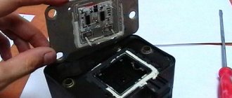
In order to check the ignition coil, it must be removed from the car.
Removing IKZ:
- Disconnect the negative terminal from the battery.
- Remove the decorative plastic trim.
- We unscrew the coil we need with a “10” or Torx E8 head.
- Remove the coil plug and remove it.
Visual inspection
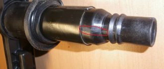
After the coil is removed, it must be carefully inspected. The rubber tip should not have tears or cracks. The plastic part must not be melted or cracked. The contact spring must be in the correct shape without oxidation or rust.
Cracks in the coils or tears in the rubber cap will direct the spark to the engine body, therefore, no current will be supplied to the spark plug, which will lead to misfires.
If such visual faults are detected, the coil must be replaced.
Checking with a multimeter
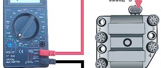
Testing with a multimeter is divided into two stages. Checking the resistance of the IKZ itself and checking the control voltage of the IKZ (checking the voltage on the IKZ power supply block).
Let's start by checking the voltage at the IKZ power supply.
To do this, set the switch on the multimiter to constant voltage.
Turn on the car ignition
On the block in connector number 3 we take a measurement (we connect one multimeter probe to the motor body and the other to pin number 3) the voltage should be at least 12 volts. If the voltage is less, this means that the battery is discharged or the ECU controller is faulty.
Checking the IKZ resistance
In order to check the resistance of the IKZ, you need to use a multimeter. It should be noted that resistance measurements must be carried out on a cold engine, because The resistance of the coil windings strongly depends on its temperature.
To check the resistance, it is necessary to check two windings, the secondary and the primary.
Checking the primary winding of the IKZ
When checking the primary winding of the IKZ, it is necessary to set the resistance readings on the multimeter, namely 200 Ohms. Since the resistance readings on the primary winding are not large, and the error of the device is possible, you first need to find out the error of the multimeter. In order to find out the error, you need to close the probes together, the value that will be reflected on the multimeter screen will be the error.
Next, we connect the multimeter probes to contacts 1 and 3 (the outermost contacts of the IKZ) and obtain resistance readings. From these readings we subtract the multimeter error and get the true value of the resistance of the primary winding.
Ideally, the resistance of the primary winding should be about 1 Ohm, or better yet 0.
In this example, the reading is 1.1 Ohm without taking into account the error; from 1.1 Ohm we subtract 0.7 Ohm to get 0.4 Ohm. Verdict: the primary winding of this IKZ is in working condition.
Checking the secondary winding of the IKZ
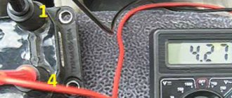
In order to check the secondary winding of the IKZ, set the multimeter to 2000 kOhm.
We connect the red multimeter probe to the spring, and the black one to the middle contact on the IKZ (pin 2). We look at the readings of the device; on a working coil, the resistance of the secondary winding should be in the range of 300-400 kOhm.
As we see, the readings of the secondary winding are also within the normal range. It follows that this IKZ is working.
If the readings are too high, you can try removing the rubber cap and spring from the coil and cleaning the contact patch, then measure the resistance directly again without the spring. If the resistance reading still does not decrease, you should think about replacing the ICP.
The easiest method to detect a faulty ignition coil, without any devices or instruments. This is a reversal of the IKZ.
Determining a faulty coil without a multimeter.
Checking the ICP with a spark gap
Procedure
- Disconnect the IKZ from the spark plug.
- Install a spark gap on the IKZ.
- Apply ground (from the battery terminal) to the spark gap using a wire.
- Turn the crankshaft with the starter.
- If there is a spark, then the IKZ is working.
Let us remind you that you can find a problem in engine operation by independently measuring the pressure in the fuel rail, or by checking the compression in the cylinders.
Keywords: Lada Vesta engine | lada xray engine | Lada Largus engine | Lada Granta engine | Lada Kalina engine | Lada Priora engine | ignition system for Lada Vesta | ignition system lada xray | ignition system Lada Largus | ignition system for Lada Granta | ignition system for Lada Kalina | ignition system for Lada Priora | universal article
8
Found an error? Select it and press Ctrl+Enter..
The most popular configurations of Lada Granta FL have been determined
About audio preparation of Lada Largus or how to install a radio and speakers
How to install the armrest of the rear row of seats on Lada Vesta
Removing the door trim of the Lada Granta
https://youtube.com/watch?v=4wHGBUx6x3M
Custom ignition coil
VAZ 2114: replacing the ignition coil (module)
This coil is installed on a 16-valve engine and is structurally different from the MZ in that it is responsible for the operation of only one cylinder. It is installed directly in the spark plug well and is put on the spark plug.
When it breaks down, the cylinder to which it is directly related fails.
IKZ device
The figure shows a cross-section of the IKZ.
The ignition coil, like the ignition coil, has two windings, a secondary and a primary, between the turns of which a metal core is placed. The coil has a rubber cap that fits onto the spark plug and prevents the spark from escaping to the side onto the engine housing.
Signs of IKZ malfunction
Below is a list of indirect signs, the presence of which can suggest that the ignition coil is faulty.
- The engine is tripping;
- Loss of power;
- Jerks when accelerating;
- Difficulty starting the engine;
- “CHECK ENGINE” lights up;
If such signs are detected, it is necessary to check the ignition coil.
Examination
The check is carried out in two stages: visual and using a device. These two methods will help you accurately verify the serviceability of the IKZ on Kalina.
Visual inspection
Visual damage to IKZ
It is necessary to remove the IKZ from the spark plug well and inspect it carefully. There should be no chips or cracks on the reel body. The resulting cracks can provoke a breakdown of the coil, which can lead to misfire in the cylinder
You should also pay attention to the rubber cap; there should be no cracks or tears in the rubber; these defects will inevitably lead to misfires and spark breakdown to the engine body
If a visual check shows that the IKZ is in good condition, you can begin checking using the device.
Checking with a multimeter
Testing with the device involves measuring the insulation resistance of the secondary and primary windings, as well as its integrity.
Ideally, the winding resistance should be as follows:
- Primary winding: tend to zero;
- Secondary winding: 300-400 kOhm;
So, let's start checking the primary winding. We set the measurement switch of the device to measure a resistance of 200 Ohms. Then we can check the error of the device; to do this, we close the probes of the device with each other and look at the readings of the multimeter; in this case, the error of the device is 0.7 Ohm (visible in the photo).
Determination of instrument error
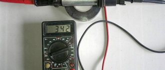
After the error of the device has been determined, we proceed to measuring the resistance. To do this, we connect the multimeter probes to the extreme terminals of the coil (as shown in the picture (Fig. 1), pins 1 and 3) and obtain the resistance of the primary winding (in this case, 1.1 Ohm (Fig. 2)) from here we subtract the instrument error and get the desired value (in this case the coil is working).
Fig.1 (IKZ contacts) Fig. 2 (IKZ resistance frozen)
Next we check the secondary winding. We move the multimeter switch to the 2000 kOhm position. We connect the red probe of the multimeter to the coil output (to the spring), and the black probe to the middle contact of the coil input (middle contact of the connector). We get the resistance of the secondary winding, which should be within acceptable values.
Checking the secondary winding
Based on the readings received, we conclude that the IKZ is serviceable.
2302-3-2-09-06 (Copy)
When installing the spark plug, you must screw it in by hand to avoid damaging the threads of the spark plug hole in the cylinder head.
If the spark plug does not follow the thread, strong resistance to rotation will be felt. In this case, it is necessary to completely unscrew the spark plug and, after cleaning the threads, re-tighten it.
Finally tighten the spark plug to a torque of 25–30 N. m.
Attention! Over-tightening the spark plugs can damage the threads in the spark plug holes in the cylinder head.
We replace the remaining spark plugs in the same way.
On an 8-valve engine
Diagnostics of Lada Kalina wires
Signs of a malfunction of the VAZ-2110 ignition module
Before connecting high-voltage wires on Kalina purchased at a car dealership, you need to assess the current state of the car's wiring. For diagnostics, the car owner will need an analog or digital multimeter.
Before connecting the device, you need to inspect the wires for external defects. These include:
- ruptures;
- abrasions;
- cracks;
- broken.
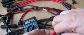
If no external damage is observed, you need to connect a multimeter. You need to check the resistance of the armor wire, so you need to switch the device to ohmmeter mode. After this, the armored wire is disconnected from the spark plug and ignition coil. The ends of the wire are connected to the contacts of the multimeter, after which the device will show the current resistance level.
Data on normal resistance values are applied to the insulating layer. For passenger cars, normal values are in the range of 4-10 kOhm. In this case, on one specific car, the data values for individual wires should not differ by more than 2.5-3 kOhm. If this threshold is exceeded, then there is a problem in the ignition system.
There are several ways to check the functionality of the wiring without using measuring instruments:
- Use of additional insulated wire. You need to strip both ends of the additional wire. Short one end to ground, and run the other bare end along the caps, joints and the entire contour of the wire being tested. If there is a defect, the tester wire will give a spark;
- You need to drive the car into an unlit box, open the hood, and start the engine. If there is a breakdown in the VP insulation, the damaged area will spark.
The easiest way is to take a working high-voltage wire and test it on each cylinder by elimination.
Replacement and connection of high-voltage wires on Kalina
This type of repair work is one of the simplest during car operation. Apart from a set of new wiring, the car owner will not need anything (it is better to buy silicone-based wires - they remain elastic at low temperatures). Before repairing the wiring, you need to “de-energize” the car by disconnecting the battery terminals. There is no need to start work if you are not confident in your own qualifications. It is better to pay experienced servicemen than to spend money on a new ignition system later.
The most important thing: do not disrupt the order of connecting high-voltage wires on Kalina . Each wire in the set is connected strictly to a specific cylinder. Wires usually vary in length. The sockets in the ignition unit also contain matching numbers.
The spark enters the cylinders in a certain order. The wires must be connected accordingly. The order is:
- First cylinder;
- Third cylinder;
- Fourth cylinder;
- Second cylinder.
It is better to check the location of the cylinders before starting work according to the vehicle’s operating manual. Cylinder numbers are read from left to right. The first one is closest to the timing belt.
It is recommended to remove and connect the wires one at a time to minimize the risk of incorrect connection order. During installation, you need to check that the new VPs do not rub against nearby structural elements, get pinched or break.
After completing the replacement, you need to “power” the car and start the engine. If the problems persist: the engine stalls or stalls, then the order in which the new wiring was connected was violated.
Replacing spark plugs Lada Kalina video instructions
Hi all. Today we will replace spark plugs on a second generation Lada Kalina with a sixteen valve engine.
I recommend buying Denso spark plugs. Inexpensive and go from replacement to replacement without problems. Order number: Q20PR-U11.
To replace spark plugs you will need:
- open-end wrench for ten
- seven-head wrench
- a long spark plug wrench because the wells are deep
Step by step replacement
1. First, disconnect the negative terminal of the battery. Ten key nut.
2. Remove the engine protective cover. We just pull it towards ourselves.
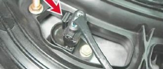
3. Using a socket head, unscrew the fastenings of the ignition coils. Each coil is secured with one bolt.
Ignition coil bolt locations.
4. Remove the power connectors from the coils. On the connector, press the latch with your thumb and pull it towards you.
5. Take out the coils. They fit tightly, so you need to apply some force.
We stack the coils so that we remember where each one was. During assembly you need to install it as it was.
6. Unscrew and change the spark plugs. I advise you to change one spark plug at a time. That is, they unscrewed one spark plug and screwed in a new one.
If you unscrew all the spark plugs at once, there is a chance that debris will get into the wells.
We tighten the candles without fanaticism.
7. Insert the coils all the way and tighten them with bolts.
8. Connect the connectors and battery terminal.
9. Put on the motor cover.
There are four grooves on the cover, and four matching holes on the motor. Just put the grooves into the holes and press.
10. Start the engine and enjoy the work done.
We also recommend:
Selected aspects of technical operation
Many inexperienced drivers, not understanding the essence of the breakdown, decide that an expensive replacement of the ignition switch or the wiring as a whole is necessary. Experienced drivers advise not to rush to conclusions. If, due to various circumstances, the ignition coil fails, the corresponding indicator lights up on the dashboard. The first thing the driver should do in such a situation is to drive the car into the garage and open the hood.
Often spark plugs fail due to a power surge or short circuit. As a result, the spark does not travel properly throughout the system. A number of other circumstances can cause a similar problem:
- the car was damaged in an accident;
- replacement of spark plugs may be required after lightning strikes the car;
- poor-quality previous repairs;
- use of non-original spare parts;
- failure to comply with technical inspection deadlines at the service center.
The ignition system can be damaged in any part of the circuit, so monitoring must be careful. It all starts with checking that the winding is properly connected to ground. It is necessary to carefully insert the contacts, focusing on the indicators of the device. Then one of the contact terminals of the device is connected to the central contact of the spark plug coil. In this case, the second contact is attached to ground.
If an infinity symbol is visible on the multimeter screen, this indicates that there is no short circuit in this area. This should tell the car owner that the ignition circuit is in perfect order. Car owners without sufficient experience in car maintenance should be guided by the following fact. If, in addition to the infinity icon, there remains a “1” on the monitor, which was there before connection, this indicates that the section is working properly.
Replacement of spark plugs may be required if there is an open ignition in the primary circuits of the module. The device is connected to the module contacts located at the edges. In this case, the stability of the indicators on the device screen indicates that there is a problem in the Kalina ignition switch
If the fault could not be detected here, then at the next stage the car owner should pay attention to the secondary winding of the module
Take a 16-cell ignition module. and rotates so that both wire ends are facing you. A diagnostic tool is connected to the terminals of the 4th and 1st cylinders. If the faults do not manifest themselves here, then it is necessary to check the 2nd and 3rd cylinders in the same way.
Self-diagnosis of the module
You can check the module in the following ways:
- Checking for weight. To carry out the test you will need a multimeter. The tester should be set to resistance measurement mode. One probe of the tester must be connected to pin 15, and the second one must be shorted to the housing. If the unit is working properly, the resistance should tend to infinity.
- Checking the primary windings of the short circuit. The primary windings are checked for breaks using a tester. To check, you need to connect the probes of the meter to the outer contacts on the short circuit. If the resistance tends to infinity, this indicates the presence of a break in one of the windings.
- Checking secondary windings. Since there are two windings, the test is carried out in two stages. First you need to check the short-circuit winding of cylinders 1 and 4. To do this, the multimeter probes must be placed in the appropriate terminals. A resistance of about 5.4 kOhm is considered normal. If the resistance tends to infinity, then there is a break in the winding. The short-circuit winding of cylinders 2 and 3 is checked in the same way.
In case of malfunction, the ignition module is replaced with a new one.
Rules for using the lock
- Position 0 is fixed. The ignition key can be removed from this position. In this position, external lighting devices can operate, including fog lights, illuminating the road ahead of the car. The hazard warning system works, you can use high and low beams, and turn on the audio system.
- Position 1 is fixed. The key cannot be removed from this position. The ignition is on. In this case, electrical power is supplied to all energy consumers of the vehicle, with the exception of the starter. Leaving the key in this position for a long time can drain the battery. Before turning on the starter, it is recommended to hold the key in this position for several seconds. During these seconds, the electric fuel pump will create the required pressure in the fuel system, which will greatly facilitate starting the engine, especially when it is cold.
- Position 2—turn on the starter. The key does not lock in this position. When released, it returns to position 1.
Do not hold the key in the starter position for more than 10 seconds. If the engine does not start, you need to take a break for 10-15 seconds and try again. Do not hold the key in this position while the engine is running. While Kalina’s car is moving, it is prohibited to remove the key from the lock. If you do this, steering failure will occur due to locking of the steering column and a sharp deterioration in the functioning of the braking system.
If during operation of the car the key remains in the lock, then when the driver's door is open, a continuous trill will be heard, signaling this. If the ignition is completely turned off and the key is removed from the hole, but the side lights are on, short beeps will be heard when the driver's door is open. The lock is capable of blocking the starter from turning on while the engine is running.
- directly from the ignition key;
- key for trunk and all door locks;
- remote control;
- immobilizer key APS-6.
- ignition;
- trunk and door lock key;
- APS-6 immobilizer learning key.
Mounting block fuse block VAZ tenth family
| without electronics | Search |
| -201212 | Search |
| required amount: 1 Voltage [V]: 12 | Search |
| required amount: 4 Voltage [V]: 12 | Search |
| Quantity: 1 Voltage [V]: 12 Number of connected contacts: | Search |
| Quantity: 1 secured with bolts/screws Number of mounting holes: 4 Number of Poles: | Search |
| SAE connector version Number of poles: 3 | Search |
| Voltage [V]: 12 Output voltage [V]: 27 | Search |
| without ignition cable Rated voltage [V]: 14 Output voltage [V]: 30 | Search |
| Search | |
| required amount: 4 Number of poles: 3 Voltage [V]: | Search |
| Mounting block (fuse block), also called a black box. If your car's electrical system suddenly stops working, then the first thing to do is check the fuses and relays. |
Fuse box diagram
- headlight high beam relay (K5);
- low beam headlight relay (K4);
- relay for monitoring and checking the serviceability of lamps (K1);
- tweezers for removing fuses;
- door power window relay;
- relay for turning on direction indicators and hazard warning lights (K3);
- starter relay;
- spare fuses;
- installation location of the fog lamp relay;
- relay for switching on windshield wipers and windshield washers (K2);
- rear window heating relay (K7);
- additional relay (K6);
- top row of fuses (F1-F10 are installed in numerical order from left to right);
- bottom row of fuses (F11-F20 are installed in numerical order from left to right)
- F1 5A License plate lighting lamps Instrument lighting lamps Side light warning lamp Trunk lighting lamp Left side side light lamps
- F2 7.5A Left headlight (low beam)
- F3 10A Left headlight (high beam)
- F4 10A Right fog lamp
- F5 30A Electric door window drive
- F6 15A Portable lamp socket Cigarette lighter
- F7 20A Electric cooling fan Sound signal
- F8 20A Rear window heating element. Relay (contacts) for turning on the heated rear window
- F9 20A Cleaners and washers for windshield, rear glass and headlights. Relay (coil) for turning on the heated rear window.
- F10 20A Reserve
- F11 5A Left side marker lamps
- F12 7.5A Right headlight (low beam)
- F13 10A Right headlight (high beam)
- F14 10A Left fog lamp
- F15 20A Electric seat heating Trunk lock lock
- F16 10A Relay-breaker for direction indicators and hazard warning lights (in hazard warning mode) Hazard warning lamp
- F17 7.5A Interior lighting lamp. Individual backlight lamp. Ignition switch illumination lamp.
- Brake light bulbs. Clock (or trip computer).
- F18 25A Glove box lighting lamp. Heating and ventilation control unit.
- F19 10A Door locking (central locking) Relay for monitoring the health of brake signal lamps and side lights Turn indicators with warning lamps Reversing lamps Generator excitation winding On-board control system display unit Instrument panel
- F20 7.5A Rear fog lamps
xn--2111-43da1a8c.xn--p1ai
Causes of malfunction
If translated literally, “Check Engine” is an engine error, which, according to the developers, should indicate to the driver that it is worth checking this particular system. So, there are several malfunctions associated with the activation of such an alarm. Let's look at the main problems that cause a "CHECK" in the engine.
Bad fuel
Low-quality gasoline, or as it is popularly called, “bad gas,” can cause the engine warning light to appear on the dashboard. So, troubleshooting can take a lot of time and labor. In order to get rid of the effect, you will have to clean the fuel system. To do this you need to do the following:
- Remove and clean the fuel tank.
- Remove the fuel rail and wash the injectors using a special stand.
- Replace the fuel filter, because as practice shows, after low-quality fuel it becomes clogged and completely loses its service life.
Spark plug
If one of the spark plugs is damaged, Check Engine appears on the dashboard. To fix the problem, you will have to dismantle all the elements and check them for resistance, as well as visually inspect their condition. Thus, if necessary, it is worth replacing the spark plug. As practice shows, it is best to install a completely new kit, which should be pre-adjusted, check the gaps, as well as the resistance. We have already talked about the choice of candles here.
Low fuel level
When the fuel level is low, the Check Engine sign appears on the instrument panel, which may also indicate that the fuel tank cap is not closed completely and the seal is broken.
Ignition coil
The absence of a spark in the cylinders immediately signals the electronic unit, which displays the inscription “check”. This may primarily be due to the fact that the ignition coil has failed. As a rule, it cannot be repaired and must be replaced.
Oxygen sensor
A clogged lambda probe is immediately visible from the inscription on the dashboard. Here, there can only be one way out - replacement. Of course, some car enthusiasts try to clean the oxygen sensor and are quite successful, but in practice it doesn’t last long and it quickly breaks down. Therefore, it is recommended to replace it immediately.
Catalyst
The catalyst may be another reason why the Check Engine message appears on the dashboard. Usually, this is due to the high mileage of the car, so when the car starts to take oil, you should prepare for the fact that this particular part will fail. But this is not the only reason. So, bad fuel or mechanical damage will lead to the replacement of this unit.
Wiring
Cases have been repeatedly noticed that when there are problems with the explosive wire, the message Check Engine pops up. Of course, the reason should be looked for in this system and, if necessary, it is worth replacing.
ECU
The electronic engine control unit can cause a “check” to appear. Thus, accumulated errors that have not been reset for a long time may cause the dashboard to display Check Engine.
This can be treated quite simply by resetting all accumulated errors. But, as experience shows, things can get to the point where you have to change the software and flash the ECU.
The mass air flow sensor repeatedly causes the Check Engine to appear on the dashboard. In order to determine serviceability, diagnostics should be carried out. If necessary, replace this unit.
BB: professional replacement
Replacing spark plugs for VAZ 2114 8 valves. how often do you need to change spark plugs on a vaz
If you have decided to contact the service for the process of replacing high-voltage wiring, then it is, of course, a good thing, but not worth the money that will be asked of you. They can also confuse your brain on the topic of how often high-voltage wires need to be changed, with the logic that it is better to take care of prevention in advance than to get stuck on the highway.
You won’t get stuck on the highway, the contact is not a sensor, even the last one doesn’t die right away. Replacement will cost from 1000 rubles. The advantage of service in this case will be the fact that they will look at the candles for you. And they will definitely be cleaned (they tend to become oily, which negatively affects the throughput for pulses through high-voltage wires).
Replacing high-voltage ignition wires is a simple operation accessible to every car enthusiast.
High voltage wires are designed to transmit the impulse from the ignition module or coil to the spark plugs. If the high-voltage ignition wires malfunction, interruptions in engine operation occur; it may vibrate and “triple” at idle.
Main malfunctions of high-voltage wires:
- insulation breakdown, current leakage
- core rupture
- increase resistance
- mechanical grinding of insulation
- unreliable attachment to the spark plug or ignition module
To replace high-voltage wires, you need to buy a new kit. When purchasing, it is better to choose silicone wires; they better retain elasticity and flexibility, especially in winter.
Before replacing, make sure that the ignition is turned off.
Don't remove all the wires at once
It is important not to disturb, since the spark must enter the cylinders in a certain sequence. For example, VAZ engines have cylinders operating in the order 1-3-4-2
That is, the spark is supplied first to the first cylinder, then to the third, then to the fourth and second.
Cylinder numbers are usually counted from left to right, with the first cylinder being the one closest to the timing belt.
The sockets on the ignition module are also numbered, but usually this module is located in places where it is simply not visible or is splashed with dirt.
Therefore, it is better to remove the wires one at a time. For example, remove the tip of the wire from the spark plug of the 4th cylinder and pull out the second end from the ignition module socket. Replace the removed wire with a high-voltage wire from a new set.
Usually the wires for each cylinder differ in length, so it is better to compare the removed wire with a new set and select one of a similar length from it.
We perform similar actions with the remaining wires.
When laying new wires, make sure that they do not touch moving parts anywhere or rub against adjacent elements.
After replacing the high-voltage wires, start the engine. If it “troubles” or stalls, it means you have violated the order of connecting high-voltage wires, which was mentioned above.
Ignition switch and features of its replacement
The ZZ is secured with one screw and is located on the steering column on the right under the steering wheel. Its design includes a locking device and a contact group. They are interconnected, working synchronously, and are activated using the ignition key.
When diagnosing faults in the electrical circuit, it is necessary to check whether the contacts close correctly when the position of the key changes. If any irregularities in the operation of the ignition protection are detected, it should be replaced (the author of the video is Renault Repair).
The procedure for replacing the ZZ on the Lada Largus consists of the following steps:
- Before work, disconnect the negative terminal from the battery to turn off the power supply to the car.
- Next, remove the steering column casing.
- At the next stage, by releasing the latch, we disconnect the connector with the wires of the contact group.
- Then, inserting the key into the ignition switch and setting it to the first position, remove the 33 wires from the dashboard.
- Next, unscrew the bolt that secures the ZZ.
- Use a screwdriver to press out the latches and remove the 3Z from the housing.
- We dismantle the faulty unit.
- Having installed a new spare part, we assemble it in the reverse order.
How to remove the ignition with your own hands?
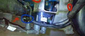
It is better to check the functionality with the device removed. On an 8-cl engine, the ignition module is located in the front of the car.
Location of module 8 cells
On an engine with 16 cells there are 4 modules and they are located in a different place.
The device removal procedure consists of the following steps:
- First of all, you need to de-energize the car by removing the negative terminal from the battery.
- If the engine has protection, it must be removed.
- Next, press the latch and disconnect the wire block from the unit.
- Then we disconnect the four high-voltage wires and put them aside so that they do not interfere.
- Next, using a key set to “13” you need to unscrew the fastenings of the module to the motor.
- Use a hex screwdriver to unscrew the mounting bolts and remove the device from the engine.
Depending on the tester’s performance, the issue of replacing the device or repairing it is decided. Before installing the module in its original location, its mounts and the engine housing mounts should be cleaned, which will improve the transmitted voltage across the ground. After installation, it is necessary to check the functionality of the engine ignition system.
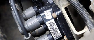
In order not to make a mistake when connecting high-voltage wires, you need to check the numbers on the block with the numbers on the wires; they must match. You should buy a new module with the same markings that were on the old one. To do this, you need to remember it when removing it. Then there will be no problems when installing a new device.
Location of the marking
Possible causes of ignition module malfunction
Despite the high reliability and durability of the ignition module, during operation it can fail, like any other mechanism. Among all possible causes of breakdowns, in 9 out of 10 cases the following occur and are diagnosed:
- Use of inappropriate components in the ignition system. High-voltage wires are selected based on the parameters of the module, since excessively high or low voltage creates malfunctions or burns out contacts.
- Defective or damaged parts, poor quality assembly. Defective components break down faster and damage other components or elements of the system. Practice shows that the selection of high-quality components and their periodic diagnostics allow the module to remain operational for a long time.
Replacing the ignition coil for Lada Kalina hatchback VAZ Kalina
Replacing the ignition coil on a Lada Kalina with an 8-valve engine yourself will take you no more than half an hour, without contacting a car service center or other workshops. To perform this work you will need a minimum of tools, namely:
- Hexagon 5 with a wrench or ratchet - the best option
- Or a regular L-shaped hexagon for 5
- 10mm wrench to disconnect the terminal from the battery
Procedure for removing and installing the ignition module
The first thing you need to do is open the hood of the car and disconnect the negative terminal from the battery; for this you will just need a 10 key, as was written above.
- We move the winding to the side, you can hook it to the cooling fan, then it definitely won’t interfere.
- Now we need a 5-point hex to unscrew the 4 bolts securing the ignition module housing, three of which are in plain sight, but the fourth is under the module at the bottom.
When all 4 bolts are unscrewed, you can safely remove the ignition module and install a new one in its place, if necessary
Please note that high-voltage wires must be connected in strict accordance so that the numbers on the block match the numbers on the wires
Transcript
1 Change of design Introduction of structural improvements and improvements (Growth of the operational performance) Electrical circuit 7540K PE3 basic 7540R E3 7540R DPS 7540K PE3 7540K E3 7540K PE3 7540K E PE E3 7540K PE3 7540K E PE E3 7540 K PE3 7540K E3 7540K PE3 7540K E3 7540K DPS 7540K PE3 7540K E3 7540K PE3 7540K E PE E3 7540K PE3 7540K E3 7540K BelAZ
3 Mounting of electrical equipment on chassis 7540K K (Mounting of electrical equipment on chassis) Headlight wiring harness 7540K K P V (Wire harness of headlights) Wire harness along spar 7540N K P V (Wire harness along spar) 7540K K P V Wiring harness by engine 7540K K P V (Wire harness at the engine) 7540K K P V Wire (Wire) K P V 7540K P V Wire harness of engine compartment lamp P (Wire harness of engine compartment lamp) Jumper N N Wire harness ( Wire harness) 7540K P Signal processing unit BOS-26 1 P (Unit of signals processing) SECI Terminator (Terminator) SECI N Installation of instruments on the panel 7540K K (Mounting instrumentations 7540K K on panel) Switch (Switch) 6FH P Switch (Switch) 6FH P Switch (Switch) 6FH P Switch (Switch) 6FH P Switch (Switch) 6FH P Switch (Switch) 6FH P Electronic instrument panel EPP-22 1 P (Electron instrumentation panel) Instrument panel PP-17 1 P (Instrumentation panel) SECI Cigarette lighter EZ N Switch PC-1 1 PC P 3
4 Switch Switch Switch Switch Switch Switch Switch 7555G Switch R Frame of switch ) Switch P Pilot lamp Pilot lamp Pilot lamp Pilot lamp 7555G Switch VK416M-01 1 P Pilot lamp Pilot lamp Pilot lamp
6 Display Power Viev Panel CICS Lamp holder LV Holder 5PM Lamp A Installation of headlights and sidelights 7540K K (Mounting of headlights and sidelights Hornless sound signal S AF P (Sound signal ) Hornless sound signal S AF P (Sound signal) Installation of taillights 7540A K and tail lantern (Mounting of taillights and tail lantern) Hornless sound signal S314G 1 P (Sound signal) Reverse motion horn P (Reverse motion horn) Installation of battery 7540K batteries and mounting wires 7540K (Mounting of storage batteries 7540K and mounting Wire) Positive jumper N (Jumper “+„) Wire (Wire) N Wire (Wire) N Wire (Wire) N Negative jumper N (Jumper “-”) Wire ( Wire) N Power relay PR P monostable (Mono-stable power relay) 6
BB: what do they look like?
Naturally, the technical conditions for the existence of working wires are the conditions of a permanent conductor. If we add here temperature changes and the imperfection of our world, we get the fact that the contact system fails within a certain period of time. And it comes with a frequency of 30,000 km.
This is a control figure that tells you when to change high-voltage wires. The fact is that over time, internal resistance begins to increase in them, preventing the impulse from passing as it should. In this case, you may notice the following behavior of the fourteenth:
- You want to press your sneakers to the floor, but the engine doesn’t respond
- The engine may simply stall
- At idle the engine troits
- It often happens that car owners themselves do not notice how high-voltage wires are pierced
Of course, this is not an indicator of a malfunction only in high-voltage equipment, but there is a high probability that it was they who flew. Surely, it is worth carrying out a test procedure for all contacts.
And the tester showed that the wires had a long life. Well, the high-voltage wires on the VAZ 2114 need to be replaced. The procedure, in principle, is not troublesome. If you were able to test them, then you can replace them. The main thing is to understand the order of connecting high-voltage wires.
The fourteenth is an improved version of the nine, it has higher ignition power. Therefore, contacts have been added to the four high-voltage wires for connection to the ignition terminal itself, through which a signal goes to the spark plugs; Also, in the fourteenth system there are contacts leading to the switch, as well as contacts for connecting the adsorber valve to the gasoline injection system control unit.
The connection diagram for high-voltage wires is quite simple:
- Cylinder 1 clings to the lower left contact
- Cylinder 2 clings to the upper left contact
- Cylinder 3 clings to the upper right contact
- Cylinder 4 clings to the lower right contact
This is sometimes called module bay interface in schematics. Essentially, everything is correct. The main thing is to understand that all cylinders are counted from left to right, like any count adopted from the logic of writing from left to right: 1,2,3,4. And the connection is obtained according to the following scheme: 1,3,4,2. Many people sketch and write down how the contacts were before removal. But, if you look at the module itself, there are docking numbers there. It's impossible to make a mistake.
Repair
Ignition module VAZ 2107
The module is dismantled and opened for repair purposes. For this you will need:
- Socket wrenches with heads 1, 13 and 17.
- Hexagon 5.
- Screwdriver.
- Soldering iron.
- Flux for aluminum.
- Stranded wire.
- Nail polish.
Opening the ignition module
Repair of the ignition module is carried out in the following order:
- On the removed device, open the case by prying it off with a screwdriver.
- Remove the silicone film covering the board.
- All aluminum is removed from the explosive contacts.
- On the board, new wires are soldered in place of all the dismantled old ones. To do this, the surface of the collector is cleaned of deposits, after which the board is heated to 180 o C (a characteristic smell will indicate when the desired temperature has been reached). During the soldering process, the ends of the wires are connected to the module.
- At the end of the operation, all contacts, the board and the module are covered with nail polish.
- The device is assembled in the reverse order, installed on the car and the engine is started. In case of normal operation, the ignition module is sealed tightly with sealant, while the wires are tucked inside the cavity so that they are not pinched at the edges by the plate.
If the device does not work, then a breakdown inside the module should be looked for more carefully. The transistor, electronic component may have failed, or there may be a break in the coil. Such a repair makes sense only if its price is significantly lower than the cost of a new part.
Misfire video
The ignition coil in the 8-valve version of the Lada Kalina power unit, as in the 16-valve version, plays a primary role. It allows the engine to start easily even in very unfavorable climatic conditions
This circumstance encourages owners to pay increased attention to this product. Even a minor deviation in the functioning of the coil can immobilize the car for a long time.
To minimize the risks of such a situation, we urge owners to follow the manufacturer’s regulatory recommendations. If the owner neglects this aspect, he will provoke himself into replacing the coil, which is very expensive. And in general, the ignition system must be maintained and operated carefully.
Checking the secondary windings of the module:
- So, we take the ignition module of the Lada Kalina and turn it so that the conclusions of the high-voltage wires are facing us. Now we connect the device wires to the outputs of the 1st and 4th cylinders. And then we check the 2nd and 3rd cylinders in the same way.
All these testing procedures are best carried out with the module removed; this is much more convenient than doing everything directly under the hood of the car. Removing this part is quite simple, you only need a 5 hexagon and a couple of minutes of time.
The cause of misfires in the operation of the power unit may be not only damage to the high-voltage wires, but also to the ignition module. The article gives recommendations on how to check the ignition coil on a Lada Kalina car with an 8 and 16 valve engine.
Source
Ignition coil malfunction factors
When the first signs of a breakdown appear, inexperienced owners first of all suspect the ignition switch or high-voltage wires as the culprit. Owners of Lada Kalina with experience recommend a balanced approach to resolving the issue. How to check the fault? If the coil fails, the dashboard will remind you of this by means of an indicator light.
A voltage surge or a short circuit inside the unit can cause damage to the spark plugs. In this case, the spark will not be able to generate correctly between the electrodes.
Device failure can also be caused by the following factors:
- the car getting into an accident, as a result of which you can observe the destruction of some components of the ignition unit;
- the car was struck by lightning;
- the previously completed repairs turned out to be of poor quality;
- use by the owner of non-original components in the designated system;
- ignoring maintenance intervals.
Regardless of the reasons, the owner of the Lada Kalina should diagnose the ignition system in detail. Sometimes a problem can be generated by the influence of several negative factors at the same time. This situation warns an inexperienced driver to tend to independently search for and eliminate breakdowns, because there is a likely risk of forced failure of other known-good components.
Let's sum it up
If the results of the diagnostic actions of the LADA Kalina car reveal that the ignition coil is faulty, then replacing this unit is a very simple undertaking. To implement the process, you will need a hex wrench. Before dismantling, we recommend that you remember the location of the high-voltage cables at the corresponding coil terminals. This will eliminate switching errors when installing the device.
The car jerks, there is no traction, vibration is felt, or the engine is rough; all these are symptoms of improper operation of the individual ignition coil (IIC). Other signs of a faulty ignition coil are the presence of errors 0301, 0302, 0303 and 0304, indicating misfire in one of the cylinders. Let's look at a few simple ways to check the ignition coil with your own hands.
It is worth noting that the process of checking IKZ on modern Lada cars (XRAY, Vesta, Largus, Granta, Kalina and Priora) does not have significant differences. All actions are performed in the same way.
Ignition coil malfunction factors
When the first signs of a breakdown appear, inexperienced owners first of all suspect the ignition switch or high-voltage wires as the culprit. Owners of Lada Kalina with experience recommend a balanced approach to resolving the issue. How to check the fault? If the coil fails, the dashboard will remind you of this by means of an indicator light.
A voltage surge or a short circuit inside the unit can cause damage to the spark plugs. In this case, the spark will not be able to generate correctly between the electrodes.
Device failure can also be caused by the following factors:
- the car getting into an accident, as a result of which you can observe the destruction of some components of the ignition unit;
- the car was struck by lightning;
- the previously completed repairs turned out to be of poor quality;
- use by the owner of non-original components in the designated system;
- ignoring maintenance intervals.
Regardless of the reasons, the owner of the Lada Kalina should diagnose the ignition system in detail. Sometimes a problem can be generated by the influence of several negative factors at the same time. This situation warns an inexperienced driver to tend to independently search for and eliminate breakdowns, because there is a likely risk of forced failure of other known-good components.