Ignition module
We have already learned what the ignition module is and what are the signs of its malfunction (unstable idling, failures during acceleration, engine twinkling).
In this article we will talk about how to check the ignition module with your own hands.
From personal experience: on the Internet, while reading various forums on this topic, I came across a post that broken high-voltage wires do not affect the ignition module in any way. In fact, faulty BB wires can lead to the fact that a spark, in search of the shortest direction, can be sent to a nearby relay, which contributes to module burnout.
Let's move on directly to checking the ignition module. To correctly and accurately check the ignition module, you need a device such as an oscilloscope. But, as a rule, the average driver does not have anything like this, except for the usual warning light and tester, so our task is to use only these devices that are available to everyone.
IGNITION MODULE CHECKING TECHNOLOGY
In service centers and service stations, the ignition module is checked using a special device - an oscilloscope, but we offer you a simpler technology that gives similar results.
You can check the ignition module using a regular tester (12-volt light bulb) and a multimeter - a device for checking ignition coils, which can be bought at any auto store for 300-500 rubles.
Before proceeding with the device itself, it is necessary to check the fuse and the wiring by which the unit is connected to the spark plugs and the generator.
The fuse is checked as follows:
- Disconnect the power wire block;
- We install one terminal of the multimeter on contact “A”, the second - on engine ground.
If the fuse is working properly, the tester will show a voltage of 12 V. If the voltage is too high or low, the fuse must be replaced.
The easiest way to check the power supply of the unit is with a control unit - we connect its wiring to contacts “A” and “B” and start the fourteenth. When the starter is turned on, the light should light up, otherwise it is necessary to look for problems in the circuit of contacts “A”, there is probably a break in it.
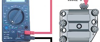
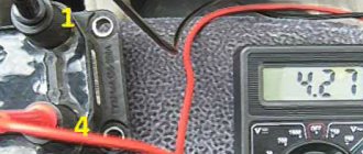
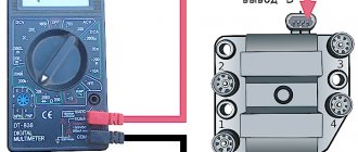
Checking the ignition module with a multimeter requires a device that can perform the functions of an ohmmeter. We put the tester in this operating mode and connect the terminals to the high-voltage wires going to the first and fourth cylinders, then we check the second and third in the same way. If the module is working properly, the tester will show a resistance of 5.2-5.5 ohms.
It is worth noting that only the first VAZ 2114 1.5L is equipped with the module, while modern fourteenth ones are produced with an ignition coil. Essentially, this is the same module, in the body of which there is no switch (it has been moved to the ECU), so checking the VAZ 2114 ignition coil is performed using a similar technology.
We check module 2114 using available methods
The most effective way to find out that the ignition module is not working is to take a device that is known to work and try to start the engine on it . It is clear that not every module from the second generation eights, nines and Samars may be suitable.
Depending on the type of ignition system, Samara may have a coil installed instead of a module, but we need exactly the module from the 8-valve injection 2114. Everything is simple here - the engine is running, which means the module has become obsolete, we replace it with a new one. However, there is a high probability that the high-voltage wires are broken and this will ruin not only the entire diagnostic picture, but also someone else’s ignition module.
Checking the integrity of high-voltage wires
Therefore, before checking the module itself, you need to make sure that the high-voltage wires are in order, do not break through to ground and allow current to pass through.
The action algorithm for subsequent verification is as follows:
- Checking the ignition module on the high-voltage circuit for an open circuit. To do this, you will need a multimeter that is set to resistance measurement mode. In the module, the ignition coils are connected in parallel - the first and fourth, second and third. To check, take the multimeter probes and install them (with the ignition off) into the connectors for high-voltage wires on the module. First 2 and 3, then 1 and 4 cylinders. The resistance between parallel coils should be 5.1-5.5 ohms. If the resistance is infinite, there is a break in the network and the module must be replaced.
Checking the ignition module for a break
- The last, traditional way to check any device is to knock, tug, move . No matter how ridiculous it may sound, sometimes after such a request the module comes to life. At least it’s enough to get to the nearest auto store and buy a new module, which costs between 2-2.2 thousand rubles.
Video about checking the ignition module on a VAZ-2114
Repair or replacement?
As the practice and experience of car repair technicians shows, most often it is not possible to repair this device. The module can only be replaced. If you follow the principle, it is possible to carry out repairs, but it will take a lot of time, effort and even money.
Installing the module
The best option is to purchase a new device. It costs around 2-4 thousand rubles. It all depends on the manufacturer and condition. You can buy a brand new one, although many people prefer used devices. Here the choice is yours.
Signs of breakdown
Disassembled
In fact, the symptoms of a malfunction in the VAZ 2114 ignition module are in many ways similar to the breakdown of other units. For example, you may observe the following phenomena:
- The engine is tripping;
- The car stalls at idle;
- There are problems when trying to start the car, etc.
That is, in fact, it may not be a module at all. Therefore, the only correct solution is to check the ignition module on your VAZ 2114.
PRINCIPLE OF OPERATION OF THE MODULES
The VAZ ignition module is an improved engine starting system. The principle of its operation is not very different from conventional systems. If in older systems the high-voltage voltage was generated by opening the contacts in the ignition distributor, then in the module the signals from the control unit serve as a pulse generator.
The control unit collects signals from sensors on the engine, generates a control pulse and sends it to the ignition module of the VAZ 2115. In it, a high-voltage voltage is generated from the on-board network voltage and sent to the cylinder spark plug to ignite the air-fuel mixture.
[custom_ads_shortcode1]
Functions of the VAZ-2114 ignition module
The ignition module in the VAZ-2114 solves important problems in the functioning of the car:
- first creates pulses passing through high voltage;
- then transfers them to the spark plugs.
The power supply of the unit involves operation starting from the on-board system of the vehicle, the minus wire is controlled by the body of the car. The subtlety of the module’s operation is that it simultaneously produces 2 sparks, one of which occurs at the moment of maximum compression of the air-fuel mass, and the other depends on the release, which is why it is called idle.
As for the connection method, the spark plugs are connected to the 1st and 4th cylinder, and the idle sparks fit to the 2nd and 3rd cylinder structure.
Video “Visual guide to replacing MH”
The STO TONN channel presented a visual aid for replacing the ignition module on a domestic VAZ 2114 car.
They brought a “wonderful” car to our service center, as the owner put it. And the miracle is that the owner declares: he changed EVERYTHING, the car worked on two cylinders and still works. We ask how they discovered that two cylinders were not working? The owner replies: I checked the spark, there is no spark on the second and third cylinders. I installed new wires, installed a new ignition module for testing, even installed new ECUs (brains), no spark in 2nd and 3rd and that’s it. The wiring says they checked it, everything is fine, there are no short circuits. Well, truly MIRACLES.
Here it is, our wonderful machine! VAZ 2114
Fig.1
Let's start in order. We connect diagnostic equipment and read errors, if of course there are any. We have several of them. We have installed the control unit January 7.2
Symptoms of a problem
It is extremely rare for two built-in coils to fail at once, so it is more likely to be possible to start the engine with a faulty unit. However, even an inexperienced driver will immediately suspect something is wrong. The malfunction will appear as follows:
- unstable (floating) idle speed;
- the engine has difficulty picking up speed;
- characteristic sound of the engine (triple);
- jerking when accelerating (while moving).
We recommend: How do additives work to reduce noise in a box?
Operating a car with such a breakdown is possible (you can drive to a garage or car service station), but it is not advisable unless absolutely necessary.
Similar signs of unstable engine operation are possible with a number of other ignition or fuel supply faults. To differentiate possible breakdowns, the performance of the ignition unit should be determined. It would be useful to check the contacts of the wires coming to the device, as well as their integrity.
Loss of dynamics
The VAZ 2114 model has never been distinguished by high dynamics, so even the slightest decrease in engine efficiency affects the use of the car. Loss of dynamics is a clear sign of improper operation of the ignition system or fuel supply system. When considering the signs of problems with the motor, one cannot fail to mention the loss of engine power as one of the key symptoms of its breakdown. If the module malfunctions, leaks in the paired cylinders are clearly observed, which manifests itself in low engine efficiency. It is clear that cylinder failure, even for a short period of time, does not allow the engine to operate at its full capacity. Operating a vehicle with reduced power is fraught with increased fuel consumption and uneven wear of the piston group.
Important ! If there is a sudden loss of power, you should stop driving the vehicle and begin repairs immediately.
The MZ cannot be quickly repaired, so if it malfunctions, a new unit should be installed on the machine. For reliability, you should “throw” a known working element of the ignition system into the car, and then check for changes in the operation of the unit.
Operating principle and location
The ignition module is controlled by a controller, which in turn receives information about the state of the vehicle from various sensors (IAC, mass flow sensor and others). The controller also sets the sequence of operation of the ignition coils or, in other words, regulates the supply of current to the spark plugs. The ignition module operates at temperatures from -40° to +130°.
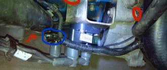
Finding its location is not difficult; high-voltage wires (HV) go from the module to the spark plugs; along them you can find the module.
Replacing the ignition module of a VAZ 2114
If repairing the MZ VAZ 2114 is impractical or impossible, then the problem with the operation of the device can be solved by replacing it.
The equipment needs to be changed only when the battery is disconnected. Otherwise, there is a risk of short circuits and failure of other electrical appliances.
How to remove the ignition module of a VAZ 2114?
The dismantling procedure is performed as follows:
- First, the on-board network is de-energized; to do this, loosen the negative clamp on the battery with a wrench.
- Then a search for MH is performed in the engine compartment. You can find the device by four high-voltage wires that go from the spark plugs directly to the equipment. These cables are disconnected from the MH.
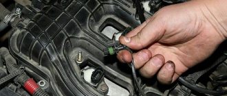
- Then the connector with conductors is disconnected from the device. It is necessary to disconnect the fixing fastener located on the ignition module housing.
- The MZ itself is secured to the bracket thanks to three nuts. You need to unscrew them using a key.
- After dismantling the fasteners, the device located on three studs is removed.
Connecting a new device
The equipment installation procedure is performed in reverse order; during installation, the following nuances must be taken into account:
- After installing the ignition module, you need to look at its surface. It is marked with numbers - 1, 2, 3 and 4. These symbols indicate the numbers of the cylinders to which the MZ should be connected.
- To properly connect the device, you need to look at the ends of the high-voltage cables. They are also marked with the same numbers. This is done in order to simplify the procedure for connecting the MH to the cables.
Connection diagram
The device must be connected in accordance with the diagram given in this section.
Connection diagram for MZ on VAZ 2114
How to check the device after connection?
Diagnostics of the operation of the new VAZ 2114 ignition module can only be performed using a special device - a high-voltage arrester.
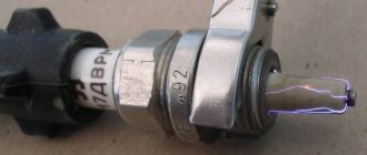
You can find it in almost any auto store. Using the equipment, you can diagnose the module, as well as high-voltage cables, for the presence of a spark. To check, you need to connect the device to the device and use its operating instructions.
Connecting and replacing VAZ short circuit
The procedure for removing and installing the ignition coil on old VAZ models:
- First, disconnect the central high-voltage wire leading to the distributor (ignition distributor).
- Disconnect all power wires from the coil contacts. Since they are fastened with nuts, you will need an 8 wrench for this.
- If you don’t know which wires to connect to which connector later, it’s better to immediately remember or mark them somehow, so that later during installation you can connect them correctly.
- Unscrew the coil housing. It is attached to a clamp (clamp), which is pressed to the car body with two nuts.
- After the work has been done, you can remove the ignition coil and replace it if necessary.
For new type VAZ cars:
- We remove the “minus terminal” from the battery.
- Remove the top protective cover of the engine. If the engine volume is 1.5 liters, then this part is missing and this step is skipped.
- We remove the high-voltage wires from the coil.
- Now, using a 13mm wrench, unscrew the two fasteners.
- Using a 17mm wrench, loosen one bolt securing the coil.
- We take out the module.
- Use a hexagon to unscrew the coil from the holder.
- Assembly is carried out in reverse order.
Particular attention should be paid to the connection, since high-voltage wires must be located in the strict order provided for by the design. If this is not done, the car will stall or the engine may not start at all.
Replacing the ignition coil on a VAZ is quite simple. Even a novice motorist can do this in his garage, and if everything seems too complicated, contact a car service center. Particular attention should be paid to the choice of product, since this will determine how well the engine and ignition system will work.
How to check the ignition module of a VAZ-2114 injector 8 valves: photo
When independently diagnosing an engine, its systems and characteristics, a minimum of equipment is used. For example, before checking the ignition module of an 8-valve VAZ-2114 car, it is advisable to have a special stand, the necessary software, or, in extreme cases, an oscilloscope. None of us have or will have such equipment, so for preliminary testing we will use available tools and devices.
How to check the ignition module of a VAZ-2114
Interruptions and jerking when driving, a shaking engine, difficult starting or even engine failure are the main signs of failure of the ignition module.
Ignition module
The difficulty of diagnosing on your own is that the module combines several devices at once, and it itself is made in a single housing, and there is no way to check each device separately. At least with your bare hands. Nevertheless, something can be done in order to, if not repair, then at least know for sure the cause of the malfunction.
Checking the quality of contacts
First of all, without dismantling anything, it is worth checking the quality of contact on all blocks of the low voltage circuit, and also establishing the presence of contact on the high voltage wires.
Checking the presence of power on the ignition module
Checking the voltage on the ignition module pads
In order to know that it is the module that is faulty, let’s check whether power is supplied to it. To do this, we find the connector in the block, and there we look for a contact marked with the letter A. To control the power supply to the module, take a multimeter, set it to measure alternating current up to 20 V, install one probe (negative) to engine ground and turn on the ignition. We install the second probe on terminal A on the block. If the electrical equipment is in good working order, the multimeter will show 12 V, which means that power is supplied to the module, we look further for the cause of the malfunction.
Checking the connector contacts
We have already carried out a preliminary check and made sure that power is supplied to the ignition module. Now it’s worth dealing with the contacts separately. With the ignition on, you need to connect a test lamp to contact A and contact B.
The control can be a regular low-power 12-volt lamp with soldered wires, or you can use a car test probe with a 12-volt voltage indicator.
Checking the ignition module
To check the functionality of the module, we attach the contacts from the test lamp or probe to terminals A and B, then crank the engine with the starter.
If the lamp begins to blink, the module produces a voltage break similar to a contact breaker.
In this case, everything is in order with contacts A and B.
If the lamp does not respond to the starter, the module is definitely faulty.
We check module 2114 using available methods
The most effective way to find out that the ignition module is not working is to take a device that is known to work and try to start the engine on it. It is clear that not every module from the second generation eights, nines and Samars may be suitable.
Depending on the type of ignition system, Samara may have a coil installed instead of a module, but we need exactly the module from the 8-valve injection 2114. Everything is simple here - the engine is running, which means the module has become obsolete, we replace it with a new one. However, there is a high probability that the high-voltage wires are broken and this will ruin not only the entire diagnostic picture, but also someone else’s ignition module.
Checking the integrity of high-voltage wires
We recommend: DIY car muffler repair without welding
Therefore, before checking the module itself, you need to make sure that the high-voltage wires are in order, do not break through to ground and allow current to pass through.
The action algorithm for subsequent verification is as follows:
- Checking the ignition module on the high-voltage circuit for an open circuit. To do this, you will need a multimeter that is set to resistance measurement mode. In the module, the ignition coils are connected in parallel - the first and fourth, second and third. To check, take the multimeter probes and install them (with the ignition off) into the connectors for high-voltage wires on the module. First 2 and 3, then 1 and 4 cylinders. The resistance between parallel coils should be 5.1-5.5 ohms. If the resistance is infinite, there is a break in the network and the module must be replaced.
Checking the ignition module for a break
- The last, traditional way to check any device is to knock, tug, move. No matter how ridiculous it may sound, sometimes after such a request the module comes to life. At least it’s enough to get to the nearest auto store and buy a new module, which costs between 2-2.2 thousand rubles.
VAZ models 8 and 16 valves
Despite the similarity in engine design, the ignition system of the 1.5-liter injection 16-valve engine differs from the 1.6 16-valve engine. The 1.6 liter engine uses an electronic contactless ignition system with individual coils on each spark plug. Therefore, there was no need for an ignition module. Such a system is more reliable and cheaper to operate, since if one coil fails, there is no need to replace the entire module.
The 16-valve 1.5-liter VAZ 2112 injection engine used the same non-contact ignition system as the 8-valve engine, but a different ignition module was installed. Its catalog number is 2112-3705010. The design of the module remains the same - two ignition coils (for cylinders 1-4 and 2-3) plus switch keys in a single block. The spark is supplied to the cylinders in pairs using the idle spark method. This means that sparking occurs in two cylinders simultaneously - in one on the compression stroke (working spark), in the second on the exhaust stroke (idle spark).
Checking the ignition module
Before checking the module itself, we need to check the block of wires coming to it.
- To do this, first of all, disconnect the wiring block, take the tester and connect one tester probe to the block at pin A, connect the other probe to engine ground.
- Turn on the ignition and look at the tester readings: the voltage should be around 12V. If there is no voltage, then you need to check the fuse going to the ignition module.
- The next step is to take a 12V test light and connect it to pins A and B.
- We turn on the starter and look: the lamp should blink, if it does not blink, then there is an open circuit on contact A.
- We perform this operation similarly with contact B.
There are several ways to check the ignition module, and we will look at some of them.
The first and easiest way to check a module is to replace the module with a known working one. Everything is simple here: we take the module from the donor’s car and change it. But there are certain disadvantages:
- The donor car may not be available, buying a new module does not suit our task;
- Not every car will have an ignition module: “of course!” - you say, - “from SAMAR this will do.” But not everything is so simple: as a rule, the first Samaras with a 1.5 liter engine are equipped with an ignition module. New Samaras with 1.5 and 1.6 liter engines are often equipped with ignition coils. Let me remind you that the ignition module consists of a switch and an ignition coil. In new Samaras, the switch is located in the ECU, so the module is eliminated as unnecessary, leaving only the coil. Take this fact into account and look for a new donor;
- It is imperative to make sure that the high-voltage wires are in good condition: how to check the high-voltage wires? Otherwise, there is a high probability that the ignition module will burn out.
The next method is the method of moving the module. To do this, we move the block of wires, knock and move the module itself. If, at the moment of our influence on the module, the operation of the engine changes noticeably, then the matter is most likely in poor contact. This malfunction is not catastrophic, so you can try to repair the module yourself: Repairing the ignition module. If the module cannot be repaired, it must be replaced (Replacing the ignition module).
To check we need a tester. Using a tester in ohmmeter mode, we measure the resistance at the paired high-voltage terminals of the ignition module 1 and 4 of the cylinder; and between cylinders 2 and 3. The resistance should be the same but vary around 5.4 kOhm.
Examination
It is a mistake to assume that damage to high-voltage wires does not in any way affect the condition of the module itself. Many people think of simply replacing high-voltage elements, but in reality they will still have to change the module.
This is explained by the fact that damaged or defective wires direct the wrong current, the configuration of which does not correspond to the necessary parameters. As a result, the spark hits inaccurately or ineffectively, causing the module to burn out and become unusable.
In general, the best option for checking the ignition module on a VAZ 2114 is to use an oscilloscope . But, firstly, not every driver has it, and secondly, few people can use them. Therefore, we will carry out the check using improvised means:
- 12-volt light bulb;
- Tester (available for little money at any auto parts store).
Let's start with preliminary manipulations with the accompanying elements of the ignition module.
- Check the wiring harness. It is disconnected and the voltage indicator is checked.
- To do this, fix the tester on contact A, and connect the other terminal to engine ground.
- In normal condition, the voltage reading will be 12V.
- If there is no voltage, most likely the fuse has blown.
- If everything is fine, transfer the terminals of your tester to contacts A and B, start the car. In this case, the starter should turn and the 12-volt light should blink.
- In the absence of these phenomena, we can talk about the presence of a break in circuit A of the contacts.
Next we go to the ignition module itself.
There are several ways to check the condition of your unit. Therefore, let's look at each of them.
- Set the tester to ohmmeter mode. Use it to measure the resistance on the high-voltage lines going to cylinders 1 and 4, and then, by analogy, to the wiring of cylinders 2 and 3. In normal condition, the device will give you readings from 5.2 to 5.5 ohms.
- Give the device a gentle tug. Thus, you will shake the wiring block and the module. Moreover, this must be done in the operating mode of the power unit. If the device works without obstruction when loosened, everything is fine, you are lucky. If not, you will again have to study the condition of the wiring.
Third way
The third method is considered the simplest, since it involves replacing your device with a similar one that works exactly. But to do this, you have to find a full-fledged twin. We are talking about an ignition module from a car similar to yours in terms of year of manufacture and power unit used. It’s just that 1.5-liter engines have modules, and 1.6-liter engines have coils.
But to replace a module with a module, you will have to first dismantle yours. This is done as follows:
- Remove the negative terminal from the battery, which will allow you to turn off the power to the car;
- Disconnect four high voltages from the ignition module;
- Disconnect the wire block. To do this, you need to release the special clamp that holds the block on the module;
- Next, unscrew the three nuts. With their help, the module is held on the bracket;
- There are three long pins on the bracket, from which the module can simply be pulled off.
Having dismantled your module, you can put another unit in its place, thereby verifying the functionality of that one and the malfunction of yours.
PURPOSE OF THE IGNITION MODULE VAZ 2114
The ignition module is a complex electronic device that performs the function of converting electricity coming from the generator into high voltage current (30 kW) and distributing it between the spark plugs.
Ignition module connection diagram
The unit produces a spark to two spark plugs, which are connected to the cylinders of the power unit, to spark plugs 1 and 4 of cylinders - an idle spark, to spark plugs 2 and 3 - a working one. The period of spark supply is calculated by the electronic on-board control of the fourteenth; it occurs when the engine stroke requires ignition of the fuel in the cylinder.
The device itself is connected to the BES (on-board electrical network) of the VAZ 2114; for normal operation, the module requires a constant power supply of 12 Volts.
The unit consists of 2 high-voltage transformers, each of which is connected to electronic control units and VP (high-voltage wires). The dimensions of the device are quite compact - 11 * 11.7 * 7 centimeters, it weighs 1.32 kilograms.
The cost of the device varies from 1500 to 3000 rubles. In the lowest price category, there are products from Chinese OEM manufacturers whose service life is unpredictable - they can either work for several hundred thousand kilometers without any breakdowns, or begin to act up just a few months after purchase.
Reviews from the owners of the fourteenth show that the most reliable and durable devices are from Bosch. A good option is BoschM7.9.7, which is also suitable for the VAZ 2115.
How to check the ignition module of a VAZ-2114
Interruptions and jerking when driving, a shaking engine, difficult starting or even engine failure are the main signs of failure of the ignition module.
Ignition module
The difficulty of diagnosing on your own is that the module combines several devices at once , and it itself is made in a single housing, and there is no way to check each device separately. At least with your bare hands. Nevertheless, something can be done in order to, if not repair, then at least know for sure the cause of the malfunction.
Checking the quality of contacts
First of all, without dismantling anything, it is worth checking the quality of contact on all blocks of the low voltage circuit , as well as establishing the presence of contact on the high voltage wires.
Checking the presence of power on the ignition module
Checking the voltage on the ignition module pads
In order to know that it is the module that is faulty, let’s check whether power is supplied to it. To do this, we find the connector in the block, and there we look for a contact marked with the letter A. To control the power supply to the module, take a multimeter, set it to measure alternating current up to 20 V , install one probe (negative) to engine ground and turn on the ignition. We install the second probe on terminal A on the block. If the electrical equipment is in good working order, the multimeter will show 12 V, which means that power is supplied to the module, we look further for the cause of the malfunction.
conclusions
As a rule, the ignition module is not restored and is simply replaced with a new one. There is no guarantee that he won't start bucking again. This will save a lot of gray brain cells and save a lot of personal time, which can be spent on something more necessary. It's better to buy a new one and not worry.
However, as children, we all loved to take toys apart to find out what was inside and how everything worked. It’s not a pity to try to disassemble a broken unit, but still throw it away if nothing works. But if you repair it, you will get so much pleasure and pride in yourself!
Design
The design of the ignition module is quite complex, since it combines technology and electrics. The device serves to create high voltage transmitted to the spark plugs. It is this supplied current that is the basis for ignition.
The operation of the module ensures fuel combustion and, accordingly, engine operation. In very simple terms, the car won’t go anywhere without the module.
We recommend: All about the oil in the gearbox of a Gazelle car
For VAZ models, the use of two types of ignition modules is provided:
- Separate;
- Block.
Block ones differ in that the coils operate one per pair of spark plugs. These are the devices that are installed on the “fourteenth” model of the domestic automaker.
The coil distributes power to two candles at once, and its design includes the following elements:
- High voltage wires;
- Low voltage terminals;
- Secondary and primary winding;
- Core.
Separate modules, where the coils supply a separate circuit to each of the 4 sections, are distinguished by the output of high-voltage wires through a spring contact. Block ones are easier to check, they are easy to remove and return to their place.
It is noteworthy that with a size of 11x11x7 centimeters, this block weighs about 1.5 kilograms.
Symptoms of a faulty ignition coil
The module's task is to transmit voltage to the spark plugs through high-voltage conductors. In this case, the electronic control unit (ECU) controls the transmission process by sending charged pulses to the winding. As a result, a spark is formed necessary to ignite the fuel inside the combustion chamber.
If this circuit is broken, the engine will run intermittently, which will affect the safety of the car. There are several signs that make it clear to the car owner that the coil and the ignition system as a whole need to be checked:
- Insufficient engine power when accelerating the car;
- When you press the gas pedal, the car does not pick up speed, especially when overtaking;
- When the car is idling, the engine runs intermittently;
- The spark plug does not produce a spark.
Advice. When the first signs of a vehicle malfunction appear, the first thing you need to do is look at the spark plugs, then make sure the crankshaft position sensor is working, and only then move on to the module.
What does the ignition module consist of?
The ignition module built into the VAZ-2114 consists of 2 high-power transformers and the same 2 electronic-based control units. One side of the product has 4 outputs at once; they are responsible for connecting the candles. To keep the structural components in their original form and protect them, the manufacturer provides a plastic coating. The weight of the entire structure slightly exceeds 1 kg.
The spark plugs suitable for the engine are fixed together with the ignition module by running high-voltage wiring. A device called a “controller” controls the process. First, he takes the performance indicators of the structure, then analyzes them and, finally, decides what should be changed to achieve optimal performance - the crankshaft rotation speed, the temperature reached by the coolant in the VAZ-2114, or the engine load.
Possible causes of failure
The weak point of the ignition coils and modules is the secondary winding, which generates a high voltage pulse. A coil break or breakdown may occur in it. The following factors lead to this phenomenon:
- use of low-quality or unsuitable candles;
- operation with non-functioning high voltage wires;
- frequent attempts to check the spark.
The high-voltage pulse arising in the secondary winding must be realized (spent). If this does not happen (if the integrity of a high voltage wire is broken, for example), a high-energy electrical pulse seeks an outlet. He will find it, with a high degree of probability, in the thin secondary winding.
Often, a module malfunction occurs when the integrity of poor-quality factory soldering of wires going to the switch elements is violated. This happens from vibration. Also, the cause of non-working coils can be a banal contact failure in the incoming connector. Another factor leading to a malfunction of the ignition unit is often moisture that gets on the device during washing or driving in unusual conditions.
What should I do if the problem remains after replacing the module?
If, after performing the repair, problems in the operation of the MH remain, then there is a possibility that the cause of the problem was not in the module. It is necessary to diagnose the remaining elements of the ignition system.
Spark plugs and ignition system
Features of checking spark plugs and other components:
- Before dismantling the devices, it is necessary to disconnect the ends of the high-voltage cables. Their condition is checked for damage. Defects in the tips often lead to malfunctions in the spark plugs. If there is damage, the wires are replaced. It is also necessary to assess the condition of the “high-voltage workers” themselves. They are not allowed to have any defects or damage to the insulation.
- After disconnecting the tips, the spark plugs are dismantled and a special spark plug wrench is used to unscrew them.
- After dismantling, the condition of the devices is assessed. The color of the parts must be brown; carbon deposits and soot on the electrodes are not allowed. If there are uncharacteristic marks, the devices are cleaned using a metal brush or fine-grained sandpaper. For a better effect, the electrodes of the candles can be heated on the stove.
- The condition of the gap between the part and the electrode element is checked. If it is too large, this indicates that the device is not working correctly. The spark plugs will need to be replaced.
ABOUT THE POSSIBILITIES OF MODULE REPAIR
Most breakdowns of this device lead to its replacement, but sometimes it is possible to repair the ignition coil to return it to service. This is especially true in cases where moving or tapping changes the behavior of the motor. If you have the ability to use a soldering iron and a multimeter, you can try to get it back into operation.
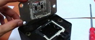
You need to remove the metal back cover, under which the electrical parts of the module are filled. You need to try to carefully get rid of the silicone and its “insides” will be revealed to your eyes. Find broken or “bad” contacts and solder them.
The conductors in the block are aluminum, so special solder is needed to solder them. After this, close the back cover and check its functionality. If the repair result is positive, you need to open it again and fill the inside with silicone.
If the result is negative, then the block must be replaced. True, owners with extensive amateur radio experience continue to “dig” further. You can try replacing the electronic switches. Basically, these two elements become the culprits of failures of the engine starting system.
[custom_ads_shortcode1]
How to remove and change the ignition module on a VAZ-2114: photo and video
The ignition module receives a control pulse from the control unit and transmits it to the cylinder plug to ignite the air-fuel mixture. The device itself consists of two coils that produce high voltage and a two-channel switch. The body of the product is made of durable plastic.
Ignition module failure
Malfunctions in the operation of this element may manifest themselves as follows:
- Noticeable decrease in engine power.
- No spark on one of the spark plugs.
- Noticeable "swimming" of the idle speed.
These signs indicate that there is a problem with the ignition module. If they appear, it is worth replacing the ignition module.
Replacing the ignition module on a VAZ-2114
Packaging from the original part
To replace the ignition module, you will need a rag and a key number 13. It is best to do it on some level ground.
Progress
- Open the hood and disconnect the battery terminals;
- Get the high-voltage wires coming from the ignition module to the spark plugs. At the same time, it is necessary to remember their location, because if the location of these wires is changed, the new spare part may immediately fail. You can make notes to be sure of the result.
- Carefully disconnect the connector with cables from the module. Then unscrew the nuts using a 13mm wrench and remove the block from the motor.
Location of the ignition module under the hood
- After this, you need to install a new module. A rag is needed to wipe the installation area of the module after removing it.
Checking the operation of the ignition module (video)
What should I do if the problem remains after replacing the module?
First of all, you need to check the operation of the new module.
Checking the ignition module
Resistance between contacts: 1 and 4, 2 and 3 - should not be higher than 5.8 kOhm!
If after replacing the ignition module nothing has changed, it means that other elements of the ignition system are faulty.
Spark plugs and ignition system
If this does not help, then you need to check the spark plugs and replace them if necessary (see selection of spark plugs for the VAZ-2114).
Inspecting the condition of the spark plugs
Before this, you need to remove the tips of the armor wires. To unscrew the spark plugs, you will have to use a special wrench. Then the candles need to be inspected: they should have a normal brown color and there should be no soot or soot on the surface.
If replacing the module did not correct the situation, and there is carbon deposits on the spark plugs. This means that the rings or pistons are worn out, they need to be replaced, and the spark plugs must be cleaned and put back into the socket. It is also worth checking the gap between the spark plugs and the electrodes - too large a distance has a bad effect on the operation of the devices.
CHANGING THE IGNITION SYSTEM MODULE
When repairing the ignition module does not produce positive results, all that remains is to look for and install a new device. Most mechanics recommend choosing a “GM” device as a very reliable product. Its cost varies in different regions, but is close to 2000 rubles.
Replacing the ignition module can be done independently, there are no special features, and no special devices are needed. For work, prepare:
- Ignition unit for replacement;
- Key to "13";
- Rags.
The work can easily be done in a garage or on level ground. Work order:
- Open the engine compartment hood and disconnect the battery terminals. It is quite enough to remove the terminal only from the negative side.
- After this, we remove the high-voltage wires from their installation locations. You need to remember where which wire was located. If you doubt your abilities, then make marks. Wires cannot be swapped. A new spare part can be damaged.
- At the next stage, carefully disconnect the connector with wires from the module. Use the key set to “13”, which unscrews the three nuts securing the device to the motor.
- When the nuts are removed, the device is removed from the engine.
Now they use rags to wipe the installation area and around it. Carefully inspect the new device and begin installing it. It is carried out in the reverse order to removal.
Once again I would like to remind you of the importance of installing high-voltage wires in their places. If difficulties still arise, then take another look at the block. It shows the numbers of high-voltage wires.
Numbers – the order of arrangement of explosive wires in the module.
It should be noted that on sale you can still find old-style ignition modules that do not have wire numbers marked on the high-voltage terminals. If you purchased just such a device, be careful when installing it.
- * Why clean the throttle...
- * Priora. The AirBag light is on...
- * Computer engine diagnostics…
- * Nissan March error P0100 is on...
- * Mercedes C200 error P0171 is on, smell of gasoline...
- * Engine troubles, speed fluctuates, P0300 Gazelle...
- * The electric power steering (EUR) of the viburnum turns off, error C1044 is on...
- * Buggy firmware (programs) VAZ, GAZ, UAZ...
- * Volkswagen polo, error 00268 is on for valve N93, automatic transmission twitches...
- * Engine chip tuning, increasing engine power. Reviews, comments...
- * Battery case (charging case) for iPhone, Samsung. Review, tests, reviews….
- * Increased fuel consumption of the VAZ 2110, flooding the spark plugs....
- * Gazelle does not gain momentum, error P2138 is on....
- * VAZ 2114 is malfunctioning, the cylinders are not working, the ECU is burned out....
- * Ford Focus 2 does not respond to the gas pedal, burner error P2176....
- * Portable external battery for phone, tablet….
- * Installing a new instrument cluster 385.3801-10 on a Gazelle….
- * Toyota Camry stalls, the speed drops, it is difficult to start, the “CHECK” lamp is on....
DocumentationDocumentation DiagramsConnection diagram for the ignition switch on the VAZ-2113, 2114 and 2115Pinout of the ignition switch for the VAZ-2113, 2114, 2115:
- comes +12V for the microphone of the sensor of the inserted key;
- the mass comes when the driver's door is open;
- +12V goes to the starter (pin 50);
- +12V goes out after turning on the ignition (pin 15);
- +12V goes out when the key is inserted to pin 5 of the BSK;
- comes +12V to illuminate the lock cylinder;
- +12V comes from the battery (pin 30);
- not used.
| Photo 1, pinout of the ignition switch of a VAZ 2114 | Photo 2, pinout of the ignition switch of the VAZ 2114 |
Date added: 07/14/2014 Author: Dmitriev Alexander
| None © AutoService | Online store, Ekaterinburg Unified information service: |
- * Why clean the throttle...
- * Priora. The AirBag light is on...
- * Computer engine diagnostics…
- * Nissan March error P0100 is on...
- * Mercedes C200 error P0171 is on, smell of gasoline...
- * Engine troubles, speed fluctuates, P0300 Gazelle...
- * The electric power steering (EUR) of the viburnum turns off, error C1044 is on...
- * Buggy firmware (programs) VAZ, GAZ, UAZ...
- * Volkswagen polo, error 00268 is on for valve N93, automatic transmission twitches...
- * Engine chip tuning, increasing engine power. Reviews, comments...
- * Battery case (charging case) for iPhone, Samsung. Review, tests, reviews….
- * Increased fuel consumption of the VAZ 2110, flooding the spark plugs....
- * Gazelle does not gain momentum, error P2138 is on....
- * VAZ 2114 is malfunctioning, the cylinders are not working, the ECU is burned out....
- * Ford Focus 2 does not respond to the gas pedal, burner error P2176....
- * Portable external battery for phone, tablet….
- * Installing a new instrument cluster 385.3801-10 on a Gazelle….
- * Toyota Camry stalls, the speed drops, it is difficult to start, the “CHECK” lamp is on....
DocumentationDocumentation Diagrams Diagram of the engine control system (ECM) VAZ-2110, 2111 and 2112
- – controller;
- – block of the ignition system harness to the ABS cabin group harness;
- – diagnostic block;
- – immobilizer warning sensor (APS);
- – immobilizer control unit (APS);
- - ignition coil;
- - spark plug;
- – nozzles;
- – electric fuel pump;
- – block of the ignition system harness to the electric fuel pump harness;
- – block of the fuel level sensor harness to the ignition system harness;
- – block of the ignition system harness to the injector harness;
- – block of the injector harness to the ignition system harness;
- - speed sensor;
- – idle speed regulator;
- – throttle position sensor;
- – coolant temperature sensor;
- – mass air flow sensor;
- – camshaft position sensor (phases);
- – oxygen sensor;
- – crankshaft position sensor;
- - knock sensor;
- – solenoid valve for purge the adsorber;
- – block of the ignition system harness to the instrument panel harness;
- – controller power supply fuse;
- – ignition relay;
- – ignition relay fuse;
- – fuse for the power supply circuit of the electric fuel pump;
- – electric fuel pump relay;
- – electric fan relay;
- – block of the ignition system harness to the air conditioner harness;
- – pads of the ignition system harness to the front harness;
- – electric fan of the cooling system;
- – block of the instrument panel harness to the ignition system harness;
- – ignition switch;
- – instrument cluster;
- – on-board control system unit;
- - starter relay;
- – mounting block;
A – to the “plus” terminal of the battery; B1, B2 – grounding points of the ignition system harness;
2115-3724026-11 – Ignition system harness;
- – block of the ignition coil wiring harness to the ignition system harness;
- – block of the ignition system harness to the ignition coil wiring harness;
- – ignition coils;
- – immobilizer warning sensor;
- – immobilizer control unit;
- - spark plug;
- – nozzles;
- – diagnostic block;
- – block of the ignition system harness to the ABS cabin group harness;
- – controller;
- – electric fuel pump;
- – block of the ignition system harness to the fuel level sensor harness;
- – block of the fuel level sensor harness to the ignition system harness;
- – block of the ignition system harness to the injector harness;
- – block of the injector harness to the ignition system harness;
- – block of the ignition system harness to the side door harness;
- - speed sensor;
- – idle speed regulator;
- – throttle position sensor;
- – coolant temperature sensor;
- – mass air flow sensor;
- – oil pressure warning lamp sensor;
- – camshaft position sensor (phases);
- – oxygen sensor;
- – crankshaft position sensor;
- - knock sensor;
- – solenoid valve for purge the adsorber;
- – coolant temperature indicator sensor;
- – block of the ignition system harness to the instrument panel harness;
- – block of the instrument panel harness to the ignition system harness;
- – ignition relay;
- – ignition relay fuse;
- – fuse for the power supply circuit of the electric fuel pump;
- – electric fuel pump relay;
- – electric fan relay;
- – controller power supply fuse;
- – block of the ignition system harness to the air conditioner connector;
- – instrument cluster;
- – ignition switch;
- – electric fan of the cooling system;
- – on-board control system unit;
- – additional starter relay;
- – contacts of the 8-terminal blocks of the instrument panel harness and the front harness;
- – contacts of the 21-terminal blocks of the instrument panel harness and the rear harness;
- - trip computer;
- – diagnostic connector;
A, E – to the “plus” terminal of the battery; B1 – grounding point of the ignition coil wiring harness; B2 – grounding point of the fuel level sensor harness; B3, B4 – grounding points of the ignition system harness; C – to the starter; D – to the driver’s door interior lamp switch;
Diagram of the engine control system (ECM) Euro-3 Bosch 7.9.7+, M73 VAZ-2113, 2114 and 2115 (2111-1411020-30). Engine 1.6 liter 8 valve.
1 – controller; 2 – block of the ignition system harness to the ABS cabin group harness; 3 – diagnostic block; 4 – immobilizer warning sensor (APS); 5 – immobilizer control unit (APS); 6 – ignition coil; 7 – spark plugs; 8 – nozzles; 9 – electric fuel pump; 10 – block of the ignition system harness to the fuel level sensor harness; 11 – block of the fuel level sensor harness to the ignition system harness; 12 – block of the ignition system harness to the injector harness; 13 – injector harness block to the ignition system harness; 14 – speed sensor; 15 – idle speed regulator; 16 – throttle position sensor; 17 – coolant temperature sensor; 18 – mass air flow sensor; 19 – camshaft position sensor (phases); 20 – control oxygen sensor; 21 – crankshaft position sensor; 22 – knock sensor; 23 – solenoid valve for purge of the adsorber; 24 – rough road sensor; 25 – diagnostic oxygen sensor; 26 – block of the ignition system harness to the instrument panel harness; 27 – controller power supply fuse; 28 – ignition relay; 29 – ignition relay fuse; 30 – fuse for the electric fuel pump power supply circuit; 31 – electric fuel pump relay; 32 – electric fan relay; 33 – block of the ignition system harness to the air conditioner harness; 34 – pads of the ignition system harness to the front harness; 35 – electric fan of the cooling system; 36 – instrument panel harness connector to the ignition system harness; 37 – ignition switch; 38 – instrument cluster; 39 – on-board control system unit; 40 – starter relay; 41 – mounting block; A – to the “plus” terminal of the battery; B1 – grounding point of the fuel level sensor harness; B2, B3 – grounding points of the ignition system harness;


