The engine cooling system is liquid, closed type, with forced circulation of liquid.
The exhaust system is a set of muffler elements connected to the exhaust manifold. It is possible to install an exhaust gas catalyst into the gap between the exhaust pipe and the resonator.
Single-disc, dry, with a diaphragm-type central spring.
Front suspension - independent, wishbone, spring, with hydraulic telescopic shock absorbers and anti-roll bar Rear suspension - wishbone, spring, with hydraulic telescopic shock absorbers
The front brakes are ventilated discs. The rear brakes are drum brakes.
BODY
4-door, sedan (5 seats)
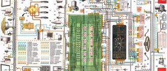
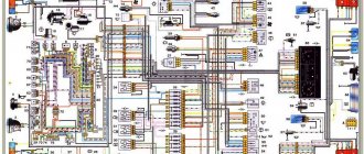
Every modern car today is equipped with an electrical part. The electrical diagram of the VAZ 21214 Niva injector allows, if necessary, to find all the elements included in the on-board network, which is especially important when faults occur in the wiring. Everything a driver needs to know about electrics in domestic SUVs is described in this article.
Niva index designations
Differences in generators
Wiring differences
Photo gallery "Electrical systems of SUVs"
Video “Laying wiring in the sports version of the Niva”
Comments and Reviews
Niva index designations
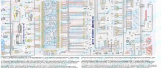
Detailed electrical diagram of Niva
The wiring diagram may vary slightly depending on the design features of the vehicle.
First, let's look at the index notation:
At the beginning of the article there is a diagram of the VAZ electrical equipment using the example of the Niva 2121 model. If you are the owner of version 2131 or any other, then there will be a difference in the circuit diagram, but not fundamentally. If we are talking about carburetor engines, then in this case the battery charging circuit, as well as the ignition, will not be protected (video author - Nail Poroshin).
We carry out the adjustment ourselves
- The first step is to install the cylinder in the correct position. Installation is carried out so that the mark on the pulley is exactly at 0 degrees.
- Set how the slider is positioned. It should be aimed at the first pin in the cylinder.
- Use a strobe light and make sure the ignition is working properly.
- Make the electrical connections in the battery: minus to ground, plus to plus.
- The sensor must be connected to the high-voltage wire on the cylinder. The mark should connect to the crankshaft pulley.
- Start the engine at low speed (up to 800 rpm). Use a stroboscope to illuminate the pulley, and if the mark coincides with the middle mark, then the ignition is set correctly.
- Otherwise, the engine should be turned off and the meter should be loosened. In order to decrease the angle, turn the sensor clockwise; to increase it, turn it counterclockwise. Record and test the calibration again with the ignition on.
- Next, you should perform manipulations with the distribution sensor. Open the lid. Match the stator and rotor mark.
- Start the engine, bring the temperature to 75-80 degrees. When the speed is 50 km/h, sharply press the gas pedal.
- If the ignition was installed correctly, a short-term detonation will occur when you press the gas.
Also interesting: The battery indicator came on
Then there are two possible developments: early and late ignition. Let's consider solutions for both cases:
- In the case of late ignition, when there is no detonation, you should change the position of the sensor clockwise.
- In the case of early ignition, when detonation lasts longer than necessary, the sensor is rotated counterclockwise.
Niva 21213 can be subject to adjustment of the starting system by the gap at the edges of the valves, if the carburetor is removed, or by the crankshaft speed directly on the car. In the first case, the gap at the location of the lower edge (in the direction of air movement) from the throttle valve is set to a width of 1.1 mm.
It is adjusted with a screw that has a 0.7 cm hexagon on the head and a slot from the shank. This operation is carried out with the cam lever turned counterclockwise from the starting system control (all the way). In the same position, the gap at the lower edge of the air damper is set to 3 mm using a screw in the cover from the diaphragm mechanism in the starting system (you need to loosen the lock nut).
The principle of powering a carburetor engine Adjusting the Niva starting system directly in the car saves time: You need to remove the air filter from the engine, pull the control lever towards you from the air damper, and start the engine. When the air damper is forced to open (by touching a flat screwdriver to a third of its full angle of rotation) using a screw (next to the lever on the axis from the throttle valve from the first chamber), the initial rotation speed is set to 2.08.mar.0 thousand.
If you have a gas analyzer, then the carburetor adjustment in the starting system part can be done based on the amount of CO (carbon monoxide) in the exhaust gases. If, with the choke control lever fully extended, the gas rate is 8%, then everything is in order. If there is less gas than this value, then the screw on the cover of the diaphragm mechanism is tightened; if there is more, it is unscrewed and repeated measurements are taken.
It is necessary to adjust the idle speed of the Niva 2121 so that there is less carbon monoxide in the exhaust gases and so that the engine runs stably. At service stations, such work is carried out with gas analyzers on the MV. In the garage, adjustments can be made using the tachometer.
Features of electrical equipment
The electrical circuit of the VAZ model 21213 has certain differences with the model 2121, in particular:
It should be noted that differences in the Niva circuit may lie both in the generator units and in the electrics themselves.
Differences in generators
In any case, the differences in the wiring diagram of the models will primarily depend on the power unit - carburetor or injection.
The main differences in carburetors:
And although these generators are different, they have certain similarities in design. In any case, it is a synchronous AC device. In addition, these units have a built-in rectifier and output voltage regulation mechanism.
Wiring differences
If we talk directly about wiring, then depending on the car model, it may also have differences. It should be noted that these differences greatly simplify do-it-yourself maintenance and repair of the system. As for injection modifications of SUVs specifically, in this case the system is equipped with three outputs intended for installing electronic ignition.
In addition, 21214 cars use two ventilating devices that perform the function of cooling the radiator assembly. Accordingly, due to the use of additional fans, the wiring also underwent, albeit not significant, differences. Of course, they are not fundamental.
Photo gallery "Electrical systems of SUVs"
Replacing fuses
If any electrical circuit in the vehicle fails, the condition of the fuse must be checked.
If it is necessary to replace parts, it should be taken into account that the VAZ 21214 fuses on the Niva injector belong to two different types:
- in the main block there are cylindrical inserts (inherited from the Zhiguli);
- and in the injection system blocks - modern, knife type.
Therefore, when you go on a trip, you need to take with you spare inserts of different types.
If, for example, a cigarette lighter fails on the road, you must:
- Turn off the ignition.
- Open the cover of the additional unit.
- Visually check the condition of the PR14 16 ampere fuse, which is responsible for the cigarette lighter circuit.
- Remove the burnt insert with your fingers and replace it with a spare one taken from the reserve socket PR15. It is prohibited to use homemade inserts, as they are not able to protect the circuit from overloads. The consequence of this may be overheating of the elements and fire.
- Check the functionality of the circuit. If the insert immediately burns out again, then the reason lies in damage to the wiring, which must be carefully checked.
The remaining fuses and relays on the VAZ 21214 are changed using a similar scheme.
Summarizing
The need to understand the wiring diagram may arise if there are malfunctions in the operation of the system and they need to be eliminated. Of course, complex malfunctions associated with the operation of the generator unit and other devices that are not simple in terms of design will be problematic to solve in a garage without certain knowledge. However, even simple knowledge of the electrical circuit and the ability to decipher the symbols can greatly help the car enthusiast during repairs. In addition, the need to understand wiring may also arise if you decide to upgrade your speakers or install a more advanced audio system.
Diagnostics
You can diagnose problems without a special lift, but this requires hanging the suspected wheel. The use of high-quality bearings allows the car to have no play in the hub, or it can be insignificant (with certain wear, but not yet in critical condition).
After hanging the wheel, you need to forcefully try to shake it in different directions. A serviceable bearing will not give any play or it will be almost unnoticeable. A faulty one can have strong rolling, even without the use of force.
In this case, only replacing the wheel bearing in the field will help. Adjustment and any types of straightening will no longer be effective.
Video “Laying wiring in the sports version of the Niva”
You can learn more about this process from the video (author - Suprotec Racing channel).
Scheme of the first VAZ-2121
Years of manufacture: 1977-1993 content-27.foto.my.mail.r…ail/mr.chvans/79/s-94.jpg With tail lights and instruments from 2106
Scheme VAZ-21213 (Carburetor)
Years of manufacture: 1993-2009 content-25.foto.my.mail.r…ail/mr.chvans/79/s-97.jpg The diagram shows a relay for rear fog lights, used since 2000, before that they were turned on directly from the latching switch.
Since 2004, the car was renamed from NIVA to LADA 4x4
Since 2013, daytime running lights began to be used: a 2-filament lamp is installed at the side lights in the side light section. When the ignition is turned on, the power comes to the 21W thread (running lights mode), when the external lighting is turned on, the power switches to the 5W thread (side lights mode).
Schemes of the carburetor mixture control system are here www.drive2.ru/b/2168677/ There is a little information about the devices at the end of this article www.drive2.ru/b/1087776/
No more information available. I'll add what I find out. If you have anything to add or correct, write in the comments.
Source
Other breakdowns
If no blown fuses are identified, then you need to check the integrity of the wires and the reliability of the connections of the terminals and connectors. Problems often arise due to battery discharge.
Fan failure is caused by incorrect connection of the alarm system or breakdown of the starter.
Also, the fuel pump often refuses to turn on if it fails:
- control relay;
- controller;
- wiring supplying this unit.
In general, the electrical circuit contains more than 70 elements, the malfunction of any of them can negatively affect the operation of the car.
https://youtube.com/watch?v=TYFkDkxAyJc
Scheme VAZ-2129, BA3-2130, VAZ-2131, VAZ-2329
Electrical diagrams of VAZ-2129, BA3-2130, VAZ-2131 and VAZ-2329 cars are provided. Previously, the version with the rear of the VAZ-21213 was mastered. Two modifications of the VAZ-2129 and 8AZ-2130 differed in the engine (1.7 or 1.8 liters), the location of the rear seat and the capacity of the gas tank. The three-door Kedr cars were replaced in 1996 by the five-door version of the VAZ-2131. With the same base extended by 500 mm. A pickup truck with a two-door, four-seater cab, the VAZ-2329, was produced in small quantities on special orders, but then, together with the VAZ-2131, it was transferred to main production. Unlike VIS trucks, the VAZ-2329 retained its monocoque body and spring rear suspension.
The collection of diagrams is intended for professional auto electricians and amateurs to help them perform small repairs on auto electronics with their own hands. At the end, see links to download useful literature on LADA.
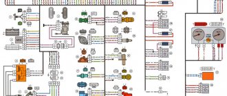
Wiring diagram VAZ-2129, 2130, 2131, 2329
1 — front lights; 2 – side direction indicators; 3 — electric motor for windshield washer; 4 — headlight washer motor*; 5 - switch; 6 – battery; 7 - starter; 8 – generator; 9 — VAZ-2129 headlights; 10 – gearmotors for headlight cleaners*; 11 – sound signal; 12 – spark plugs; 13 — carburetor limit switch; 14 — carburetor solenoid valve; 15 — ignition coil; 16 — windshield wiper gearmotor; 17 – carburetor solenoid valve control unit; 18 — ignition distributor sensor; 19 – coolant temperature indicator sensor; 20 – oil pressure warning lamp sensor; 21 – plug socket for a portable lamp; 22 – brake fluid level warning lamp sensor; 23 – windshield wiper relay; 24 – relay for turning on the rear fog light; 25 – relay for turning on the heated rear window; 26 – relay for turning on the headlight cleaners and washer; 27 – relay for turning on low beam headlights; 28 — relay for turning on the high beam headlights; 29 — ignition relay VAZ-2131; 30 – starter activation relay; 31 — relay-breaker for alarm and direction indicators; 32 — heater electric motor; 33 – additional resistor of the heater electric motor; 34 – backlight lamps for heater control levers; 35 – external lighting switch; 36 – main fuse block; 37 – additional fuse block; 38 – reverse light switch; 39 – brake light switch; 40 – instrument lighting regulator; 41 – ignition switch; 42 – three-lever switch; 43 – alarm switch; 44 – tailgate glass cleaner and washer switch*; 45 – heater motor switch; 46 – switch for heating the rear door glass; 47 – rear fog light switch; 48 – lamp switches located in the door pillars; 49 – interior lamps; 50 – Niva cigarette lighter; 51 – switch for the warning lamp for closing the carburetor air damper; 52 – control lamp for covering the carburetor air damper; 53 – switch for the differential lock warning lamp; 54 – parking brake warning lamp switch; 55 – sensor for level indicator and fuel reserve; 56 – instrument cluster; 57 – tailgate glass washer motor; 58 – rear lights; 59 – block for connecting additional brake lights; 60 – blocks for connecting side marker indicators; 61 – pads for connecting to the heated glass element of the tailgate; 62 – license plate lights; 63 – rear door glass wiper motor.
The order of conditional numbering of plugs in blocks:
a – windshield wipers, headlights and tailgate glass, windshield wiper relay breaker; b — ignition distributor sensor; c – relay-interrupter for alarm and direction indicators; d — switch VAZ-2131; d — three-lever switch; e — alarm switch; g – relay for turning on the rear fog light; h — rear lights (numbering of terminals in order from top to bottom); and – instrument clusters.
Instrument harness connection diagrams
List of elements of the electrical connection diagram of the instrument panel wiring harness assembly for cars of the LADA 4X4 family
1 - additional relay; 2 — relay-interrupter of direction indicators; 3 — windshield wiper relay; 4 — ignition switch; 5 — alarm switch; 6 — rheostat 2130; 7 — turn signal headlight switch; 8 — windshield wiper and washer switch; 9 — main fuse block; 10 — additional fuse block; 11 — instrument clusters; 12 — external lighting switch; 13 — rear window wiper switch; 14 — rear window heating switch; 15 — rear fog light switch; 16 — heater motor switch; 17 — additional resistor of the heater electric motor; 18 — heater electric motor; 19 — relay for high beam headlights; 20 — low beam headlight relay: 21 — rear window heating relay; 22 — rear fog light relay: 23 — cigarette lighter; 24 — differential engagement sensor; 25 — brake signal switch; 26 — reverse lamp switch; 27 — handbrake warning lamp switch; 28 — illuminator; 29 — illuminator; 30 — instrument panel harness block to the front harness: 31 — instrument panel harness block to the front harness; 32 — block of the instrument panel harness to the ignition system harness; 33 — instrument panel harness block to the rear harness: 34 — instrument panel harness block to the rear harness.
Where are the fuse and relay boxes located?
The electrical equipment system, electrical wiring and arrangement of safety blocks on the Niva 21214 and the modern Chevrolet Niva VAZ 2131 are identical. The electrical circuit of these machines has a main mounting block installed under the lower edge of the instrument panel casing in the area of the driver's left foot. An additional one is located under the main block.
A little to the left and below there is another additional block, in which inserts are installed that are responsible for the operation of the components of the fuel injection system. In addition to the fuses, there is a separate relay for controlling the wiper operation parameters and a set of relays for the engine control system.
When installing an injection engine on a car with an old wiring diagram, the designers had to install additional switching boxes.
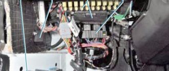
One of these blocks is located on the left side of the body near the main fuse box. Since the unit is installed in close proximity to the driver’s left foot, it is covered with a special protective plastic casing. The casing is fixed with two self-tapping screws for a Phillips screwdriver. The block itself contains a diagnostic connector and four fuses responsible for the operation of the engine and cooling system.
Block with cover removed
The relay responsible for turning on the engine starter can be installed separately in the engine compartment or next to the relay block. When installed under the hood, it is mounted on the compartment shield next to the brake fluid reservoir.
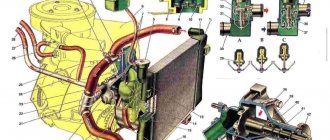
Niva car engine diagram
1 – oil level indicator; 2 – VAZ-2131 connecting rod; 3 – drain plug of the oil pan; 4 – oil pump; 5 – oil pump drive gear; 6 – oil pump drive shaft; 7 – crankshaft main bearing shell; 8 – crankshaft; 9 – front crankshaft oil seal; 10 – pulley fastening nut; 11 – crankshaft pulley; 12 – coolant pump drive belt; 13 – crankshaft sprocket; 14 – oil pump drive sprocket; 15 – generator pulley; 16 – camshaft drive cover; 17 – chain tensioner shoe; 18 – fan impeller; 19 – camshaft drive chain; 20 – exhaust valve; 21 – inlet valve; 22 – camshaft sprocket; 23 – camshaft bearing housing; 24 – camshaft; 25 – valve springs; 26 – cylinder head cover; 27 – oil filler cap; 28 – valve lever (rocker); 29 – adjusting bolt; 30 – cylinder head; 31 – coolant temperature indicator sensor; 32 – spark plug; 33 – cylinder head gasket; 34 – VAZ-2131 piston; 35 – rear oil seal holder; 36 – rear crankshaft oil seal; 37 – thrust semi-ring of the crankshaft; 38 – main bearing cover; 39 – VAZ flywheel; 40 – cylinder block; 41 – clutch housing cover; 42 – oil pan.
VAZ-213100 LADA 4×4 - engine 21214 engineer. 61.00 kW/83 hp catalyst, Euro-4, weight - 1425/max 1850 kg. (data from the car produced in 2012) hydraulic power steering, new “torpedo”, instrument panel 2115, front seats of the 12th series, plastic door trim and other changes. As of 2012, this version was the only one available for purchase through the AvtoVAZ retail network (among 5-door ones), while among the “short” ones there was a choice of configurations.
VAZ-213102 is a “civilian” modification with a 5-door body based on the VAZ-2131SP (213105). It was equipped with a five- or seven-seater (on request) interior. Trunk volume 1900 l. Produced to order in 2001-2005;
VAZ-213145 is a modification of the VAZ-2131SP with a VAZ-21214-20 (-30) injection engine that complies with Euro-2 (Euro-3) standards. Produced in small series since 2006.
Replacing the block
In case of burnout or mechanical damage, it is necessary to repair the unit by replacing its components or the entire assembly.
To replace the main unit, follow these steps:
- Disconnect the battery from the on-board network.
- Remove the box cover and unscrew the two 8 mm nuts securing the block. Then you need to pull the box towards you and remove it from the fastening studs.
- Write down the markings and position of the wires on the old unit.
- Disconnect the cables from the plugs of the old unit and connect them in the same sequence on the new one.
- Check fuse ratings and wire installation.
- Secure the replaced block with nuts.
- Connect power to the on-board network and check the functionality of the circuits.
The photo shows some stages of dismantling the block.
Other fuse or relay blocks on the VAZ 21214 are replaced in the same way.