The VAZ-2106 car was produced from 1976 to 2008. This guide provides color-coded wiring diagrams (for the injector and carburetor) with a description of all elements for various modifications. The information is intended for self-repair of the six. Electrical circuits are divided into several blocks for ease of viewing via a computer or phone; there are also circuits in the form of a single picture with a description of each element - for printing on a printer. All electrical equipment of a car can be divided into the following components:
- engine starting system;
- battery charge elements;
- fuel mixture ignition system;
- elements of external and interior lighting;
- sensor system on the instrument panel;
- sound notification elements;
- fuse block.
Electrical diagram of VAZ-2106 (old)
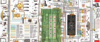
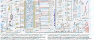
General diagram of the electrical equipment of VAZ 2106 / 21061 / 21063 / 21065 produced in 1976 - 1987.
1 – front lights; 2 – side direction indicators; 3 – battery; 4 – battery charge indicator relay; 5 – relay for turning on low beam headlights; 6 – relay for turning on the high beam headlights; 7 – starter; 8 – generator; 9 – external headlights; 10 – internal headlights; 11 – sound signals; 12 – electric motor of the engine cooling system fan; 13 – fan motor activation sensor; 14 – ignition coil; 15 – ignition distributor; 16 – spark plugs; 17 – carburetor solenoid valve; 18 – coolant temperature indicator sensor; 19 – engine compartment lamp; 20 – reverse light switch; 21 – oil pressure indicator sensor; 22 – sensor for low oil pressure indicator; 23 – indicator sensor for insufficient brake fluid level; 24 – windshield wiper gearmotor; 25 – windshield washer electric motor; 26 – relay for turning on sound signals; 27 – relay for turning on the fan motor; 28 – voltage regulator; 29 – windshield wiper relay; 30 – additional fuse block; 31 – main fuse block; 32 – relay-breaker for alarm and direction indicators; 33 – brake signal switch; 34 – plug socket for a portable lamp; 35 – heater electric motor; 36 – additional resistor of the heater electric motor; 37 – hours; 38 – heater motor switch; 39 – glove box lighting lamp; 40 – cigarette lighter; 41 – alarm switch; 42 – instrument lighting switch; 43 – warning lamp for insufficient brake fluid level; 44 – three-lever switch; 45 – ignition switch; 46 – rear fog lamp switch*; 47 – external lighting switch; 48 – lamp switches located in the front door pillars; 49 – switches for warning lights of open front doors; 50 – alarm lights for open front doors; 51 – lamp switches located in the rear door pillars; 52 – parking brake warning switch; 53 – interior lamps; 54 – fuel level indicator with reserve indicator; 55 – coolant temperature indicator; 56 – oil pressure gauge with low pressure indicator; 57 – tachometer; 58 – parking brake warning lamp; 59 – battery charge indicator lamp; 60 – carburetor air damper indicator lamp; 61 – side light indicator lamp; 62 – turn signal lamp; 63 – headlight high beam indicator lamp; 64 – speedometer; 65 – carburetor air damper warning switch; 66 – parking brake warning relay; 67 – rear lights; 68 – license plate lights; 69 – sensor for level indicator and fuel reserve; 70 – trunk lighting lamp; 71 – rear fog lamp*.
The order of conditional numbering of plugs in blocks:
a – windshield wiper and windshield wiper breaker relay; b – hazard warning and direction indicator breaker relay; c – three-lever switch.
Wiring diagram VAZ-2106 carburetor - full view:
Electrical diagram of VAZ-2106 (new)
General diagram of the electrical equipment of VAZ 2106 / 21061 / 21063 / 21065, produced 1988 - 2001.
1 – front lights; 2 – side direction indicators; 3 – battery; 4 – battery charge indicator lamp relay; 5 – relay for turning on low beam headlights; 6 – relay for turning on the high beam headlights; 7 – starter; 8 – generator; 9 – external headlights; 10 – internal headlights; 11 – fan motor activation sensor; 12 – electric motor of the engine cooling system fan; 13 – sound signal; 14 – ignition coil; 15 – ignition distributor; 16 – spark plugs; 17 – carburetor solenoid valve; 18 – coolant temperature indicator sensor; 19 – engine compartment lamp; 20 – reverse light switch; 21 – oil pressure indicator sensor; 22 – low oil pressure indicator sensor; 23 – indicator sensor for insufficient brake fluid level; 24 – windshield wiper gearmotor; 25 – switch*; 26 – electric motor for windshield washer; 27 – fan motor activation relay**; 28 – voltage regulator; 29 – windshield wiper relay; 30 – additional fuse block; 31 – main fuse block; 32 – relay-interrupter for alarm and direction indicators; 33 – relay for turning on the heated rear window***; 34 – brake light switch; 35 – plug socket for a portable lamp****; 36 – additional resistor of the heater electric motor; 37 – heater electric motor; 38 – heater motor switch; 39 – hours; 40 – glove box lighting lamp; 41 – cigarette lighter; 42 – alarm switch; 43 – instrument lighting regulator; 44 – brake fluid level indicator lamp; 45 – three-lever switch; 46 – ignition switch; 47 – rear window heating switch***; 48 – rear fog lamp switch; 49 – external lighting switch; 50 – lamp switches located in the front door pillars; 51 – gearmotors for electric windows of the front doors***; 52 – lamp switches located in the rear door pillars; 53 – parking brake warning lamp switch; 54 – interior lamps; 55 – fuel level indicator with reserve indicator; 56 – coolant temperature indicator; 57 – oil pressure indicator with low pressure indicator; 58 – tachometer; 59 – parking brake warning lamp; 60 – battery charge indicator lamp; 61 – carburetor air damper indicator lamp; 62 – side light indicator lamp; 63 – turn signal lamp; 64 – headlight high beam indicator lamp; 65 – speedometer VAZ-2106; 66 – carburetor air damper warning switch; 67 – power window switch for the left front door***; 68 – relay for turning on the electric windows of the front doors***; 69 – power window switch for the right front door***; 70 – rear lights; 71 – license plate lights; 72 – sensor for level indicator and fuel reserve; 73 – pads connected to the rear window heating element***; 74 – trunk lighting lamp; 75 – rear fog lamp.
The order of conditional numbering of plugs in blocks:
a – switch; b – ignition distributor sensor; c – windshield wiper and windshield wiper breaker relay; d – hazard warning and direction indicator breaker relay; d – three-lever switch.
* Installed if a vehicle uses a contactless ignition system. In this case, an ignition distributor sensor of type 38.3706 and an ignition coil of type 27.3705 or 027.3705 must be installed. ** Since 2000, it has not been installed and electric motor 12 is switched on directly by sensor-switch 11. In this case, instead of the previously used temperature sensor 11 of type TM-108, sensor-switch 661.3710 is used. *** Installed on car parts. **** Not installed since 2000.
Wiring diagram VAZ-2106 carburetor - full view:
General information about the brand
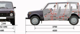
Domestic cars of the 2106 brand were manufactured for the purpose of operating on roads equipped with improved surfaces, regardless of weather conditions. The cars are equipped with a four-door all-metal sedan body.
Cars are equipped with carburetor gasoline engines, four-speed or five-speed gearboxes. There is an independent spring front suspension; The rear suspension is dependent spring. The car's braking system is dual-circuit; there are disc brakes on the front wheels.
The rear ones are equipped with drums. Cars of the VAZ 2106 family were equipped with radial tubeless tires. The steering column has an anti-theft device that is built into the ignition switch.
The modification range of the VAZ 2106 family includes:
- VAZ 2106, 21065-00 - equipped with a model 2106 engine;
- 21061, 21065-01 – equipped with a model 2103 motor;
- 21063 – there was an engine from 21011.
- Car brand 21065 is the luxury version of this family. It has the following differences from the 2106 model: it is equipped with a five-speed gearbox and a final drive with a gear ratio of 3.9. Some cars were equipped with a Solex-type carburetor and a contactless ignition system. The car's electrical equipment is complemented by an electrically heated rear window, halogen headlights and a rear fog lamp. The body has been modified: the upholstery and seat headrests have been updated; The car is supplemented with bumpers of the 2105 model. Spare parts for the presented vehicles are available everywhere. In addition, the electric power steering is a kind of “novelty”, so to speak, the trends of the 21st century are making themselves felt. Thanks to this, car maintenance and repairs are not a big problem.
Wiring diagram VAZ 2106 (injector)
1 controller 2 electric fan of the cooling system 3 ignition system harness connector to the left mudguard harness 4 ignition system harness connector to the right mudguard harness 5 fuel level indicator 6 fuel level harness connector to the fuel level sensor harness 7 oxygen sensor 8 fuel level sensor harness connector to the system harness ignition 9 electric fuel pump 10 speed sensor 11 idle speed control 12 throttle position sensor 13 coolant temperature sensor 14 mass air flow sensor 15 diagnostic block 16 crankshaft position sensor 17 canister purge solenoid valve 18 ignition coil 19 spark plugs 20 VAZ-2106 injectors 21 ignition system harness block to instrument panel harness 22 electric fan relay 23 controller power supply circuit fuse 24 ignition relay 25 ignition relay fuse 26 electric fuel pump power circuit fuse 27 electric fuel pump relay 28 ignition system harness block to injector harness 29 injector harness block to ignition system harness 30 block g guta instrument panel to the ignition system harness 31 ignition switch 32 instrument cluster 33 engine anti-toxic system display
Useful: VAZ 2110 diagram
Electrical circuit for switching on the electric motor of the engine cooling system fan
| Position number on the diagram | Explanation of the position on the diagram |
| 1 | magnetto |
| 2 | battery |
| 3 | Ignition switch VAZ 2106 |
| 4 | main fuse box |
| 5 | electric fan switch |
| 6 | electric fan switch sensor |
| 7 | electric fan |
| 8 | additional fuse block VAZ 2106 |
Injection engine control unit diagram
Electrical connection diagram for the injection engine control system:
1. — Controller connector. 2. — Mass air flow sensor. 3. — Coolant temperature sensor. 4. — Crankshaft position sensor. 5. — Throttle position sensor. 6. — Oxygen concentration sensor. 7. — Speed sensor. 8. — Ignition module. 9. — Electromagnetic valve for purge of the adsorber. 10. — Electric fan relay. 11. — Electric fuel pump relay. 12. — Main relay. 13. — Fuse protecting the power circuit of the electric fuel pump relay. 14. — Fuse protecting the power circuits of the main relay. 15. — Fuse link. 16 - Fuse protecting the constant power supply circuit of the controller. 17. — Diode. 18. — Idle speed regulator. 19. — Injectors. X1. — Diagnostic block. X2. — Connection block to the vehicle electrical system.
Schemes of individual six units
Generator connection diagram
1 — battery VAZ-2106; 2 — “six” generator set; 3 - regulatory device designed to control the operating voltage parameter; 4 - lock; 5 — plastic module with safety elements; 6 - control light indicator that determines the battery charge; 7 - relay that protects the power line of the battery charge indicator light.
Starter wiring diagram
1 — car starter device; 2 - battery; 3 - generator set; 4 - ignition switch.
Electrical circuits of the contact ignition system
1 — spark plugs; 2 - distributor; 3 — ignition switch; 4 - coil; 5 - switch; 6 - generator; 7 - battery.
Carburetor valve control circuit
1 - limit switching device of the carburetor unit; 2 - the engine valve itself; 3 - module used to control the carburetor unit; 4 — ignition coil; 5 - switching device; 6 - ignition switch, is a lock.
Wiring diagram of direction indicators and signaling
1 — lighting devices for turning lights installed in the front optical devices; 2 — battery VAZ-2106; 3 - car generator unit; 4 — side turning lights located on the front fenders; 5 — main mounting module with safety elements; 6 - auxiliary control unit with safety devices; 7 — ignition switch; 8 - device for turning off and activating the light signal, mounted in the car interior on the center console; 9 - switching device for activating and disabling turning lights; 10 - interrupting device used for blinking turning lights and light signals; 11 — speedometer, equipped with a control light indicator for activation of turning lights; 12 — light devices for direction indicators in the rear optics.
Electrical circuit for turning on the sound
1 - sound devices used to reproduce impulses; 2 - relay for activation of sound impulses, protects the electrical circuit from overvoltage; 3 — switch of sound pulses; 4 — mounting module with safety elements; 5 — generator set VAZ 2106; 6 - battery.
Switching diagram for electric windows
1 - main safety module; 2 - relay used to protect the power line of additionally installed power windows; 3 — switching device for the electric window mounted on the left door; 4 - a similar device used to adjust the position of the glass in the front right door; 5 — electric motor of the left glass lift; 6 — auxiliary module with safety elements; 7 - ignition switch.
Engine cooling system diagram
1 — generator unit, installed under the hood; 2 - battery; 3 - ignition switch or lock; 4 — main module with safety elements; 5 - relay that protects the power line of the activation system of the electric motor of the power unit cooling fan; 6 — ventilation device activation controller; 7 - the fan itself; 8 - auxiliary safety module.
Generator belt
Of course, the G-221 will not work without a drive belt. The belt for the VAZ 2106 generator is 10 mm wide and 940 mm long. It is wedge-shaped and toothed in appearance, which allows it to easily cling to the teeth of pulleys.
The belt resource is designed for 80 thousand kilometers.
The belt is made of high-strength rubber and is designed for a long period of operation.
How to tighten a belt
Tensioning the alternator belt after installing it is considered the final stage of work. For fast and high-quality work, you will need to comply with the factory tension regulations:
- Loosen the self-locking nut (on the top of the generator).
- Loosen the lower generator fixing nut.
- The body of the device should move slightly.
- Insert a pry bar between the generator housing and the pump housing.
- Move the pry bar to tighten the belt.
- Without releasing the mount, tighten the self-locking nut.
- Then check the belt tension.
- Tighten the bottom nut.
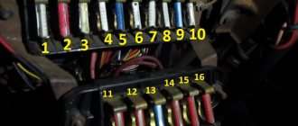
VAZ2107 fuse and relay diagram
The electrical wiring of the machine is protected by fuses, which are mainly installed in the central and additional units, located at the bottom of the instrument panel on the left side next to the steering column. The circuit from the battery to the terminals and connections is closed when the car ignition is turned on.
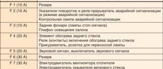
F1(16A) Klaxon, lamp socket, cigarette lighter, brake lamps, clock and interior lights (plafonds) F2(8A) Windshield wiper relay, heater and wiper motors, windshield washer F3(8A) Left headlight high beam and warning lamp on high beam F4(8A) High beam of the right headlight F5(8A) Low beam fuse of the left headlight F6(8A) Low beam of the right headlight and rear fog lamp F7(8A) This fuse in the VAZ 2106 block is responsible for the side light (left sidelight, right rear light), trunk light, license plate light right light bulb, instrument lighting lamps and cigarette lighter light F8(8A) Side light (right sidelight, left rear light), license plate light left light bulb, engine compartment lamp and side light warning light F9(8A) Oil pressure gauge with warning lamp, coolant temperature and fuel level indicator, battery charge warning lamp, direction indicators, carburetor choke indicator, rear window heating F10(8A) Voltage regulator and generator excitation winding F11(8A) Reserve F12(8 ) Reserve F13(8A) Reserve F14(16A) rear window heating F15(16A) Cooling system fan electric motor F16(8A) Turn indicators in hazard warning mode
Owners of 2106 should be aware that the old design of fuses has long become obsolete, since each time they operate they overheat, which affects the density of the cells. Lack of tight contact between the fuse and the connectors leads to their burning. Therefore, replacement of the fuse blocks is necessary. To avoid unnecessary problems with the electrical wiring, you should inspect the safety devices every six months. If the contact part burns, it is necessary to replace the fuses and clean the sockets. Today, many VAZ 2106 owners are modernizing classic blocks, replacing them with modern blade fuses.
Windshield washer does not function
Since not only the cleaner, but also the washer is responsible for the cleanliness of the windshield, it is worth considering the malfunctions of this device. The design of the mechanism consists of the following elements:
- washer pump;
- fluid reservoir;
- nozzles (jet);
- auxiliary parts (wiring, tubes).
The washer reservoir is located in the engine compartment and is held on a special bracket. Water or a special glass cleaning liquid is poured into it. The tank also contains a pump, through which the liquid is supplied through tubes to the nozzles, which spray it over the surface of the glass.
The washer reservoir is located under the hood, and a pump is installed inside the tank
Despite its simple design, the washer also sometimes fails and there may be several reasons for this:
- pump failure;
- fuse blown;
- kinking of tubes;
- breakdown of the steering column switch;
- poor contact on the power supply circuit.
Pump check
The washer pump on Zhiguli cars often does not work due to poor contact on the electric motor itself or wear of the plastic elements of the device. Checking the serviceability of the electric motor is quite simple. To do this, open the hood and pull the washer lever on the steering column switch. If the mechanism does not make any sounds, then the cause should be sought in the power circuit or in the pump itself. If the motor hums and fluid is not supplied, then most likely a tube has fallen off the fitting inside the tank or the tubes supplying fluid to the injectors have become bent.
A multimeter will also help you verify whether the pump is working or not. Using the probes of the device, we touch the washer contacts when the latter is turned on. The presence of voltage and the absence of “signs of life” of the motor will indicate its malfunction. Sometimes it happens that the device works and pumps, but due to clogged nozzles, liquid is not supplied to the glass. In this case, cleaning the injectors with a needle is required. If cleaning does not produce results, the part is replaced with a new one.
Washer nozzles are replaced due to a blockage that cannot be removed
If the fuse fails or the problem lies in the steering column switch, then these parts are replaced in the same way as described above.
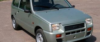
Modifications of the VAZ-2106 car
VAZ-21060 . Modification with the symbol VAZ-21060, Izhevsk assembly of recent years of production with a VAZ-21067 injection engine with a catalyst that meets the Euro-2 environmental standard
VAZ-21061 . Modification with a VAZ-2103 engine, some cars with a similar index were equipped with a simplified engine cooling system and did not have an electric fan. Instead, an impeller was installed on the end of the coolant pump shaft. Already Russian cars were equipped with bumpers from the VAZ-2105, some examples were equipped with cleaners and headlight washers.
VAZ-21062 . Export, right-handed modification of the base six.
VAZ-21063 . A car with an improved VAZ-21011 engine, with an oil pressure sensor and an electric engine cooling fan. The release of this modification was completed in 1994.
VAZ-21064 . Export, right-handed modification, like the VAZ-21062, but the VAZ-21061 modification was taken as the basis
VAZ-21065 . A modification of the car with improved equipment, which was produced from 1990 to 2001. An engine with a volume of 1569 cm3 was installed as a power unit. Other differences from the base model include a more powerful generator, a 5-speed gearbox, a rear axle gearbox with a gear ratio of 3.9, a contactless ignition system, and a Solex carburetor. There were other changes both in the exterior and in the interior, in general it was a “luxury” version of the VAZ-2106 sedan.
VAZ-21065-01. The same VAZ-21065 but with a VAZ-2103 engine
VAZ-21066 . Export, right-hand drive modification of the VAZ-21063 car.
VAZ-21068 . A car that was produced as a carrier of units during the development period of the new VAZ-2108 and VAZ-21083 engines.
VAZ-21069 . Modification of the VAZ-2106 manufactured by order of the special services. It was equipped with a two-section rotary piston engine VAZ-411 with a power of 120 hp, VAZ-413 with a power of 140 hp.
General tuning aspects
The simplest tuning of the VAZ 2106 dashboard is to purchase a ready-made set of accessories and replace standard devices. You can install it yourself using the instructions included with the kit. More labor-intensive is the tuning of individual devices, which involves replacing stickers and arrows.
When changing arrows and stickers, you need to be careful, as these parts are very fragile.
Tuning the VAZ instrument panel can be done by replacing the meter dials with white ones and installing overlays on the panel. You can cover the panel with artificial leather or leather if you have sufficient funds. Before stretching the material, the surface of the shield must be cleaned and then adhesive must be applied in an even layer. Next, press the leather or substitute over the entire surface and wait until the glue dries. At the last stage, you need to process the edges, giving it an aesthetic appearance.