Messages 7
1 Topic by Admin 2013-07-05 13:09:37
- Admin
- Administrator
- Inactive
- Registration: 2012-02-20
- Messages: 3,257 Thanks : 624
Topic: Is it possible to connect the light control module from Priora to a VAZ 2110?
Ideally, I would like to get a working connection diagram for this module instead of the standard “decimal” ones that are on the instrument mask.
2 Reply from Serg 2013-11-02 14:17:26
- Serg
- Lada2111.rf fan
- Inactive
- Registration: 2013-07-29
- Messages: 830 Thanks : 363
- Car: 2111 dwg 2114 year 2008
Re: Is it possible to connect a light control module from Priora to a VAZ 2110?
Connecting a light control module from Priora
We have a module with one 12-pin connector (No., color in prior) wire purpose (function) 1 - orange-black - input indicating that the rear foglights are on 2 - orange-white - output controlling the activation of the rear + front foglights 3 - yellow - input indicating that the front ones are on prottumanok 4 - brown - output control the brightness of the backlight of the buttons 31 - black - ground (it is also mass in Africa) 30 - pink - input +12volts from the battery 56 - green - output +12volts turn on the head light 58 - whitechern - output +12volts turn on dimensions 56v - serkras - +12 volt input after turning on the head light to control the fog light 58v - white - input for the illumination of the Xz - synchern - +12 volts after the ignition switch G - blue - to control the headlight range control
56 Xz 31 58b 56b G 30 58 4 3 2 1
After comparison with the 2110-2112 scheme, the following came out:
1) it is possible to connect this unit without an electrical package control unit Priors without foglight controls (I will finalize it later) all other wires somehow match in color (.) must be connected to the connector (standard 2110) light control except for the following wires: 1 – orange-black, 2 – orange white, 3 – yellow, 4 – brown (use standard regulator 2110), G – blue (if you want to connect the headlight range control, knock on the priors)
2) it is possible to install a control unit for the Priora electrical package (but later)
3 Reply from Admin 2013-11-13 13:45:45
- Admin
- Administrator
- Inactive
- Registration: 2012-02-20
- Messages: 3,257 Thanks : 624
Re: Is it possible to connect a light control module from Priora to a VAZ 2110?
That is, here are the contacts of the ICC Priora that should be used? 31- black - ground (it is also mass in Africa) 30- pink - input +12 volts from the battery 56- green - output +12 volts turns on the head light 58- belchern - output +12 volts turns on the headlights 56v-serkras - input +12 volts after turning on the headlight light for control fog 58V - white - input to the Xz block illumination - synchern - +12 volts after the ignition switch
Here is the standard switch for the low beam and dimensions of the old-style instrument panel (on diagram No. 36)
30 (pink) - connect to 56 (green) 58 (white-black) - connect to 31 (black) 56 (green) - connect to 58 (belchern) X (blue-red) - this is also a mass.
I found the remaining contacts in the VAZ 2110 mounting block: Ш3-4 (+12V) - connect to 30 (pink) Ш3-1 or Ш3-3 - connect to 56V (serkras) Ш2-8 - connect to 58V (white) Ш1-4 and Ш4-17 - connect to Xz (synchern) Is that right?
I looked at the contacts from the mounting block here
4 Reply from Serg 2013-11-13 16:20:04 (2013-11-13 16:50:09 edited by Serg)
- Serg
- Lada2111.rf fan
- Inactive
- Registration: 2013-07-29
- Messages: 830 Thanks : 363
- Car: 2111 dwg 2114 year 2008
Re: Is it possible to connect a light control module from Priora to a VAZ 2110?
No, it’s not right on the standard light switch 2110 to connect all the wires in the same colors with the Priora IUS, something like this
Priora 2110-212 30 (pink) - connect to 30 (pink) 58 (white-black) - connect to 58 (belcher) 56 (green) - connect to 56 (green) X (blue-red) - X (blue-black) +12 volts after the ignition switch
The wires of the MUS Priors 1 - orange-black, 2 - orange-white, 3 - yellow, have a trigger switch (i.e. pressed once, turn on a second time, turn off) the triggers are located in the Priora's electrical package unit, so simply connecting them to 2110 will not work, you need to come up with a diagram
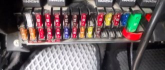
Circuit breakers
This is the second most common cause of low beam failure. If the left headlight does not light, then it is worth inspecting fuse F6.
Where is he located? It is located in a block hidden under the steering wheel. To get there, you need to remove the protective cover, which is held in place by three clips.
When the right light fixture does not function, look at fuse F7.
The protective devices mentioned above have the same rating - 7.5 amperes. The easiest way is to replace the damaged fuse with a working one. If one is not at hand, then as a temporary measure a “bug” is installed, that is, a jumper made of any suitable piece of copper or aluminum wire. In a pinch, even regular foil will do.
It is worth knowing that frequent blown fuses clearly indicate problems with the wiring. As a rule, a malfunction here often occurs due to the fact that the insulation of current-carrying elements is frayed. It is important to find the defective location and insulate it as soon as possible, since the occurrence of a short circuit leads to a fire in the vehicle.
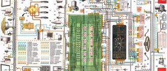
Electrical circuit diagram of the lighting control module of the VAZ 2170 (Priora).
Electrical circuit diagram of the lighting control module of the VAZ 2170 (Priora).
Module diagram.
Module pinout.
Contact
| Purpose | |
| 1 | Indicator signal for turning on the rear fog lights |
| 2 | To the rear fog lamp relay |
| 30 | + 12 V (battery terminal 30) |
| 31 | Frame |
| 56 | To the headlights |
| 58 | To side lights |
| 58b | To sources of illumination of controls and instruments |
| G | To gear motors for headlight range control |
| Xz | + 12 V (terminal 15) |
| 3 | Warning signal for turning on fog lights |
| 4 | To the fog light relay |
| 56b | To the automatic headlight control system controller |
1 Symbols and index - white with light green backlight. 2 The position of the key or wheel is not fixed. 3 The color of the control indicators when not illuminated is uniform gray, turning to black; in the illuminated state: – yellow, for the rear fog lamp switch; – green for the front fog lamp switch. 4 Symbols on the electrical diagram: A1 – instrument lighting regulator; A2 – headlight range control switch; A3 – external lighting switch; A4 – front fog lamp switch; A5 – rear fog lamp switch; ХL1_ ХLn – LEDs for illuminating symbols (symbols); XL2 – LED illumination of the indicator of the outdoor lighting switch; XL3 – LED illumination of the control indicator for turning on the rear fog lights; XL4 – LED illumination of the indicator light for turning on the front fog lights.
Content
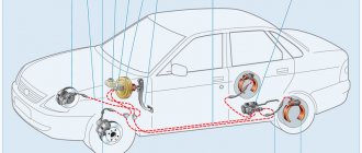
The low beam of the headlights does not light up, but the high beam is on - this phenomenon can be due to several reasons. And most of them are quite easy to fix. Moreover, this can happen to your car at a completely inopportune moment: on the highway, for example, when you need to switch to low beam so as not to blind oncoming drivers with headlights. Let's try to deal with all the flaws one by one, and consider: what might be the most common options for repairing and troubleshooting such an important segment as low-beam lighting.
Schematic diagram (pinout) of connecting the front wiring harness on the Priora
The front part of the vehicle's electrical circuit is designed to supply voltage to the primary and auxiliary power circuits of the vehicle's on-board systems. The decoding of contact group chips is as follows:
- 1 – starter power supply;
- 2 – battery;
- 3 – charge supply from the generator;
- 4 – connecting block for the bundle (1 – 3);
- 5-7 – power supply to the device;
- 8 – engine compartment lighting lamp;
- 9-10 – head light;
- 11 – brake expansion tank level indicator;
- 12 – outside temperature;
- 13 – washer drive;
- 14 – external indication of reverse gear;
- 15 – cooling system fan;
- 16 – stove reducer;
- 17 – reserve resistor;
- 18 – wiper drive;
- 19 – interior relay and fuse module;
- 20 – stove motor;
- 21 – sound alarm indicator;
- 22 – horn power supply;
- A1/2, B1/2 – mass.
We install xenon with our own hands
Do not neglect safety precautions when installing xenon, as you can not only damage the equipment, but also seriously injure yourself. So make sure your hands are dry and oil-free.
It is also forbidden to touch the xenon lamp bulb with your hands. In case of contact with it, it is necessary to degrease the surface with alcohol.
Once you are convinced that the process is safe, you can proceed directly to the installation. First of all, we will remove the old halogen lamps and replace them with xenon lamps. To do this, you need to remove the protective cover from the headlights. Disconnect the contact wires from the lamp and take it out. In order to safely remove the light bulb in some cars, you need to release the spring that secures it. We carefully remove the new xenon lamp from the protective bulb and insert it into the hole. Remember not to touch the flask with your hands. If you had a spring that fixed the halogen lamp, then you need to crush it. The fact is that the wires from the xenon lamps will need to be pulled through it and then brought out through a plug into the engine compartment. From the battery side, this will be a little more difficult to do, since it will partially block access to the headlight. Therefore it is better to remove it. After installing the bulbs, connect the terminals from the ignition unit to them. The next step is to make holes in the headlight plugs to run the wires through. There are two types of plugs - rubber and metal. We cut out a hole in rubber ones with scissors; in metal ones we will have to drill. It is better to use a milling cutter for drilling. The optimal hole diameter is approximately 25 mm. The stage of installing the light bulbs was the most difficult and time-consuming. Next, you need to select a location to install the ignition unit. It should be located in close proximity to the headlights so that the wires do not pass under tension. It is better to choose a place that is protected from moisture, dirt and heat. In general, high-quality ignition units should be sealed, but some manufacturers take little care of this. If you still cannot find a protected place, then simply wrap the block with electrical tape or tape. This will increase his safety, albeit partially. The ignition unit itself can be secured using clamps, double-sided tape, or attached with screws. Next, we connect the wires from the ignition unit and from the xenon lamps. Here, each wire has its own color, so it will be difficult to mix it up. You also need to connect the ignition unit to the standard electronic system. To do this, we draw another wire from the ignition unit to the connector where the halogen light bulb was connected. We repeat the procedure with the second headlight, the process is similar - we install xenon lamps, an ignition unit and connect the wires. We secure all the wiring with clamps so that it does not dangle. the excess wire into a ring.
It is better to check the correct connection using the diagram, which will definitely be in the instructions. You can also use this xenon connection diagram: Some difficulties arise when installing xenon with your own hands on cars with on-board computers. If the xenon does not function correctly when igniting or during lighting, it is recommended to install a voltage relay. It will stabilize the load on the wiring at the moment when the headlights turn on.
This video explains how to install xenon lamps with your own hands. Lamps manufactured by IL-Trade, color temperature 4300K with H7 base.
VAZ 2170 ECM harness connection diagram
This part is organized to supply power to the main instruments and engine control system of the Lada Priora. From here, voltage is supplied to the main components, units of the vehicle’s power plant, as well as control sensors and ECUs. The standard electrical circuit connection system (pinout) looks like this:
- 1 – ECU power supply;
- 2 – main block of the electronic system to the dashboard;
- 3 – distribution board;
- 4 – speedometer;
- 5 – road surface roughness sensor;
- 6 – indication of pressure in the engine crankcase;
- 7 – TPS;
- 8 – DTOZH;
- 9 – indication of antifreeze temperature sensor;
- 10 – mass air flow sensor;
- 11 – control XX;
- 12 – main relay of the fuel pump;
- 13 – VT circuit fuse;
- 14 – relay BZ;
- 15 – fuse of the above circuit;
- 16 – ECU fusible link;
- 17 – DPKV;
- 18 – power supply for mass air flow sensor;
- 19 – phase distribution;
- 20 – mixture detonation sensor;
- 21 – EMC for purging the adsorber;
- 22 – diagnostics of the air flow sensor;
- 23 – power supply to the ignition coil;
- 24 – supply voltage to spark plugs;
- 25 – power supply to fuel injectors;
- 26 – terminal from the ignition coils to the ECM;
- 27 – feedback from 26;
- 28 – ECM connector to the injection system;
- 29 – response to the previous output;
- A – phase on the battery;
- B1/2 – ignition mass;
- C1 – mass from short circuit.
Other reasons
Sometimes the high or low beam fails due to the fact that the car owner thoughtlessly makes changes to the electrical circuits of his vehicle, without having a proper understanding of their operation. If such interference took place, then you should carefully analyze your actions and check what exactly was done wrong.
When none of the above recommendations helped fix the problem, it would be better to contact a car repair shop, since, most likely, attempts to search will lead to an even worse situation. In this case, you will subsequently need much more money to eliminate the fruits of your inept actions.
Interpretation of the symbols for the rear wiring harness of the VAZ Priora
The rear part of the electrical wiring chain is responsible for the vehicle's lighting and peripheral systems. This includes lights, locks and windows. The pinout of tips and terminals looks like this:
- 1 – dashboard response;
- 2 – power supply for the door behind the driver;
- 3/28 – power supply for the front passenger panel equipment;
- 4 – maintenance of power windows and door locks;
- 5-6 turn signals;
- 7 – interior lighting;
- 8 – handbrake indication switch;
- 9-10 – aft dimensions;
- 11 – temperature inside the car;
- 12-15 – circuit breakers for lighting the interior of the machine;
- 16/17 – power supply to the devices of the aft right and front left doors, respectively;
- 18/19 – voltage to the rear right and left speakers, respectively;
- 20 – cigarette lighter power core;
- 21 – EBN;
- 22 – contact group of the cargo compartment lighting circuit breaker;
- 23 – heated rear windshield;
- 24 – luggage compartment lighting lamp;
- 25 – additional stop;
- 26 – power line to the electric lock of the luggage compartment lid;
- 27 – power supply for rear number plate illumination;
- A1-4 – mass;
- ХР1/3 – electrical package power controller.
Pinout for rear license plate illumination of VAZ 2170
The small harness, located in the luggage compartment, has only three terminals:
- 1 – power supply to the stern license plate lights;
- 2-3 – license plate lighting lamps;
- 4 – trunk lid lock motor.
Pinout for the driver's door of the Priora
The harness is routed to supply power to the driver's door equipment. There is an output to the key panel installed in the armrest. There are six elements in total:
- 1 – additional terminal to the rear of the machine;
- 2 – line to the left fuse;
- 3 – electric window drive;
- 4 – armrest control module;
- 5 – door lock drive;
- 6 – rear view mirror control chip.
Burnt out light bulbs
The halogen lamps that the headlights are equipped with have two filaments. The first is responsible for the high beam, and the second for the low beam.
Read more: Replacing the hydraulic corrector for headlights on a VAZ 2114
If one of them is destroyed, the other will most likely burn normally. This is important to keep in mind when starting to troubleshoot.
Burnout is also indicated by the following circumstance - for example, there is no light in the left headlight, while the right device is working normally.
Replacing the light bulb is very easy. The procedure is as follows:
- open the hood;
- remove the headlight protection;
- disconnect the power connector;
- unfasten the fixing springs;
- take out the lamp;
- insert a new one.
It is important to remember that halogen appliances require careful handling. Traces of fat on the flask usually lead to their rapid failure - therefore, before installation, the glass surface is wiped with alcohol or acetone.
It is necessary to wear gloves when working with lamps - this will keep their surface clean.
Electrical diagram of the dashboard (Torpedo) VAZ-2170 Priora
Part of the on-board network is designed to power the main group of vehicle equipment. The control and display elements of the instrument panel are concentrated here. The wiring supplies power to loaded parts and critical components:
- 1-3 – contact group of the front harness;
- 4 – supply voltage to the aft connector;
- 5 – power supply from the fuse panel;
- 6 – contact group of stops;
- 7 – instrument panel indication;
- 8 – control of illuminators;
- 9 – contact group of emergency airbags;
- 10 – horn;
- 11 – power supply of the diagnostic unit;
- 12 – on-board PC control;
- 13 – ignition coil controller;
- 14 and 15 – supply voltage to the EUR control unit;
- 16 – control of power window equipment;
- 17 – alarm relay;
- 18 – wiper regulator;
- 19 – air flow distributor for the ventilation system;
- 20 – stove;
- 21 – heater drive;
- 22 – heated rear wind window;
- 23 – onboard clock;
- 24-25 – radio connection;
- 26 – emergency warning button;
- 27 – glove compartment lighting;
- 28 – control button for the glove box illumination;
- 29 – bundle of wiring for ignition;
- 30 – to the emergency airbag control board.
Lamps used in the Lada Priora car
For reasons of safety of drivers, passengers and pedestrians, the Traffic Rules and the Technical Regulations on the Safety of Wheeled Vehicles prohibit the operation of vehicles whose external lighting devices do not meet the design requirements of the vehicle. After all, on the one hand, it is necessary that the car is clearly visible on the road, and on the other hand, it is dangerous to blind other drivers or pedestrians with too bright or incorrectly adjusted headlights. Working brake lights will allow drivers moving behind you to keep a safe distance. There are many such nuances, and everyone can save not only money and nerves, but often also health.
Pinout of the instrument panel VAZ 2170 Priora
The layout of the instrument panel is made in a simplified version to facilitate the replacement and installation of replacement parts. The decoding of the wiring connections at the factory terminals looks like this:
- 1 – EUR;
- 2 – emergency signal control;
- 3 – oil pressure sensor;
- 4 – indicator light for turning on the hand brake;
- 5 – immobilizer control unit;
- 6 – control unit for airbags;
- 7 – external lighting of the car;
- 8-9 – direction indicators;
- 10 – control of the combustible mixture injection system;
- 11 – disabling the front passenger SB;
- 12 – indication of seat belt buckles;
- 13 – operation of the brake system;
- 14 – reset button of the steering column switch;
- 15 – indication of the expansion tank of the brake system;
- 16 – ABS control unit;
- 17 – headlight high beam position switch;
- 18 – dashboard lighting;
- 19 – mass;
- 20 – receiving power from the battery terminal;
- 21 – ignition switch connector;
- 22 – fuel consumption sensor;
- 23-24 – BC mode switch;
- 25-26 – temperature sensor “overboard”;
- 27 – remaining fuel in the tank;
- 28 – speedometer;
- 29 – antifreeze temperature indication;
- 30 – tachometer;
- 31 – diagnostic terminal;
- 32 – power supply from generator (L).
Layout of the restyled version
in Priora after restyling - small details invisible to the eye, the center console, the dashboard. The headlights have also changed - they have become quite a bit larger. The principle of their design has remained virtually unchanged, except that there is now one plug at the back to isolate the contacts.
The design of the headlamp unit has become more complex: now in place of the usual high beam lamp there is a light consumable, combined with daytime running lights, which switches between operating modes. PTF fog light bulb, everything is also mounted depending on the configuration.
Tuning and replacement of the center console on Lada Priora and Kalina
Modern versions of cars are supplied to the market with a restyled version of the tidy. Here, a relatively old generation, navigation and a liquid crystal display appeared. Installing an updated shield requires the following steps.
Selecting the required version
There are only two types of updated designs with and without a CAN bus. The nuance is that the versions are completely identical in appearance. In order to find out which variety is suitable, you need to check the production date of the car. Machines manufactured before 06, 2012 are not equipped with this technology. The article numbers for the new devices with navigation are as follows:
- 2170-3801010-50 without CAN;
- 2170-3801010-60 with CAN.
Also in the kit you need to purchase a navigation antenna and a steering column switch of the appropriate design.
Installation nuances
For Lada Kalina versions, all devices are not equipped with a CAN module. Also the old generation of Priora. Here the installation is carried out without modifications or nuances - just snap out the old panel, remove the terminals, and mount the new set on the stock fasteners. Next, you need to install a navigation antenna on the roof and connect it to the appropriate connector. The second case is when an old panel with a CAN unit, but without navigation, is replaced with an analogue one. Here it is necessary to rearrange the contact connectors of the standard wiring from positions 10-11 to sockets No. 28-29. In case of incorrect operation of the devices, the replaced wires are swapped with each other. After the repair is completed, the counters should reset to zero.
LADA Priora lamp base
Regardless of the year of manufacture of the Lada Priora, three types of lamps are traditionally used in the head optical system:
- Low beam.
- Long-distance lighting.
- Side lights.
However, regarding the category under consideration (high beam), copies released before 2013 and after were equipped with different types of lamps:
- Pre-styling - H1 55W.
- Restyled – H15 55W.
With the same power of 55 watts and a single-filament structure, the type of base has changed from H1 to H15 (the DRL function has been added). At the same time, the modification of the light generator remained the same - halogen. In addition, the changes affected the design of the headlamp itself, which is clearly shown in the following images:
Note! Halogen lamps that are part of the Lada Priora lighting system should not be touched with unprotected, clean cotton gloves. Traces of grease and dirt left behind will lead to their rapid failure. To remove existing deposits from the surface of the glass, you can use a cotton swab soaked in alcohol.
Lighting repair
In some cases, owners need to disassemble and repair the headlight due to a malfunction of its components, to replace glass, with regular formation of condensation, or for tuning:
- We dismantle the lantern.
- The headlight unit consists of two parts connected with glue or sealant. Use a hairdryer to heat the joint around the circumference until the glue becomes softer.
- Separate the glued parts from each other with a screwdriver, cutting the glue with a mounting knife and continuing heating. On Bosch headlights, remove the four latches.
- We clean the disassembled parts from glue with a mounting knife and sandpaper.
- Upon completion of the repair, glue the separated parts together with sealant.
Then you need to wrap the headlight with plastic film and tape and leave until the sealant polymerizes.
Pre-styling Lada Priora
| Name | Manufacturer country | Characteristics and Features | on a 5-point scale |
| Bosch Gigalight | Hungary. | Fairly bright white light. 120% power compared to standard. | 5 |
Adjusting the lights
Properly adjusted headlights are the key to safe driving at night. Good road lighting helps you avoid an obstacle, a pothole, or an open hatch in time, notice a pedestrian in a timely manner, and avoid a collision with a vehicle parked incorrectly on the side of the road.
Factory adjustment minimizes the harm caused by bright lights to oncoming drivers. After replacing lighting fixtures or body repairs, situations arise when they need to be adjusted. If you have the tools and a suitable place, it is not difficult to do it yourself.
- flat surface (opposite a wall, garage or gate);
- five-meter tape measure;
- a sheet of thick paper that does not allow light to pass through;
- hex wrench.
READ What oil to pour into Priora 16
A diagram is drawn on a vertical surface that acts as a screen. At the level of the center of the headlights, draw a horizontal line. We put the parallel line 65 mm lower. We apply vertical marks opposite the centers of the right and left lamps, as well as in the middle, at an equal distance from them. We bring the car into equipped condition (there is no excess cargo, the tank is filled). We bring the tire pressure level to the nominal value. Further:
- We place the car 5 meters from the screen, the centers of the headlights are located opposite the corresponding vertical marks.
- We set the electric corrector drive for the lights to “0”, which corresponds to the minimum vehicle load.
- We load the driver's seat with a load of 75 kg and rock the car to install the suspension.
- Open the hood, turn on the low beam, and use paper to block the light from the right light fixture.
- Using the left headlight adjustment screw, using a hex wrench, adjust the horizontal border of the light to the bottom mark.
- We bring the bend of the light border to a vertical mark corresponding to the center of the lantern.
- We set the right headlight in the same way.
Replacing headlight bulbs on a car manufactured after 2013
Headlight unit for Lada Priora produced after 2013: 1 - electrical connector; 2 — headlight beam control in the vertical plane; 3 — protective cover of lamps; 4 — direction indicator lamp socket; 5 - regulator of the headlight beam in the horizontal plane.
Headlight unit for Lada Priora produced after 2013: 1 - electrical connector; 2 — headlight beam control in the vertical plane; 3 — protective cover of lamps; 4 — direction indicator lamp socket; 5 - regulator of the headlight beam in the horizontal plane.
Headlight unit for Lada Priora produced after 2013: 1 - electrical connector; 2 — headlight beam control in the vertical plane; 3 — protective cover of lamps; 4 — direction indicator lamp socket; 5 - regulator of the headlight beam in the horizontal plane.
We demonstrate the work on the left headlight unit (for clarity, the work is shown on a removed headlight unit), and change the lamps in the right headlight unit in the same way.
It is more convenient to perform operations to replace lamps in the left headlight unit with the battery removed. To replace the turn signal lamp
turn the lamp socket counterclockwise.
turn the lamp socket counterclockwise.
turn the lamp socket counterclockwise.
and remove the lamp socket from the headlight housing.
and remove the lamp socket from the headlight housing.
and remove the lamp socket from the headlight housing.
Pressing the lamp, turn it all the way counterclockwise and remove the lamp from the socket.
Pressing the lamp, turn it all the way counterclockwise and remove the lamp from the socket.
Pressing the lamp, turn it all the way counterclockwise and remove the lamp from the socket.
The cartridge is sealed in the headlight housing with a gasket. If the gasket is torn or has lost elasticity, replace it with a new one.
Install the new PY21W lamp in the reverse order. In this case, two protrusions, located asymmetrically relative to the axis of the lamp, must fit into the corresponding grooves of the socket.
turn the spring lock of the cover.
turn the spring lock of the cover.
turn the spring lock of the cover.
Remove the headlight cover by removing its hooks from the hinges on the headlight body.
Remove the headlight cover by removing its hooks from the hinges on the headlight body.
Remove the headlight cover by removing its hooks from the hinges on the headlight body.
Turn the high beam lamp with daytime running light function counterclockwise.
Turn the high beam lamp with daytime running light function counterclockwise.
Turn the high beam lamp with daytime running light function counterclockwise.
We install the new H15 lamp in the reverse order.
We release the three spring clips of the low beam lamp.
We release the three spring clips of the low beam lamp.
We release the three spring clips of the low beam lamp.
Disconnect the ends of the two wires from the contacts of the low beam lamp.
Disconnect the ends of the two wires from the contacts of the low beam lamp.
Disconnect the ends of the two wires from the contacts of the low beam lamp.
We install the new H7 lamp in the reverse order.
By pulling, we remove the socket with the side light lamp from the headlight housing.
By pulling, we remove the socket with the side light lamp from the headlight housing.
By pulling, we remove the socket with the side light lamp from the headlight housing.
We install the new W5W lamp in the reverse order.
Signs and causes of headlight malfunctions, ways to eliminate them
The main reason for replacing optics is the cessation of performing its functions - reliable road lighting - or failure:
- the headlight fogs up, ventilation is impaired;
- deep cracks or chips in the glass;
- reflectors are faulty;
- electrical connectors are faulty;
- fastening elements are broken.
Replacing faulty elements allows you to restore the original properties of the lighting device, increasing the degree of driving safety for both the driver and other road users.
The headlights on the Lada Priora have a non-separable design. To change glass, a faulty element, or carry out tuning, you have to either replace the headlight with a new one, or, showing ingenuity, disassemble the standard one. Tools for dismantling and repair:
- cross-head screwdriver;
- key to “10”;
- industrial dryer;
- mounting knife;
- fine-grain sandpaper;
- scotch;
- polyethylene film;
- sealant.
Headlights play a significant role in car design. In case of repair, tuning or replacement with an identical analogue, it is necessary to indicate the procedure for dismantling and subsequent installation. To replace the headlights, you will need a 10mm wrench and a Phillips screwdriver. Step-by-step instruction:
- Disconnect the negative terminal from the battery.
- Remove the front bumper.
- Disconnect the connector with the wires from the headlight by releasing the latch.
- Unscrew the lower front bolt and the side screw of the headlight.
- Unscrew the screws and remove the casing.
- Unscrew the upper mounting bolt.
- We remove the headlight.
Installation of the lamp is carried out in the reverse order. Replacing taillights is slightly different:
- Disconnect the negative terminal of the battery.
- Unfold the trunk trim covering the canopy.
- We press out the clamps.
- Disconnect the connector with wires from the rear light.
- After unscrewing the fastening screw, bend the trunk trim.
- Unscrew the three wing nuts.
- We remove the headlight.
Install the rear light in the reverse order.
LADA Priora - bulb replacement
Replacement of low beam light , LADA Priora.
- Installation of xenon and LED lamps requires the installation of ignition units, and also contains a number of other features. Which low beam lamp is on the Ford Focus 2: which one is better to choose, article number, type, diodes Well-maintained and well-equipped optics. Replacing a low beam lamp on a Renault Logan: photos and. In particular, LED bulbs require the installation of a large reflector and a cooling system. Therefore, it will not be possible to do the installation yourself;
- The lamp ignites gradually, so the low beam turns on with some delay.
Advice! To avoid problems when driving in bad weather under the light of xenon or LED lamps, you should install fog lights with halogen lighting elements.
For these reasons, the low beam lamp on the LADA Priora is selected individually, depending on the financial capabilities of the car owner, the region and the weather in which the car is most often planned to be used. The best low and high beam lamps for the Lada Priora. However, it should be noted that halogen lighting elements are still the most popular.
Types of front and rear headlights for Lada Priora
Low and high beams, as well as turn signals and side lights on Lada Priora cars are structurally combined into block headlights. The built-in electric corrector allows the driver to adjust the height of the light beams from his seat, depending on the degree of loading of the vehicle.
The main manufacturers of Priora headlights are Bosch and JSC Avtosvet Plant in Kirzhach. At first glance, one gets the impression that the models are absolutely identical, but there are a number of differences - the location of the side lamps, the design and shape of the reflectors, the presence of a chrome cut on the turn signal magnifier.
The shape and number of plugs differ. The headlight units are equipped with:
- low beam lamp - H7;
- high beam lamp - AKG12–55–2 (H1);
- high beam lamp and DRL – H15;
- turn signal lamp – A12–21–4 (PY21W);
- side light lamp – A12–5–2 (W5W).
READ Kia sportage x-pro 2023: light SUVs
All types of conventional automotive single-filament and double-filament incandescent lamps are currently available in halogen versions. Lamps H1, H3, H4, H7 have good lighting characteristics and low cost, which allows you to create optimal lighting.
Bosch xenon lamps are in high demand due to their long service life and high-quality light. The rear lights structurally combine parking lights, fog lights, turn indicators, brake lights and reversing lights
- direction indicator – А12-21-3 (P21W);
- side and fog light – P21/4W;
- brake light – A12-21-3 (P21W);
- reversing light – A12-21-3 (P21W).
The color of the wires corresponding to each socket is indicated on the flashlight body.
Since 2013, new LED lights have been installed as taillights on Priora 2. The manufacturer has established a warranty period of 24 months for all lighting and electrical equipment, provided the client complies with the rules of their operation and performs scheduled maintenance.
Table of the best models and manufacturers
Among the highest quality, reliable and durable (400-1600 hours) lamps for the Priora car, models from manufacturers such as Osram, Philips and Bosch stand out. Let's consider their features and characteristics for the pre-restyling and restyled versions of the Lada 2170.
Pinout of the lighting control unit on Priora
The module is connected to the vehicle’s on-board network via chip No. 1118-3724500. The standard terminal pinout on a VAZ 2170 looks like this:
- G56b – for the gearbox for adjusting head lighting devices;
- 58b – output from lighting and instruments;
- 31 – neutral earth cable;
- Xz – 12 volts from pin 15 of the ignition switch;
- 56 – relay switch for high and low headlight modes;
- 1, 3 – connection of fog lights;
- 2, 4 – sending a signal to the controller;
- 58 – dimensions;
- 30 – power supply from the ignition switch design.
POST REPAIR PROCEDURES
After the new VAZ 2114 low beam bulb is installed, it is necessary to check the assembled headlight unit for leaks. If it is not there, then the headlights will at least fog up, and at most dirt, dust and water will get inside them when it rains.
In addition, you should not experiment and try to install more powerful lamps in your headlights, since the fuse and wiring may not withstand the increased voltage, and there will be a constantly increased load on the generator. It is not even recommended to install additional headlights; it is better to contact a specialist and set up your family correctly - there will be more practical benefit from this.
SAFETY
Safety precautions when carrying out such work deserve a few words. The main danger is the thin glass of the lamps - it can burst from the slightest pressure, so it is better to work with glasses and thin gloves so as not to harm yourself. And if a breakdown of this kind occurred on the road, then you should not start repairs right on the highway; it is better to drive to a gas station or the nearest populated area.
The main result is that the headlights are shining ok
This is where all the nuances end, now you know how to change the low beam bulbs on a VAZ 2114 with your own hands quickly and correctly.