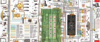
Complete information is provided about electrical equipment, wiring, relays and fuses of VAZ-2170 - VAZ-21728 vehicles. The collection is intended for auto electricians and those who, having some knowledge of circuit design, can carry out minor auto repairs with their own hands. The Lada Priora sedan (VAZ-2170) has been produced since 2007, the VAZ-2172 hatchback since 2008, and the VAZ-2171 station wagon has been produced since 2009. In 2013, the car was modernized and they began installing an AMT robotic gearbox (21723, 21728).
There are 4 main harnesses in the Priora electrical circuit:
- from the instrument panel;
- providing motor control;
- front electrical harness;
- rear electrical harness.
All these harnesses are connected to each other using detachable connections. The connectors are located under the dashboard. Each of the harnesses is assigned a serial number.
In addition to the main ones, there are also secondary ones:
- installed in the front passenger door;
- identical in both the left and right rear doors;
- installed in the driver's door;
- connecting the backlight of the license plate;
- connecting the electrical package.
Each element in the diagram corresponds to a number with an explanation. Since all elements are standardized, their designations are identical on car diagrams of all car manufacturers. Next to each electrical appliance, the connectors that go to them are indicated. The pins or sockets of the pads are also numbered.
Messages 7
1 Topic by Admin 2013-07-05 13:09:37
- Admin
- Administrator
- Inactive
- Registration: 2012-02-20
- Messages: 3,257 Thanks : 624
Topic: Is it possible to connect the light control module from Priora to a VAZ 2110?
Ideally, I would like to get a working connection diagram for this module instead of the standard “decimal” ones that are on the instrument mask.
2 Reply from Serg 2013-11-02 14:17:26
- Serg
- Lada2111.rf fan
- Inactive
- Registration: 2013-07-29
- Messages: 830 Thanks : 363
- Car: 2111 dwg 2114 year 2008
Re: Is it possible to connect a light control module from Priora to a VAZ 2110?
Connecting a light control module from Priora
We have a module with one 12-pin connector (No., color in prior) wire purpose (function) 1 - orange-black - input indicating that the rear foglights are on 2 - orange-white - output controlling the activation of the rear + front foglights 3 - yellow - input indicating that the front ones are on prottumanok 4 - brown - output control the brightness of the backlight of the buttons 31 - black - ground (it is also mass in Africa) 30 - pink - input +12volts from the battery 56 - green - output +12volts turn on the head light 58 - whitechern - output +12volts turn on dimensions 56v - serkras - +12 volt input after turning on the head light to control the fog light 58v - white - input for the illumination of the Xz - synchern - +12 volts after the ignition switch G - blue - to control the headlight range control
56 Xz 31 58b 56b G 30 58 4 3 2 1
After comparison with the 2110-2112 scheme, the following came out:
1) it is possible to connect this unit without an electrical package control unit Priors without foglight controls (I will finalize it later) all other wires somehow match in color (.) must be connected to the connector (standard 2110) light control except for the following wires: 1 – orange-black, 2 – orange white, 3 – yellow, 4 – brown (use standard regulator 2110), G – blue (if you want to connect the headlight range control, knock on the priors)
2) it is possible to install a control unit for the Priora electrical package (but later)
3 Reply from Admin 2013-11-13 13:45:45
- Admin
- Administrator
- Inactive
- Registration: 2012-02-20
- Messages: 3,257 Thanks : 624
Re: Is it possible to connect a light control module from Priora to a VAZ 2110?
That is, here are the contacts of the ICC Priora that should be used? 31- black - ground (it is also mass in Africa) 30- pink - input +12 volts from the battery 56- green - output +12 volts turns on the head light 58- belchern - output +12 volts turns on the headlights 56v-serkras - input +12 volts after turning on the headlight light for control fog 58V - white - input to the Xz block illumination - synchern - +12 volts after the ignition switch
Here is the standard switch for the low beam and dimensions of the old-style instrument panel (on diagram No. 36)
30 (pink) - connect to 56 (green) 58 (white-black) - connect to 31 (black) 56 (green) - connect to 58 (belchern) X (blue-red) - this is also a mass.
I found the remaining contacts in the VAZ 2110 mounting block: Ш3-4 (+12V) - connect to 30 (pink) Ш3-1 or Ш3-3 - connect to 56V (serkras) Ш2-8 - connect to 58V (white) Ш1-4 and Ш4-17 - connect to Xz (synchern) Is that right?
I looked at the contacts from the mounting block here
4 Reply from Serg 2013-11-13 16:20:04 (2013-11-13 16:50:09 edited by Serg)
- Serg
- Lada2111.rf fan
- Inactive
- Registration: 2013-07-29
- Messages: 830 Thanks : 363
- Car: 2111 dwg 2114 year 2008
Re: Is it possible to connect a light control module from Priora to a VAZ 2110?
No, it’s not right on the standard light switch 2110 to connect all the wires in the same colors with the Priora IUS, something like this
Priora 2110-212 30 (pink) - connect to 30 (pink) 58 (white-black) - connect to 58 (belcher) 56 (green) - connect to 56 (green) X (blue-red) - X (blue-black) +12 volts after the ignition switch
The wires of the MUS Priors 1 - orange-black, 2 - orange-white, 3 - yellow, have a trigger switch (i.e. pressed once, turn on a second time, turn off) the triggers are located in the Priora's electrical package unit, so simply connecting them to 2110 will not work, you need to come up with a diagram
Imported or domestic
Imported analogues of bearings have a slightly different designation, namely:
Most 80-amp generators have bearings of similar sizes, at least this applies to domestic ones. If the generator has already been replaced before you, then you may be faced with the fact that a generator from a different manufacturer is installed and the bearings are of different sizes. Depending on the generator manufacturer, bearings of other sizes are sometimes found, for example, in the fairly common Bosch 14V 53-98A 0124 415 038 generator, bearings 6003-2RS (rear) are installed, the dimensions of which are 17 × 35 × 10 and 6303-2RS (front) , respectively, 15×35×14. The same bearings can be found in other imported generators. However, there are options where the rear bearing is designated as 6000-2RS, and the front bearing – 6203-2RS.
In order to accurately determine the dimensions of the bearing, it will have to be removed. If the markings on the bearing are not visible, then it is best to turn to professionals (you should not trust a caliper).
If you have decided on the size of the bearing, then to the repeated question “What bearings are on the VAZ-2110?” The answer suggests itself - original!
The quality of bearings varies from manufacturer to manufacturer; some prefer to install bearings from domestic manufacturers on their generators, while others prefer imported ones. When repairing a generator, everyone decides this issue for themselves, but after listening to numerous tips, some car enthusiasts are inclined to choose imported ones. If you focus on price-quality ratio, many experts recommend DAS LAGER Germany. But there are other suppliers of quality bearings: the French company SNR; FAG is one of the leading companies in Germany; NSK is another major bearing manufacturer from Japan; NTN – Japan; Kouo - part of the Toyota concern of Japan; Kraft or BOSCH.
We also supply bearings from Chinese manufacturers, but the attitude of motorists towards generators and bearings from the Middle Kingdom is far from flattering. A bearing is considered original if it is approved by the vehicle manufacturer for sale on the market. It usually corresponds to what is (or was previously) supplied to the assembly line. The car manufacturer guarantees that these bearings will not let you down.
If you are considering various options, then all the bearings with the corresponding markings at first glance look the same, but after opening the package, you need to pay attention to the marking, which, in addition to the designation of the bearing itself, consisting of digital and letter designations, must contain an indication of the manufacturer and necessarily the country of origin. If this is not the case, then it is quite possible that it is a fake. In this case, the money lost will not be that big (most often up to 100 rubles per bearing)
But you will lose significant time and nerves
In this case, the money lost will not be that big (most often up to 100 rubles per bearing). But you will lose significant time and nerves.
Electrical circuit diagram of the lighting control module of the VAZ 2170 (Priora).
Electrical circuit diagram of the lighting control module of the VAZ 2170 (Priora).
Module diagram.
Module pinout.
Contact
| Purpose | |
| 1 | Indicator signal for turning on the rear fog lights |
| 2 | To the rear fog lamp relay |
| 30 | + 12 V (battery terminal 30) |
| 31 | Frame |
| 56 | To the headlights |
| 58 | To side lights |
| 58b | To sources of illumination of controls and instruments |
| G | To gear motors for headlight range control |
| Xz | + 12 V (terminal 15) |
| 3 | Warning signal for turning on fog lights |
| 4 | To the fog light relay |
| 56b | To the automatic headlight control system controller |
1 Symbols and index - white with light green backlight. 2 The position of the key or wheel is not fixed. 3 The color of the control indicators when not illuminated is uniform gray, turning to black; in the illuminated state: – yellow, for the rear fog lamp switch; – green for the front fog lamp switch. 4 Symbols on the electrical diagram: A1 – instrument lighting regulator; A2 – headlight range control switch; A3 – external lighting switch; A4 – front fog lamp switch; A5 – rear fog lamp switch; ХL1_ ХLn – LEDs for illuminating symbols (symbols); XL2 – LED illumination of the indicator of the outdoor lighting switch; XL3 – LED illumination of the control indicator for turning on the rear fog lights; XL4 – LED illumination of the indicator light for turning on the front fog lights.
Repair of the ICC
To repair the light control unit, you only need a little skill in using a soldering iron, the soldering iron itself and solder.
To repair the light unit, it must be dismantled.
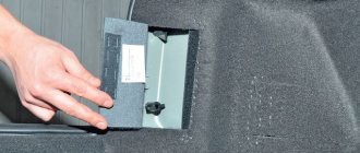
Remove the fuse box cover by turning the three fasteners 90°.
We unscrew the screw securing the MUS, take it out and disconnect it from the chip.
Disassembling the module
Pull the switch up and remove it, then use a screwdriver to pry up the bottom of the switch and remove it.
Carefully bend the 4 plastic clips, be careful the plastic is not elastic and breaks easily.
We remove the front cover of the MUS and take out the board by pressing on the contacts from the back side, the board will rise. Do not use too much force to avoid damaging the board!
The light control unit is disassembled and you can start soldering. The photo shows the places that are most subject to load and are the culprits in the malfunction of the module; they need to be soldered.
After the contacts are soldered, it is recommended to clean the contact stain with a file or sandpaper.
After the repair, we assemble the module in the reverse order and install it in place.
As you can see, there is nothing complicated in repairing the light control unit.
Source
Schematic diagram (pinout) of connecting the front wiring harness on the Priora
The front part of the vehicle's electrical circuit is designed to supply voltage to the primary and auxiliary power circuits of the vehicle's on-board systems. The decoding of contact group chips is as follows:
- 1 – starter power supply;
- 2 – battery;
- 3 – charge supply from the generator;
- 4 – connecting block for the bundle (1 – 3);
- 5-7 – power supply to the device;
- 8 – engine compartment lighting lamp;
- 9-10 – head light;
- 11 – brake expansion tank level indicator;
- 12 – outside temperature;
- 13 – washer drive;
- 14 – external indication of reverse gear;
- 15 – cooling system fan;
- 16 – stove reducer;
- 17 – reserve resistor;
- 18 – wiper drive;
- 19 – interior relay and fuse module;
- 20 – stove motor;
- 21 – sound alarm indicator;
- 22 – horn power supply;
- A1/2, B1/2 – mass.
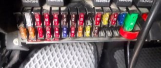
Location of Priora fuses under the hood
- F1 (30 A) – power supply fuse for the electronic engine control system (ECM);
- F2 (60 A) – fuse for the power supply circuit of the engine cooling system fan (power circuit), additional relay (ignition relay), rear window heating, electrical package controller;
- F3 (60 A) – fuse for the power supply circuit of the electric fan of the engine cooling system (relay control circuit), sound signal, alarm signal, ignition switch, instrument cluster, interior lighting, brake light, cigarette lighter;
- F4, F6 (60 A) – generator power circuit fuses;
- F5 (50 A) – fuse for the power supply circuit of the electromechanical power steering
Relay and fuse box for Halla air conditioner
- right electric fan power supply fuse (30 A);
- fuse for the power supply circuit of the left electric fan (30 A).
- right electric fan relay;
- additional relay (sequential activation of left and right electric fans);
- left electric fan relay;
- heater fan power supply fuse (40 A);
- compressor power supply fuse (15 A);
- heater fan relay;
- compressor relay.
Panasonic air conditioner relay and fuse box
- Heater fan maximum speed
- Right fan
- Fan sequential relay (low speed)
- Left fan
- Left fan fuse (low speed)
- Right fan
- Heater fan
- Compressor
- Heater fan
- Compressor
VAZ 2170 ECM harness connection diagram
This part is organized to supply power to the main instruments and engine control system of the Lada Priora. From here, voltage is supplied to the main components, units of the vehicle’s power plant, as well as control sensors and ECUs. The standard electrical circuit connection system (pinout) looks like this:
- 1 – ECU power supply;
- 2 – main block of the electronic system to the dashboard;
- 3 – distribution board;
- 4 – speedometer;
- 5 – road surface roughness sensor;
- 6 – indication of pressure in the engine crankcase;
- 7 – TPS;
- 8 – DTOZH;
- 9 – indication of antifreeze temperature sensor;
- 10 – mass air flow sensor;
- 11 – control XX;
- 12 – main relay of the fuel pump;
- 13 – VT circuit fuse;
- 14 – relay BZ;
- 15 – fuse of the above circuit;
- 16 – ECU fusible link;
- 17 – DPKV;
- 18 – power supply for mass air flow sensor;
- 19 – phase distribution;
- 20 – mixture detonation sensor;
- 21 – EMC for purging the adsorber;
- 22 – diagnostics of the air flow sensor;
- 23 – power supply to the ignition coil;
- 24 – supply voltage to spark plugs;
- 25 – power supply to fuel injectors;
- 26 – terminal from the ignition coils to the ECM;
- 27 – feedback from 26;
- 28 – ECM connector to the injection system;
- 29 – response to the previous output;
- A – phase on the battery;
- B1/2 – ignition mass;
- C1 – mass from short circuit.
Electrical circuit operation
It runs on a gasoline engine with electronic ignition, and the power system of the Lada Priora is injection. Correct fuel supply is carried out thanks to an electrical controller, and the mixture is ignited using a regular spark. All other components of the Priora are not paramount, since they are designed to provide factors such as safety and comfort while driving. In general, the VAZ scheme is divided into 2 categories:
The electrical wiring diagram is based on detachable connections, due to which, in a fairly short period of time, not only diagnostics of any Priora breakdowns is carried out, but also troubleshooting.
Interpretation of the symbols for the rear wiring harness of the VAZ Priora
The rear part of the electrical wiring chain is responsible for the vehicle's lighting and peripheral systems. This includes lights, locks and windows. The pinout of tips and terminals looks like this:
- 1 – dashboard response;
- 2 – power supply for the door behind the driver;
- 3/28 – power supply for the front passenger panel equipment;
- 4 – maintenance of power windows and door locks;
- 5-6 turn signals;
- 7 – interior lighting;
- 8 – handbrake indication switch;
- 9-10 – aft dimensions;
- 11 – temperature inside the car;
- 12-15 – circuit breakers for lighting the interior of the machine;
- 16/17 – power supply to the devices of the aft right and front left doors, respectively;
- 18/19 – voltage to the rear right and left speakers, respectively;
- 20 – cigarette lighter power core;
- 21 – EBN;
- 22 – contact group of the cargo compartment lighting circuit breaker;
- 23 – heated rear windshield;
- 24 – luggage compartment lighting lamp;
- 25 – additional stop;
- 26 – power line to the electric lock of the luggage compartment lid;
- 27 – power supply for rear number plate illumination;
- A1-4 – mass;
- ХР1/3 – electrical package power controller.
Pinout for rear license plate illumination of VAZ 2170
The small harness, located in the luggage compartment, has only three terminals:
- 1 – power supply to the stern license plate lights;
- 2-3 – license plate lighting lamps;
- 4 – trunk lid lock motor.
Pinout for the driver's door of the Priora
The harness is routed to supply power to the driver's door equipment. There is an output to the key panel installed in the armrest. There are six elements in total:
- 1 – additional terminal to the rear of the machine;
- 2 – line to the left fuse;
- 3 – electric window drive;
- 4 – armrest control module;
- 5 – door lock drive;
- 6 – rear view mirror control chip.
Additional brake light
The additional brake light uses LEDs instead of lamps. If the LEDs are faulty, the lamp assembly must be replaced. The work is shown on a hatchback car. On a sedan car, the light is secured to the rear window shelf from below with two screws from the luggage compartment.
Installing an additional brake light may require two new headliner brackets.
1. We prepare the car for work.
2. Having opened the tailgate, use a slotted screwdriver with a thin blade to remove two plugs from the housing of the additional brake light.
In addition to the flashlight wires, a rear window washer tube is routed through the corrugated hose. As a result, it is difficult to pull out the wires, much less re-stretch them together with the block.
6. Mark the colors of the wires on the block and use an awl or a screwdriver with a thin blade to release the wire retainer.
7. Remove the wire clamp from the block.
8. Use a needle or the end of a metal clip to tighten the tip lock and remove the wire tip from the block.
9. Similarly, remove the tip of the second wire from the block.
10. Remove the rubber seal from the door opening.
11. Pull the flashlight wires out of the corrugated hose.
12. Pull the wires out of the door hole.
13. Using an 8 mm socket wrench, unscrew the two nuts securing the additional brake light.
14. Remove the additional brake signal light from the car.
Install the additional brake signal light in the reverse order.
Warning!
We connect the wires to the block taking into account their color. You can check the correctness of the connection by focusing on the block of wires under the upholstery: the wires should be connected to the connector so that the red wire is located opposite the red one, and the black wire is opposite the black one.
Electrical diagram of the dashboard (Torpedo) VAZ-2170 Priora
Part of the on-board network is designed to power the main group of vehicle equipment. The control and display elements of the instrument panel are concentrated here. The wiring supplies power to loaded parts and critical components:
- 1-3 – contact group of the front harness;
- 4 – supply voltage to the aft connector;
- 5 – power supply from the fuse panel;
- 6 – contact group of stops;
- 7 – instrument panel indication;
- 8 – control of illuminators;
- 9 – contact group of emergency airbags;
- 10 – horn;
- 11 – power supply of the diagnostic unit;
- 12 – on-board PC control;
- 13 – ignition coil controller;
- 14 and 15 – supply voltage to the EUR control unit;
- 16 – control of power window equipment;
- 17 – alarm relay;
- 18 – wiper regulator;
- 19 – air flow distributor for the ventilation system;
- 20 – stove;
- 21 – heater drive;
- 22 – heated rear wind window;
- 23 – onboard clock;
- 24-25 – radio connection;
- 26 – emergency warning button;
- 27 – glove compartment lighting;
- 28 – control button for the glove box illumination;
- 29 – bundle of wiring for ignition;
- 30 – to the emergency airbag control board.
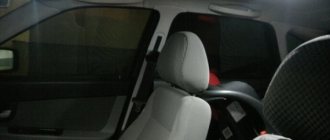
Opel Astra TURBO RESTYLING › Logbook › Replacement of interior lighting lamps!
Hello to all readers of my logbook!))) It’s immediately clear that the yellow light in the car is nothing... I decided to replace the standard lamps with LEDs! They were replaced a long time ago, but I just couldn’t get it together, choose the time and create a BZ...))) I bought 5 baseless LEDs for the lampshades, 4 LEDs for illuminating the sun visors
Then I took the lights apart. Disassembling the lights is simple, all fastenings are snapped, carefully pry and remove...
I didn’t install a central LED, because I don’t need light when opening the door, and in the future the lights for the legs and doors will be connected to this connector, but more on that in the next blog…)))
Then we put everything together and here is the result:
The central section does not light up, only the outer sections light up. There is plenty of light...
Then we move on to the rear courtesy lamp. Everything is sorted out and changed in exactly the same way...
Then we move on to illuminating the glove compartment. The yellow light in it doesn’t inspire me either... So I took out the flashlight, pulled out the old lamp and inserted a new diode... To pull out the flashlight you need to pry it off with a flat screwdriver, as if from the inside...
The only thing left to do is to replace the lamps in the sun visors... As with all lampshades, it is extremely simple... The glass is removed, the lamp is taken out and the diode is installed... But there were some problems, the diodes were larger than the original lamps, so they had to be filed a little))) Unfortunately there are no photos of the finalization...
I immediately thought that the diodes would produce less light, but it turned out to be the opposite... Overall, I’m very pleased with the result, white light is much nicer!))) Don’t forget to comment and like!))) If you like it, of course!))) Thank you all for your attention! )))
Price: 500 ₽ Mileage: 1000 km
Pinout of the instrument panel VAZ 2170 Priora
The layout of the instrument panel is made in a simplified version to facilitate the replacement and installation of replacement parts. The decoding of the wiring connections at the factory terminals looks like this:
- 1 – EUR;
- 2 – emergency signal control;
- 3 – oil pressure sensor;
- 4 – indicator light for turning on the hand brake;
- 5 – immobilizer control unit;
- 6 – control unit for airbags;
- 7 – external lighting of the car;
- 8-9 – direction indicators;
- 10 – control of the combustible mixture injection system;
- 11 – disabling the front passenger SB;
- 12 – indication of seat belt buckles;
- 13 – operation of the brake system;
- 14 – reset button of the steering column switch;
- 15 – indication of the expansion tank of the brake system;
- 16 – ABS control unit;
- 17 – headlight high beam position switch;
- 18 – dashboard lighting;
- 19 – mass;
- 20 – receiving power from the battery terminal;
- 21 – ignition switch connector;
- 22 – fuel consumption sensor;
- 23-24 – BC mode switch;
- 25-26 – temperature sensor “overboard”;
- 27 – remaining fuel in the tank;
- 28 – speedometer;
- 29 – antifreeze temperature indication;
- 30 – tachometer;
- 31 – diagnostic terminal;
- 32 – power supply from generator (L).
Tuning and replacement of the center console on Lada Priora and Kalina
Modern versions of cars are supplied to the market with a restyled version of the tidy. Here, a relatively old generation, navigation and a liquid crystal display appeared. Installing an updated shield requires the following steps.
Selecting the required version
There are only two types of updated designs with and without a CAN bus. The nuance is that the versions are completely identical in appearance. In order to find out which variety is suitable, you need to check the production date of the car. Machines manufactured before 06, 2012 are not equipped with this technology. The article numbers for the new devices with navigation are as follows:
- 2170-3801010-50 without CAN;
- 2170-3801010-60 with CAN.
Also in the kit you need to purchase a navigation antenna and a steering column switch of the appropriate design.
Installation nuances
For Lada Kalina versions, all devices are not equipped with a CAN module. Also the old generation of Priora. Here the installation is carried out without modifications or nuances - just snap out the old panel, remove the terminals, and mount the new set on the stock fasteners. Next, you need to install a navigation antenna on the roof and connect it to the appropriate connector. The second case is when an old panel with a CAN unit, but without navigation, is replaced with an analogue one. Here it is necessary to rearrange the contact connectors of the standard wiring from positions 10-11 to sockets No. 28-29. In case of incorrect operation of the devices, the replaced wires are swapped with each other. After the repair is completed, the counters should reset to zero.
How to determine the malfunction?
If you notice that there are problems with the wiring of the Priora or one of the devices is not functioning, then you can diagnose the voltage using a multimeter. In particular, you will need to check whether there is voltage in the power circuit connecting the failed device to other devices.
How to do it correctly:
- First you need to switch the tester to voltmeter mode.
- Next, one tester probe is connected to the battery or vehicle body, depending on where the device being diagnosed is located.
- The second probe of the device must be connected to the supply cable in the circuit being diagnosed, but before this the terminals from the device must be removed.
- If, during diagnostics, readings appear on the tester screen, this indicates that there is voltage in the circuit, and accordingly, the tested wires are in good condition.
- Similar actions are performed with the remaining wires that require checking. If you eventually find a point where there is no voltage, then this indicates that the source of the breakdown is located in this section of the circuit. The only thing left to do is to simply find the cause and get rid of it (the author of the video is the PRO.Garage channel).
If there is no voltage in the circuit at all, you can diagnose a possible short circuit.
To do this, follow these steps:
- First, you need to remove the part that is responsible for the circuit being diagnosed from the fuse block.
- As in the previous case, the multimeter should be activated in voltmeter mode.
- One tester probe should be connected to the safety element connection outputs. Make sure that all other equipment and devices in this circuit are not connected.
- Then move the wire itself a little - if at this moment indicators appear on the display, this indicates that the wire has a short somewhere. The problem must be solved as quickly as possible - qualified electricians say that in principle it is not worth bringing the electrical circuit to such a state.
Read more: Honda SRV or Hyundai Tussan
A short circuit usually appears in that section of the circuit where the insulation has worn off. This procedure can be carried out with any component of the electrical circuit, as well as with switches. If the diagnostics showed the absence of a short circuit, then there is another test option.
In particular, we are talking about searching for a possible break in the electrical network, the procedure is performed as follows:
- First you need to turn off the power to the on-board network or just one area that you want to check. To do this, either disconnect the terminals from the battery, or simply remove the safety device from its mounting location.
- Now we proceed directly to the test - the tester probes should be connected to the two ends of the electrical circuit section.
- Next, one of the probes should be connected to the car body; you need mass.
- If, at the time of connection, indicators begin to appear on the tester’s display, this indicates that there are no breaks in this section of the electrical circuit. If there are no changes, then we can say with confidence that there is a break in the wiring.
Pinout of the lighting control unit on Priora
The module is connected to the vehicle’s on-board network via chip No. 1118-3724500. The standard terminal pinout on a VAZ 2170 looks like this:
- G56b – for the gearbox for adjusting head lighting devices;
- 58b – output from lighting and instruments;
- 31 – neutral earth cable;
- Xz – 12 volts from pin 15 of the ignition switch;
- 56 – relay switch for high and low headlight modes;
- 1, 3 – connection of fog lights;
- 2, 4 – sending a signal to the controller;
- 58 – dimensions;
- 30 – power supply from the ignition switch design.