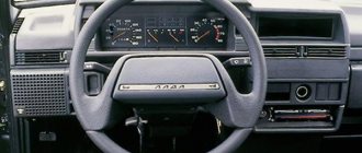
Many owners independently maintain a good and reliable VAZ 21099 car and try to improve it in every possible way. This is especially true when replacing the instrument panel with a “high” one, since many people like its design. It is possible to do this yourself, it is only important to have the electrical diagram of the car at hand.
Is it difficult?
But not only the diagram, but also to convert the carburetor VAZ 21099 you will need:
- Interior wiring for the Euro panel;
- Fuse box from model 2114 (contains 9 fuses);
- Directly the “euro” panel itself;
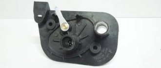
- New speed sensor with wires;
- New ignition switch.
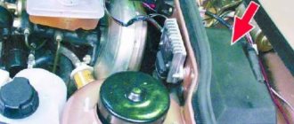
Fuse box model 2114-3722010-60
For reference: the VAZ 21099 wiring for the carburetor differs from the wiring for the Euro panel in the presence of additional sensors and a different arrangement of indicators of their operation.
Read also about the differences between modifications of the VAZ 21074 electrical wiring.
Modifications of VAZ-2109
VAZ-2109 . The basic model, which was produced from 1987 to 1997, was equipped with a 1.3-liter VAZ-2108 carburetor engine with a capacity of 64 horsepower.
VAZ-21091 . Modification of a car with a derated VAZ-21081 engine, 1.1 liter and 54 horsepower. It was mass-produced from 1987 to 1997.
VAZ-21093 . Modification of a car with a VAZ-21083 carburetor engine, 1.5 liters and 73.4 horsepower. Serially produced from 1988 to 2006.
VAZ-21093i . Modification with a VAZ-2111-80 injection engine, 1.5 liters. the first prototype appeared in 1994, mass production began in November 1998.
VAZ 21093-22 . Model made specifically for the Finnish market. It features improved interior trim, pre-installed alloy wheels and a new dashboard. The car was equipped with a 1.5 liter injection engine. Produced from 1995 to 1998.
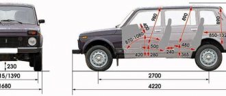
VAZ-210934 . An all-wheel drive SUV with a VAZ-21093 body mounted on a Niva frame, on which the suspension, steering, engine, gearbox and transfer case from the same VAZ-2121 Niva model were already installed.
VAZ 2109-90 . A variant of the car, which was equipped with a compact two-section Wankel rotary piston engine with a volume of 654 cm3.
VAZ-21096 . Export modification of the VAZ-2109 for countries with left-hand traffic, the steering column was located on the right.
VAZ 21097 . Export modification of VAZ 21091 with right-hand drive.
VAZ 21098 . Another export modification, but this time the VAZ 21093 model with a right-hand steering column.
VAZ-2109 Carlota . A car produced from 1991 to 1996 in Belgium by Scaldia-Volga.
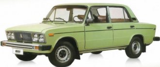
VAZ-21099 . The next independent car model, which is a modification of the “nine”. This car had a 4-door, 5-seater sedan body and a rear overhang extended by 200 mm.
Wiring diagram for VAZ-2109 carburetor
- Headlight.
- Electric motor for headlight glass cleaning system. An optional part, used mainly on export vehicles.
- Limit switch for powering the engine compartment lamp.
- Klaxon.
- An electric motor drives a fan installed on the radiator of the cooling system.
- Temperature indicator that provides a control signal for the electric drive of the fan impeller.
- Alternator.
- Fluid supply valve for headlight glasses. Used in conjunction with paragraph 2.
- Fluid supply valve for the glass of the fifth door.
- Fluid supply valve to the front glass.
- Spark plugs.
- Hall sensor used to distribute ignition pulses.
- Coil.
- Limit switch for reverse gear lights.
- Fluid temperature meter in the cooling system.
- Starter.
- Accumulator battery.
- A sensor that measures the fluid level in the brake booster.
- Switch that controls the ignition system.
- Sensor for determining the position of the top dead center of the piston of the first cylinder. Installed on some export VAZ 2109 with a diagnostic system. Found only on cars before 1995.
- Diagnostic block. Optional element, installed together with item 20.
- Controller for controlling the solenoid valve installed in the carburetor.
- Starter switch contact block.
- Limit switch on the carburetor.
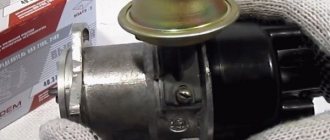
- Economizer valve.
- Sensor signaling an emergency decrease in oil pressure.
- Washer pump drive.
- Fan impeller motor for ventilation and heating systems.
- Resistance providing additional fan speeds.
- Speed shifter.
- Windshield wiper drive.
- Cigarette lighter.
- Illumination system for levers for adjusting heater operating parameters.
- Socket for additional equipment.
- Lamp for auxiliary lighting of the engine compartment.
- Illumination system for the glove box on the instrument panel.
- Relay and fuse link mounting block.
- Instrument panel light switch.
- Parking brake lamp limit switch.
- Brake lamp limit switch.
- Steering column switch lever block.
- Exterior lamp switch.
- Hazard switch.
- Turn on the rear fog lamp.
- Bimetallic fog lamp fuse.
- Heated glass switch on the fifth door.
- Turn signal repeaters on the front fenders.
- Central interior lighting.
- Individual lampshade.
- Switches for backlight operation on the middle pillars.
- Ignition switching unit.
- Egnition lock.
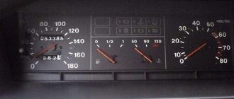
- “Low” type instrument cluster.
- Choke limit switch on the carburetor.
- Rear lights.
- Fuel level meter in the tank.
- Heated glass.
- Rear wiper drive.
- Two lamps for room illumination.
Disassembling the panel
We arm ourselves with tools and start disassembling. At first:
- Disconnect the battery;
- Remove the front panel (it is secured with latches and screws);
- We remove the instrument assembly;
- Carefully disconnect all contacts and connectors on the wires;
- Remove the plastic panel from the steering column;
- Disconnect the ignition switch and dismantle it;
- We release the wiring harnesses going into the engine compartment;
- We remove them through the technological hole.
A low panel is mounted on a shelf in the garage
Advice: do not use force - the latches on the panel are pryed off with a screwdriver. You may still need the old panel, so keep it in working order. And the growing price on the secondary market for old spare parts also contributes to this.
Equipment diagram for VAZ-2109 injector
The VAZ 2109 wiring for the injector has many connectors for connecting sensors to the computer.
- TPS (throttle position sensor);
- DPKV (crankshaft position sensor);
- DT (temperature sensor);
- DSA (vehicle speed sensor);
- Canister purge valve;
- MAF (mass air flow sensor);
- DD (knock sensor) and others.
The weak point of the harnesses is the power wiring on the bottom shelf of the radiator, which is constantly exposed to high temperatures and in this place it is in no way protected from water and dirt. Another problem is a harness under the carpet next to the driver's seat. Moisture constantly accumulates there, and in order to remove it, you need to dry the floor, inevitably tugging on the rope.
Since the mid-90s, VAZ 2109 began to use engines with an injection system, which greatly changed the electrical layout of the engine compartment and instrument panel. Below is an electrical diagram of a 1999 car with an ECM type GM ISFI-2S and January 4/4.1.
- 1 - nozzle system;
- 2 - candles;
- 3 — ignition control module;
- 4 — diagnostic connector;
- 5 — General Motors or January controller;
- 6 — connector for connecting the instrument cluster;
- 7 — main relay of the system;
- 8 — fuse for power supply wiring of the controller and ignition system module;
- 9 — protection of the speed sensor and air flow meter circuits;
- 10 — fuel supply pump power protection;
- 11 — fuel pump controller;
- 12 — engine temperature meter;
- 13 — idle system;
- 14 — detonation meter;
- 15 — tank purge system for collecting fuel vapors;
- 16 — crankshaft position meter;
- 17 — speed meter;
- 18 — air flow meter;
- 19 — lambda probe;
- 20 — throttle position angle meter;
- 21 — electric fuel pump complete with fuel level sensor;
- 22 — connection of the ignition system;
- 23 — control lamp;
- 24 — ignition switch;
- 25 - switching block;
- 26 — radiator cooling fan.
Since 2002, all VAZ 2109 began to be equipped only with engines with an injection system. The diagram shows the electrical wiring harness for the Bosch MP7.0 ECM (Euro 2 standards) on a 2003 car with a VAZ 2111 engine.
- 1 — four nozzles;
- 2 — spark plugs 2109;
- 3 — ignition distribution module;
- 4 - diagnostic connector, led into the car interior;
- 5 — Bosch controller connector;
- 6 — connector for the combination of lamps and instruments;
- 7 - main switching device of the system;
- 8 — fuse-link of the main device;
- 9 — controller for controlling the parameters of the fan on the cooling radiator;
- 10 — fan controller fuse;
- 11 — fuel pump control relay;
- 12 — fuel pump wiring fuse;
- 13 — intake air flow sensor;
- 14 — throttle opening angle sensor;
- 15 — engine temperature meter;
- 16 — regulator of idle speed parameters;
- 17 — sensor for measuring detonation in cylinders;
- 18 — crankshaft position sensor;
- 19 — lambda probe;
- 20 — immobilizer control unit;
- 21 — immobilizer status indicator;
- 22 — speed sensor;
- 23 - electric motor for driving the fuel pump; in the same module there is a device for measuring the remaining fuel in the tank;
- 24 — purge valve for the gasoline vapor recovery system;
- 25 — connector of the ignition system braid;
- 26 — instrument cluster with Check Engine indicator and warning lamp;
- 27 — ignition system start relay;
- 28 - lock;
- 29 — installation and switching block;
- 30 - cooling system fan.
Relay and fuse box diagram 2109
The fuse blocks do not depend on the fuel injection system used - carburetor or injector. BP will differ only by year of manufacture of the car. That is, the mounting blocks for the carburetor and injector are the same. The VAZ 2109-099 fuse box (carburetor, injector) is located under the hood, in the compartment in front of the windshield on the left side.
Fuse block 2114-3722010-18
K1-relay for turning on headlight cleaners; K2-relay-breaker for direction indicators and hazard warning lights; K3 - windshield wiper relay; K4-relay for monitoring the health of lamps; K5-power window relay; K6 - relay for turning on sound signals; K7-relay for turning on the electric heating of the rear window; K8-relay for high beam headlights; K9-relay for low beam headlights; F1-F16 - fuses.
Fuse block 2114-3722010-60
K1 - Headlight wiper relay, K2 - Turn signal and hazard warning relay, K3 - Windshield wiper relay, K4 - Brake light and parking light relay, K5 - Power window relay, K6 - Horn relay , K7 - Rear window heating relay, K8 - Headlight high beam relay, K9 - Headlight low beam relay, F1 - F16 - Fuses, F1 - F20 - Spare fuses.
Attention! The power terminals on the generator often become loose, heat up, spark and melt the wiring. Pay attention to this point when searching for possible faults yourself.
The weak link in the electrical equipment of Lada
In a VAZ car, such repairs or replacement of the device are carried out as follows. All terminals are unscrewed and wires are removed. The nut that regulates the tension of the generator belt is loosened. Then the device moves away and the belt is removed. After unscrewing the bracket and the adjusting bar, the faulty generator is removed. A new device is installed in its place. Installation of a new generator is carried out in reverse order.
To avoid problems with recharging the battery in the future, this procedure should be repeated after the next ten thousand kilometers.