The stability of the engine is directly related to the condition of the air filter. It is entrusted with the function of preventing abrasive particles from entering the combustion chamber.
During operation, dust and dirt gradually accumulate, causing the filter to become clogged. This leads to a decrease in the dynamic performance of the VAZ 2109, and also causes an increase in gasoline consumption. If the pollution is severe, the speed starts to fluctuate and the engine “chokes.”
Air filter for cars with a carburetor
The air filter for the VAZ 2109 differs depending on the engine and year of manufacture of the vehicle. If a carburetor is installed on the car, then the original consumable has article number 21010110910002. The price for it is 120-235 rubles.
On later VAZ 2109 cars, an injector is used. The air filter on such machines is completely different in design. Consumables are not interchangeable. The original air filter for the injection VAZ 2109 comes with catalog number 2112-1109080. Its cost ranges from 220 to 300 rubles.
Original air filter for injection VAZ 2109
Third-party manufacturers also produce filters for the VAZ 2109. Many analogues have a very attractive price-quality ratio. The tables below show recommended consumables that perform well on cars.
Table - Analogues of the original air filter 21010110910002
| Brands of analogues of the original air filter | Catalog number | Cost, ruble |
| Starline | SFVF2189 | 120-150 |
| Mfilter | A101 | 60-90 |
| WIX | WA6395 | 140-160 |
| Starline | SFVF2189 | 150-180 |
| Bosch | 1457432108 | 440-500 |
Table - Alternatives to branded air filter 2112-1109080
| Manufacturer | Article number | Price, ruble |
| VAG | 021129620D | 500-620 |
| Starline | SFVF2246 | 140-200 |
| Febi | 1510 | 300-350 |
| Japan Cars | B2W004PR | 100-160 |
| Filtron | AP006 | 220-250 |
Engine power system
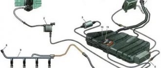
The power system includes the following devices: fuel tank 40, gasoline vapor separator 46, fine fuel filter 33, fuel pump 32, check valve 30, two-way check valve 45, fuel lines and hoses, air filter 28 with thermostat, carburetor 29, intake pipe and exhaust gas devices.
Fuel supply with reverse drainage of part of the fuel from the carburetor back to the fuel tank through a calibrated hole in the carburetor pipe with a diameter of 0.70 mm. A check valve 30 installed on the drain hoses prevents fuel from draining from the tank through the carburetor when the car rolls over. The fuel tank is connected by a hose 43 to a separator 46, which serves to condense gasoline vapors. To prevent fuel from leaking out of the tank through the separator, a double-acting check valve is installed on the second separator hose 44. The valve works in both directions: as fuel is consumed, it allows atmospheric air into the tank, and when the pressure in the tank increases, it releases air with fuel vapor from the fuel tank.
Air is supplied through a thermostat, air filter 28, carburetor 29, from which it enters the engine cylinders in the form of a combustible mixture through the inlet pipe.
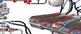
The fuel tank 40 is stamped and welded from two steel sheets. To increase corrosion resistance, the tank is leaded on both sides. Tank capacity 43 liters, including fuel reserve.
The filler neck is located in a niche in the right rear fender. The plug has a torque limiter; on some cars, a lock can be installed in the plug.
Two drain tubes 38 are installed in the fuel tank, which are inserted into one another and have a common outlet into a pipe connected to a gasoline vapor separator 46. Separator capacity 7 l. Gasoline vapors, condensing in the separator, are drained back into the tank. The ends of the drainage pipes in the tank are located on the right and left sides, respectively, in order to prevent fuel from leaking out when the car turns.
Fuel pump 32 is a diaphragm type with a mechanical drive and is equipped with a manual fuel pumping lever Capacity 60 l/min. It is driven by pusher 16 from the eccentric 17 of the camshaft. A heat-insulating spacer 15 and adjusting shims 13 and 14 are installed between the pump and the drive housing.
The fuel pump consists of a lower housing 26 with drive levers, an upper housing 20 with valves and pipes, a diaphragm assembly and a cover 21. Three diaphragms 6 and 7 are installed between housings 20 and 26: the upper two are working for supplying fuel, the lower is safety to prevent fuel entering the drive housing if the working diaphragms are damaged. Between the working and safety diaphragms there are external 27 and internal 24 spacers. The outer gasket has a hole to allow fuel to escape if the upper working diaphragms are damaged. Diaphragms 6 and 7 with plates are installed on rod 9 and secured on top with a nut. There is a compressed spring on the rod under the diaphragm assembly. The rod is inserted with a T-shaped shank into the slot of the balancer 11. The slot allows you to remove the diaphragm assembly without disassembling it.
In the lower housing 26, levers 12, 8 and a balancer 11 are installed. In the upper housing there are suction valves 3 and discharge valves 2. Gaskets made of diaphragm material are placed under the valves. The valves are pressed against the seats by springs. A cover 21 is attached to the upper housing of the pump with a central bolt. A plastic strainer 4 is installed between the housing and the cover. The upper housing 20 has a discharge 1 and suction 5 branch pipes.
Fuel is supplied by the manual pumping lever 8 by the action of the cam 10 on the balancer 11 and the fuel pump diaphragm. If the lever 8 is idling, when the carburetor float chamber is filled with fuel, it is necessary to turn the engine crankshaft one turn so that the eccentric 17 releases the pusher 16 and the balancer 11. The crankshaft is turned with a wrench clockwise using the bolt at the end of the shaft.
To correctly install the fuel pump on the engine, adjusting shims 13 and 14 are used, installed between the pump and the heat-insulating spacer, between the drive housing and the spacer (see fuel pump installation diagram). Two of the three gaskets below are used: gasket A - 0.27-0.33 mm thick; gasket B - thickness 0.70-0.80 mm; gasket C - thickness 1.10-1.30 mm.
There must always be a gasket A between the drive housing and the thermal insulation spacer
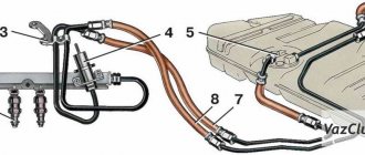
Fuel lines and fine fuel filter
Fuel lines 35 and 36 are made of leaded or galvanized steel tubes. The tubes are connected to the fuel pump and to the tank by rubber hoses in a fabric braid and secured with screw clamps. The fuel pump is connected to the carburetor by a rubber hose.
The fuel supply line 35 is made with a diameter of 8 mm, the drain line 36 with a diameter of 6 mm. In front of the fuel pump 32, a fine fuel filter 33 is installed on the hoses and secured to the hoses with screw clamps. The filter has a non-separable design with a paper filter element in a plastic housing. The plastic body and lid are welded using ultrasonic welding or high-frequency currents.
Source
Power supply system for VAZ-2108, -21081, -21083 engines
Carburetor engine power system
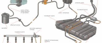
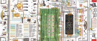
1 — fine fuel filter; 2 – fuel supply hose to the fuel pump; 3 – fuel pump; 4 – heated air intake; 5 – check valve; 6 – fuel drain hose from the carburetor; 7 – cold air intake; 8 – thermostat; 9 – air filter assembly; 10 – carburetor; 11 – fuel drain pipe; 12 – fuel supply pipe from the tank; 13 – fuel tank; 14 – flange of the fuel level sensor and fuel intake tube; 15 – separator hose; 16 – filling pipe hose; 17 – filling pipe; 18 – fuel tank plug; 19 – separator; 20 – two-way valve hose; 21 – two-way valve
Description of design
The fuel supply is located in the tank located under the bottom in the rear seat area. The tank is made of steel and consists of two stamped parts welded together. The tank is connected through a drain hose to a separator that captures gasoline vapors. The condensate from the separator is drained back into the tank. The separator communicates with the atmosphere through a two-way valve that prevents excessive increase or decrease in pressure in the fuel tank. The filler neck is connected to the tank with a gas-resistant rubber hose secured with clamps. The plug is sealed.
Through a fuel intake with a mesh filter, gasoline is supplied from the tank through steel fuel lines and rubber gas-resistant hoses to a fine fuel filter, a fuel pump and then to the carburetor. Gasoline is sucked from the tank due to the vacuum created by the gasoline pump.
Fine filter - with a paper filter element in a plastic housing, non-separable design. There is an arrow on the filter housing that must coincide with the direction of fuel movement.
The fuel pump is a diaphragm type, mechanically driven by the camshaft eccentric, with a manual pumping lever. It consists of a lower housing with drive levers, an upper housing with valves and pipes, a diaphragm assembly and a cover. The diaphragm assembly is installed between the upper and lower housings. Two diaphragms (working) are installed on top, and one (safety) on the bottom: it prevents gasoline from entering the engine crankcase when the working diaphragms rupture. In this case, leaked gasoline is discharged through holes in the external spacer located between the safety and working diaphragms.
The diaphragms, together with the internal spacer and plates (from the outside), are assembled on the rod and secured with a nut. The rod is inserted into the cavity of the balancer using a T-shaped shank. A spring is installed between the diaphragm assembly and the lower housing. The upper housing is closed with a lid secured with a bolt. Underneath there is a mesh fuel filter.
The pump is attached to the engine with two studs through a heat-insulating spacer, sealed on both sides with cardboard gaskets.
Part of the gasoline supplied to the carburetor is drained back into the tank through a system of pipelines and hoses - this improves pump cooling and prevents the formation of vapor locks in the power system. The drain line has a check valve that allows fuel to flow in only one direction - from the carburetor to the tank.
The air filter housing can receive cold air through an intake near the radiator or hot air from an intake mounted on the exhaust manifold. The flow is switched by a damper controlled by a thermostat. The built-in thermal power element opens the hot air damper when the incoming air temperature is below 25 °C and completely closes it if the air is heated above 35 °C. Thus, the temperature of the incoming air is automatically maintained within 25–35 °C.
The air filter is dry, with a replaceable paper filter element. The filter housing is mounted on the carburetor studs through a rubber gasket and secured with four self-locking nuts through a metal plate.
Source
Check and replacement
If the thermostat fails, it should be replaced immediately. It is impossible to say that the device has failed only on the basis of an initial check.
If the engine overheats during operation or does not warm up to operating temperatures quickly enough, the condition of the unit is checked. Based on the results obtained, replacement or repair is carried out.
The most effective way to check the thermostat is to remove it. The procedure is performed as follows:
- Unscrew the crankcase protection mounting bolts, after which the protection must be removed and placed aside for a while.
- Remove the cap from the expansion tank where the coolant is located.
- Place a clean container under the drain hole (if you plan to pour the same coolant back into the system), unscrew the drain plug from the cylinder block and remove all coolant from the cylinder block.
- Place a container under the drain hole of the cooling radiator, unscrew the plug and drain the antifreeze or antifreeze.
- Loosen the clamps holding the hoses.
- Disconnect the three hoses that are connected to your thermostat housing.
- Loosen the tension on the clamps and remove the thermostat along with the hose. The short hose is disconnected from the thermostat.
- Place the dismantled device in a container of water, which must be preheated to 78-80 degrees Celsius.
- Start heating the water, stirring the liquid occasionally. The water needs to be heated to approximately 87 degrees Celsius.
- If the thermostat is working properly, when the temperature reaches 87 degrees with an error of plus or minus 2 degrees, the main valve should open. If this does not happen, the device is faulty and requires replacement.
To replace the thermostat, it is enough to remove the old one in accordance with the specified dismantling instructions, and reassemble the unit with an already working device in the reverse order.
What to choose?
Many owners of a VAZ 2109 with a carburetor complain that the factory thermostat is insufficiently efficient. Because of this, especially in winter, you have to suffer from slow heating, when it is difficult to achieve even 60 degrees.
To solve this problem, it is recommended to install a thermostat from an injection VAZ 2110 with 8 valves for the winter and for the entire period of operation of the nine. This is an improved element that has obvious advantages compared to the original thermostat for the carburetor VAZ 2109.
- You should install an injection thermostat starting from tens, taking into account the fact that we are not talking about the first versions of the VAZ 2110, but later, modernized ones.
- On 8-valve engines, dozens of thermostats have become dismountable, unlike the 16-valve VAZ 2110 and those devices that were initially installed from the factory on the VAZ 2109. This allows, in the event of a unit breakdown, to disassemble it and partially repair it without completely replacing the device.
- To repair a new thermostat, borrowed from a VAZ 2110 with an injector and 8 valves, it is often enough to disassemble the device and replace the thermoelement there.
- The new unit turned out to be 50 millimeters shorter, which allows for more free space.
- The new element has lost many of the clamps that are relevant for thermostats from the VAZ 2109.
- The component has undergone quite a serious modification, which allows it to effectively maintain a stable temperature inside the engine cooling system.
Power supply system VAZ 2109 injector diagram
Diagram of the fuel system of VAZ 2108, 2109, 21099 cars
Fuel is pumped by a mechanical fuel pump from the fuel tank through an intake with a strainer into the main fuel line. Next, it enters the carburetor, where it is mixed with air coming from the engine air filter. The carburetor prepares the fuel mixture (air/fuel) in a certain proportion necessary for the engine to operate in one mode or another.
Notes and additions
— The fuel tank of VAZ 2108, 2109, 21099 cars has a capacity of 43 liters. The gasoline used in these vehicles is AI-91, AI-95.
More articles on the fuel system
Carburetor engine power system
1 — fine fuel filter; 2 – fuel supply hose to the fuel pump; 3 – fuel pump; 4 – heated air intake; 5 – check valve; 6 – fuel drain hose from the carburetor; 7 – cold air intake; 8 – thermostat; 9 – air filter assembly; 10 – carburetor; 11 – fuel drain pipe; 12 – fuel supply pipe from the tank; 13 – fuel tank; 14 – flange of the fuel level sensor and fuel intake tube; 15 – separator hose; 16 – filling pipe hose; 17 – filling pipe; 18 – fuel tank plug; 19 – separator; 20 – two-way valve hose; 21 – two-way valve
Replacement frequency
Replacing the air filter is necessary every 15-20 thousand km. It is recommended to periodically blow out the filter element with compressed air. However, sometimes it may be necessary to unscheduledly replace the filter. Symptoms of the need to install a new consumable are:
- noticeable loss of power from the power unit;
- the car had to cover a long stretch of dusty dirt road;
- fuel consumption has increased;
- the previous replacement period is unknown, for example, when purchasing a used car;
- There is a lot of oil getting into the air filter;
- The filter element has noticeable mechanical damage, which does not allow quality air purification.
Description of design
The fuel supply is located in the tank located under the bottom in the rear seat area. The tank is made of steel and consists of two stamped parts welded together. The tank is connected through a drain hose to a separator that captures gasoline vapors. The condensate from the separator is drained back into the tank. The separator communicates with the atmosphere through a two-way valve that prevents excessive increase or decrease in pressure in the fuel tank. The filler neck is connected to the tank with a gas-resistant rubber hose secured with clamps. The plug is sealed.
Purpose, design and basic operating principle of the VAZ-2109 power system
Purpose, design and technical characteristics of the VAZ-2109 power system (definitions and main parameters)
The power supply system is designed to supply fuel to the vehicle engine, as well as to store and clean it.
The fuel tank is designed to store the supply of fuel necessary to operate the engine. The fuel tank in a passenger car is usually located in the rear on the underbody. The capacity of the fuel tank provides an average range of 500 km for a particular vehicle. The fuel tank is isolated from the atmosphere.
The fuel pump supplies fuel to the injection system and maintains operating pressure in the fuel system. The fuel pump is installed in the fuel tank and is electrically driven. If necessary, an additional (boost) pump is used (not to be confused with the high-pressure fuel pump of the injection system of diesel engines and direct injection systems).
A fuel gauge sensor is installed in the fuel tank along with the pump. The sensor design includes a float and a potentiometer. Moving the float when the fuel level in the tank changes causes the position of the potentiometer to change. This, in turn, leads to an increase in resistance in the circuit and a decrease in voltage at the fuel gauge.
Which thermostat to install for the winter on a VAZ 2109
If the thermostat fails, the engine will take a very long time to heat up to the required operating temperature, and while driving, the engine temperature will drop sharply. This is especially felt in winter due to a poorly heating stove.
To quickly check the condition of the thermostat, it is not necessary to remove it. To do this, start the cold engine and touch the lower radiator hose. In the normal state of the element, it will first be cold for a short time, but then quickly begin to heat up. This indicates that the coolant is moving along a large contour.
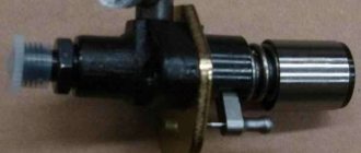
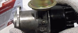
Appearance of the device
Power supply system VAZ 21099 Lada Samara
11.3.1 Power system Warning When removing and disassembling the carburetor, do not smoke or use open flame! PERFORMANCE ORDER 1. Disconnect the choke rod. 2. Remove the accelerator drive return spring. 3. Remove the spring clamp on the accelerator drive sector by prying its hole... 11.3.2 Removing and installing the carburetor Warning When removing and disassembling the carburetor, do not smoke or use open fire! PERFORMANCE ORDER 1. Disconnect the choke rod. 2. Remove the accelerator drive return spring. 3. Remove the spring clip on the accelerator drive sector by prying its hole...
11.3.3 Disassembling the carburetor Carburetor (left view): 1 - air damper 2 - starting device 3 - mixture quantity adjustment sensor-screw 4 - accelerator pump 5 - solenoid valve 6 - carburetor cover Carburetor (right view): 1 - first chamber 2 - second chamber 3 - accelerator spray...
11.3.4 Defective carburetor parts Wash the carburetor filter in gasoline and blow with compressed air. Warnings If the floats are incorrectly positioned, the operation of the carburetor will be disrupted. Therefore, be sure to check the installation of the floats according to the template (see “Adjusting the fuel level in the float chamber”). Don't clean...
11.3.5 Assembling the carburetor Notes The marking of the jets is determined by the flow rate, which is measured using micrometers. Micrometers are adjusted using standard jets. The conditional flow rate of the fuel jet is determined by the reference jet using a special method. Control during operation...
11.3.6 Adjusting the air damper actuator Before you begin: remove the air filter. Fully open damper. PERFORMANCE ORDER 1. Loosen the bolt securing the linkage to the air damper drive lever. 2. Turn the choke lever until it is fully open. 3. Recess the handle completely...
11.3.7 Adjusting the throttle valve drive Note When tightening nut 1, the valve opens, and when tightening nut 2, the valve closes. PERFORMANCE ORDER 1. Press the accelerator pedal all the way. In this case, the throttle valve of the first chamber should open completely. This can be determined by...
11.3.8 Adjusting the engine idle speed Warnings Idle speed adjustment is performed on a warm engine (coolant temperature 90–95 °C) with adjusted clearances in the valve drive and correctly set ignition timing. The air damper must be completely open. Since the adjustment...
11.3.9 Adjusting the starting device Adjusting the starting device is carried out with the carburetor removed. Before making adjustments, check the condition of the trigger diaphragm by unscrewing the four screws and removing the cover. Replace the defective diaphragm. Starting clearances, mm: carburetor 21081–1107010: air damper other...
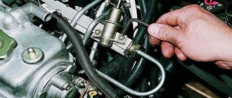
How to replace the thermostat, also known as the air filter thermostat, on a VAZ 2108-VAZ 21099?
Removal: 1) First, disconnect the tip of the air intake, from the housing inside which the air filter is located.
Note! Disconnect the tip of the air intake by turning it left and right!
2) Then, holding a wrench, use it to unscrew the bolt that secures the thermostat housing to the air filter housing.
3) When the bolt is unscrewed, remove the thermostat by disconnecting the hot air hose from it.
Note! The hose is secured with a clamp, so before disconnecting the hose, use a screwdriver to unscrew the screw securing this clamp!
Installation: The entire operation is performed in reverse order, that is:
1) First, install the new thermostat in its place, and then tighten the bolt that secures it.
2) Next, connect the air intake tip to it.
3) Finally, connect the warm air intake hose to the new thermostat. After connecting, tighten the screw of the clamp that secures this hose.
Checking the air filter thermostat for functionality:
Note! The check is carried out with the thermostat removed!
1) First, pick up the thermostat and then lower it into a suitable container of water. In this case, your water must be heated in advance to a temperature above “+35°C”.