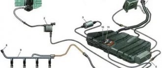
Fuel is supplied to the engine by VAZ 2114 injectors installed in the intake pipe.
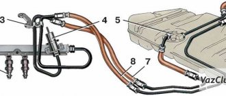
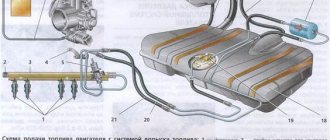
- Fuel supply system with distributed injection
- 1 – fitting for monitoring fuel pressure
- 2 – injector ramp
- 3 – bracket
- 4 – fuel pressure regulator
- 5 – electric fuel pump
- 6 – fuel filter
- 7 – fuel drain line
- 8 – fuel supply line
- 9 – nozzles
An electric fuel pump installed in the fuel tank supplies fuel through the main fuel filter and the fuel supply line to the VAZ 2115 injector ramp.
The Lada Samara 2 fuel pressure regulator maintains a constant pressure difference between the inlet pipe and the discharge line of the ramp. The fuel pressure supplied to the injectors is within 300±6 kPa when the engine is not running. Excess fuel beyond that required by the injectors is returned to the fuel tank through a separate drain line.
Before servicing fuel equipment, it is necessary to relieve the pressure in the fuel supply system of the VAZ 2114.
When disconnecting the fuel lines, do not allow the VAZ 2113 fuel to spill. To do this, wrap the ends of the tubes with a rag.
A whole complex of devices combined into one fuel system is responsible for supplying fuel to the VAZ 2114 engine. This article is dedicated to it, by studying which you will learn what the power supply system of the VAZ 2114 injector consists of, what is the principle of its operation, and what preventive measures must be taken in order for the system to work out its resource to the fullest.
The fuel supply system is the main artery of the car
PRINCIPLE OF OPERATION OF THE SYSTEM
The fuel system of the VAZ 2114, in comparison with foreign cars, is made quite simply, thanks to which a high level of its reliability and endurance has been achieved. The 2114 has an injector for injecting gasoline into the combustion chambers. The presence of an injector provides for a complex fuel dosing system, for which the ECU controller (electronic control unit) is responsible.
The VAZ 2114 fuel pump is driven electronically. The injection moment itself is calculated thanks to sensors that determine the location of the car’s crankshaft. When the fuel pump is turned on, the fuel is supplied through the transport system to the filters, where it is cleaned of impurities, and after the filters - to the fuel rail.
The fuel rail is the part of the intake manifold in which gasoline and gas are mixed in a ratio of 1 to 15 (an increase or decrease in the amount of gas can be adjusted manually, but the optimal gasoline consumption is observed precisely at the above ratio). Next, the mixture is supplied to the injectors, after which it enters the combustion chambers.
Description of the power system design
The vehicle's power system is designed to store fuel reserves, purify fuel and air from foreign impurities, and supply air and fuel to the engine cylinders.
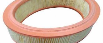
The air entering the engine cylinders is cleaned of dust by an air filter. Air filter
installed in the engine compartment on three rubber supports. The filter element is replaceable and made of special paper. To prevent contaminated air from leaking into the intake tract, there is a sealing edging at the top of the element. To replace the filter element, the filter cover is removable. The purified air passes through the mass air flow sensor through the air duct to the throttle valve.
Throttle valve
regulates the amount of air entering the engine cylinders. The damper drive from the gas pedal is cable. The damper rotates on an axis in the housing (pipe). The throttle body is secured to the receiver flange with studs. The housing has a channel for coolant. The channel is connected to the cooling system by rubber hoses. Circulating coolant through the throttle body prevents the body's internal air cavities from freezing in the winter. The housing contains fittings for connection to the absorber and the engine crankcase ventilation system.
The throttle body, with the throttle position sensor and idle speed control installed on it, form the throttle assembly.
Throttle assembly:
1 - throttle valve drive sector; 2, 4 — fittings for connection to the engine cooling system; 3 — crankcase gas outlet fitting; 5 — throttle position sensor; 6 — idle speed regulator; 7 — fitting for connecting to the adsorber; 8 — throttle valve; 9 — throttle body pipe
Air is supplied to the intake valves of the engine cylinders through the receiver and the intake manifold.
Fuel tank
steel, welded from two stamped parts. The tank is suspended from the bottom of the car on two steel clamps. The filler neck of the fuel tank is located on the right side of the vehicle and is closed with a plug. Fuel from the tank is supplied by an electric submersible fuel pump.
The pump is installed in the fuel tank. To access the pump, there is a hatch with a cover in the bottom of the car under the rear seat cushion. A strainer is installed on the inlet pipe of the fuel pump, which traps small solid particles of debris that enter the fuel tank along with gasoline. The pump is turned on by command from the ECU.
Fuel pump:
1 — protrusion for fastening the mesh filter; 2 — fuel intake pipe for connecting a strainer; 3 - body; 4 — electrical connector block; 5 - outlet (discharge) pipe for connection to the fuel module cover with a corrugated tube
From the pump, through the corrugated tube of the fuel module (see below), gasoline enters the fuel line and then into the fuel filter, where the fuel undergoes more thorough cleaning.
The fuel filter is made of paper, installed in a non-separable metal housing. The purified fuel flows through the fuel line into the fuel rail.
Engine fuel filter 11183 (1.6i):
1 — inlet pipe; 2 - body; 3 — fuel flow direction arrow (painted on the filter housing); 4 - outlet pipe
Note. The fuel filter of the 2111 (1.5i) engine has threaded connecting pipes.
The fuel rail holds four injectors and supplies fuel to them. The connection between the ramp and the injectors is sealed with rubber rings.
The fuel pressure regulator is a bypass valve that maintains in the system (fuel line) the operating pressure necessary for proper operation of the injection system.
All cars of recent years of production are equipped with a fuel vapor recovery system (in accordance with EURO II environmental requirements), where the above-fuel space of the tank is connected to the atmosphere not directly, but through the elements of this system. The system consists of a separator, safety valve, adsorber, gravity valve, adsorber purge valve, check valve, connecting pipes and hoses. The separator and gravity valve are mounted under the right rear fender of the vehicle. In the separator, gasoline vapors are partially condensed and returned back to the fuel tank. The gravity valve prevents fuel from leaking out of the tank when the vehicle turns over. The safety (two-way) valve prevents the formation of excess pressure of fuel vapor in the tank, as well as the occurrence of vacuum there caused by fuel consumption.
Location of elements of the fuel vapor recovery system in the rear of the vehicle:
1 - safety valve; 2 - separator; 3 — plug of the filler neck of the fuel tank; 4 - gravity valve
Note. The photo shows the rear bumper.
From the separator, non-condensed gasoline vapors flow through tubes and connecting hoses into the adsorber, which prevents the vapors from entering the atmosphere. An adsorber is a container where gasoline vapors are absorbed by activated carbon. When the engine is running at high crankshaft speed, the ECU sends a signal to open the canister purge valve, and gasoline vapors are sucked into the intake module receiver.
Adsorber:
1 — adsorber body; 2 - pipe for connecting the internal cavity of the adsorber with the atmosphere; 3 — adsorber purge valve; 4 — valve connecting pipe; 5 — adsorber connecting pipe
WHAT GASOLINE TO POUR IN THE VAZ-2114?
This topic has become overgrown with various conjectures and speculations, but we will try to put everything in its place.
The technical data sheet of the fourteenth indicates that the car engine requires AI-95 gasoline, and there is no reason not to trust the manufacturer’s recommendations.
Another thing is that many car owners, over their long driving experience, have accumulated rational doubts about the existence of any serious differences between 95 and 92 gasoline. Adding fuel to the fire was the recent statement by the chief engineer of the Moscow oil refinery, A. A. Abrosimov, that we do not make 95-grade gasoline in our country, and everything that is sold under its guise is either 92-grade or unknown fuel brought from somewhere.
As evidenced by reviews from VAZ 2114 owners who use exclusively 92-octane gasoline, there were no problems with the car during its service life due to fuel, and they see no point in using a more expensive analogue. However, the final decision about what to pour into the fourteenth is yours.
Replacing the fuel rail on VAZ 2113, VAZ 2114, VAZ 2115
Welcome! Fuel rail - it distributes fuel to the injectors, in addition, it regulates the pressure that will be supplied through the injectors to the car engine, that is, thanks to this thing, we can say that the car drives and not only does it drive, but it drives without interruptions in engine operation, with ramp time due to bad fuel it becomes clogged, in this case it will be enough to remove it and wash it from the inside with a special liquid to clean the injector, but you can also replace it if you have extra money, but we still recommend replacing it only in cases of its deformation, when it already has injectors do not hold on when the clamps of their fastening fall off, etc.
Note! Replacing this thing is not that difficult, you just need to know some nuances, by the way, some people even remove the receiver from the car to replace it, in fact, you don’t have to remove it and immediately proceed to replacing the ramp itself, to do this you will need: Hex keys, as well as a set of wrenches, and screwdrivers, if you are going to remove the receiver (With the receiver removed, it is much easier and more convenient to change the ramp, and if it is installed, then you will also replace it, but it will just be inconvenient , but you’ll save yourself a lot of time), then you’ll also need socket heads, an extension cord for them and a wrench and even pliers will come in handy!
Summary:
Where is the fuel rail located? It is located behind the receiver (The receiver is indicated by a blue arrow), which is why all the car repair manuals (Books) say that you need to remove the receiver from the car so that it does not interfere, but whether to do this or not, as we have already told you, is at your discretion, because that the ramp can be easily removed even without removing the receiver; by the way, for clarity, in the photo below it is indicated by a red arrow.
When do you need to change the fuel rail? Only when it is deformed, but over time it needs to be cleaned, this is done using a special liquid for cleaning injectors (You can find this in a car store), namely, the ramp is removed from the car and all four injectors are also removed from it (About that how to remove the injectors, read in detail in the article: “Replacing fuel injectors on a VAZ”) and then the inside of the ramp is washed with this liquid (The liquid can be driven into the ramp through the holes where the injectors were installed) from dirt and other types of slag.
COMPONENTS OF THE FUEL SYSTEM
The VAZ 2114 fuel system consists of the following main elements:
- Gas tank;
- Fuel pump;
- Gasoline filtration devices;
- Pipeline system;
- Fuel rail;
- Injectors;
- Waste disposal unit.
Fuel system diagram
Let's analyze each component separately.
GAS TANK
The VAZ 2114 gas tank is a container made of two equal metal parts. A neck is removed from the tank into which gasoline is poured. The neck is connected to the tank via a rubber pipe and clamps.
FUEL PUMP
The fuel pump is located directly in the tank. It has a fuel level sensor, which transmits information about the current amount of gasoline to the ECU. The gasoline pump is connected to a line through which gasoline is transported to the fuel rail. The fuel pump itself consists of several parts - coarse filters, wiring and an electric motor, which pumps fuel. As evidenced by reviews from owners of fourteenth cars, fuel pumps from the German company BOSCH have proven themselves to be the best.
FILTRATION DEVICE
The VAZ 2114 fuel injection system very much depends on the quality of the filter devices used. A bad filter will significantly reduce both the efficiency and the longevity of the entire system.
On the fourteenth, non-separable filters with a working element made of paper are installed. Such filters clog quite quickly, and they need to be changed at least once every 10-15 thousand kilometers.
FUEL RAIL
The fuel rail is located on the intake manifold housing. Its design consists of two parts, separated by a spring-loaded diaphragm. The first is the fuel one, in which the required level of gasoline pressure is set, the second is the air one, air is pumped into it, due to which the diaphragm compresses the fuel chamber and changes the pressure level in it.
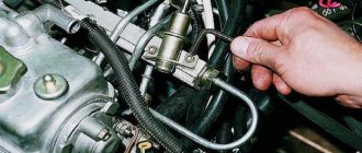
Ramp
PIPING AND HOSES SYSTEM
To circulate gasoline from the gas tank to the injectors, the fourteenth uses steel fuel lines located on the bottom of the car. The VAZ 2114 fuel supply system also provides for a return pipeline through which excess gasoline from the injectors is returned back to the gas tank.
VAZ 2114 owners are advised to carefully monitor the condition of the fuel line in order to avoid gasoline leaks. Pipes should be checked regularly for deformation and corrosion.
Supply system
The power supply system is part of the electronic engine management system, which is described in detail in a separate “Repair and Maintenance Manual for the Engine Management System with Multiport Fuel Injection.”
FUEL SUPPLY SYSTEM
The function of the fuel supply system is to ensure that the required amount of fuel is supplied to the engine at all operating conditions. Fuel is supplied to the engine by injectors installed in the intake pipe.
Rice. 2-62. Fuel supply system with distributed injection: 1 —
fitting for monitoring fuel pressure; 2 — injector ramp; 3 — fuel pressure regulator; 4 — electric fuel pump; 5 - fuel filter; 6 — fuel drain line; 7 — fuel supply line; 8 — nozzles
The fuel supply system (Fig. 2-62) includes: electric fuel pump 4, fuel filter 5, fuel lines (supply 7 and drain 6), injector ramp 2 with fuel injectors 8, fuel pressure regulator 3 and fuel pressure control fitting 1.
An electric fuel pump installed in the fuel tank supplies fuel through the main fuel filter and the fuel supply line to the injector rail.
The fuel pressure regulator maintains a constant pressure difference between the inlet pipe and the injection rail. The fuel pressure supplied to the injectors is within 300+6 kPa when the engine is not running. Excess fuel beyond that required by the injectors is returned to the fuel tank through a separate drain line.
Before servicing fuel equipment, it is necessary to relieve the pressure in the fuel supply system.
When disconnecting fuel lines, do not allow fuel to spill. To do this, wrap the ends of the tubes with a rag.
The procedure for relieving pressure in the fuel supply system:
1. Engage neutral gear and brake the vehicle with the parking brake.
2. Disconnect the wires from the electric fuel pump (see Fig. 2-63), to do this, tilt the rear seat cushion forward and remove the electric fuel pump flap.
3. Start the engine and let it idle until it stops due to fuel exhaustion.
4. Turn on the starter for 3 seconds to relieve pressure in the pipelines. After this, you can safely work on the fuel supply system.
5. After releasing the pressure and completing the work, connect the wires to the electric fuel pump.
Rice. 2-63. Location of the electric fuel pump
Electric fuel pump. The system uses a turbine-type electric fuel pump. The pump supplies fuel from the fuel tank through the main fuel filter to the injector rail. Excess fuel is returned to the gas tank through a separate drain line.
The electric fuel pump is switched on by the controller via a relay. When the ignition key is set to the IGNITION or STARTER position after being in the OFF position for more than 15 seconds, the controller energizes the relay for 3 seconds to create the required fuel pressure in the injector rail.
If the engine does not start cranking during this time, the controller turns off the relay and waits for cranking to begin. After it starts, the controller turns on the relay again.
Fuel filter 1 (Fig. 2-64) is installed under the underbody near the fuel tank 2. The filter is built into the supply line between the electric fuel pump and the fuel rail.
The filter has a steel body with threaded fittings at both ends. The filter element is made of paper and is designed to trap particles that could cause problems with the injection system.
Rice. 2-64. Fuel filter location: 1 - fuel filter; 2 - fuel tank
Removing the fuel filter:
1. Relieve pressure in the fuel supply system (see above).
2. Unscrew the nuts securing the fuel pipes to the filter. Avoid losing the O-rings installed between the filter and the tube tips.
ATTENTION. Be sure to use a second wrench on the fuel filter side when loosening the fastening nuts.
3. Remove the filter mounting clamp.
Installing the fuel filter
Check the O-rings for cuts, nicks or abrasions. Replace rings if necessary.
1. Install the filter so that the arrow on its body corresponds to the direction of fuel supply, and secure the filter with a clamp.
2. Attach the fuel pipes to the filter, tightening the fastening nuts to a torque of 20-34 Nm.
ATTENTION. Be sure to use a second wrench on the fuel filter side when tightening the fastening nuts.
3. By applying +12 V voltage to the pGc contact of the diagnostic block, turn on the electric fuel pump and make sure there are no fuel leaks.
Removing the injector ramp
When removing the ramp, be careful not to damage the connector contacts and injector nozzles.
Keep dirt and foreign materials away from open pipes and ducts. During maintenance, close the fittings and openings with plugs.
Before removal, the injector rail can be cleaned with a spray of engine cleaner. Do not dip the ramp into cleaning solvent.
1. Relieve pressure in the fuel supply system.
2. Turn off the ignition.
3. Disconnect the wire from the negative terminal of the battery.
4. Disconnect the throttle valve drive from the throttle pipe and the receiver.
5. Disconnect the inlet pipe hose from the throttle pipe.
6. Unscrew the nuts securing the throttle pipe to the receiver and, without disconnecting the hoses with coolant, remove the throttle pipe from the receiver.
7. Remove the fuel supply and drain pipes, disconnecting them from the injector ramp, pressure regulator and from the bracket on the cylinder head.
ATTENTION. Be sure to use a second wrench on the side of the fuel supply fitting of the fuel rail when unscrewing the union nut of the fuel pipe.
8. Disconnect the vacuum hose from the pressure regulator.
9. Unscrew the nuts securing the receiver and remove it from the inlet pipe.
10. Remove the injector wiring harness by disconnecting it from the injection system and injector harness.
11. Unscrew the bolts securing the injector ramp and remove it.
ATTENTION. If the injector has separated from the rail and remains in the intake pipe, both O-rings and the injector retainer must be replaced.
Installing the injector ramp:
1. Replace and lubricate the new injector sealing rings with engine oil, install the fuel rail assembly on the cylinder head and secure with bolts, tightening them to a torque of 9-13 Nm.
2. Connect the injector wiring harness.
3. Install the receiver.
4. Install the fuel pipes by tightening the union nuts attaching to the ramp and pressure regulator to a torque of 20-34 Nm.
ATTENTION. Check fuel pipe O-rings for cuts, nicks or abrasions. Replace if necessary.
Be sure to use a second wrench on the side of the ramp fitting when tightening the fuel pipe tension nut.
5. Install the pressure regulator vacuum hose.
6. Install the throttle pipe on the receiver and secure it with nuts.
7. Connect the intake pipe hose to the throttle pipe.
8. Install the throttle valve actuator and check its operation.
9. Connect the wire to the negative terminal of the battery.
10. By applying +12 V voltage to the pGc contact of the diagnostic block, turn on the electric fuel pump and make sure there are no fuel leaks.
The injector (Fig. 2-65) of the distributed injection system is an electromagnetic device that meteres the supply of fuel under pressure into the engine intake pipe.
PREVENTION OF THE FUEL SYSTEM VAZ-2114
Prevention, as a rule, comes down to regular cleaning and, if necessary, replacing the fuel pump filter and the main fuel system filter.
Also once every 25-30 thousand km. It is necessary to clean the injectors, which is performed exclusively at a service station. There are two methods for cleaning injectors, neither of which require removing them:
- Ultrasonic cleaning;
- Cleaning with a special washing liquid.
The most effective and expensive is ultrasonic cleaning, which makes it possible to bring back to life even heavily worn nozzles.
For all types of vehicles, the timing of replacing the lubricating fluid of their power unit is established by the manufacturer's regulations. It is worth noting that the figures indicated in it are very approximate (approximately 12-15 thousand kilometers), however, it is impossible to correctly calculate the order of oil changes, since this is influenced by many factors. Unfortunately, the automaker does not always take most of them into account. Continue reading →
Removing, installing and replacing the fuel pump
The first thing to keep in mind is that all work on the car’s fuel system must be carried out with the negative terminal of the battery disconnected. It would also be a good idea to do this with an empty fuel tank, especially since with the fuel module removed it becomes possible to clean the bottom of the gas tank from sediment.
The second thing it is advisable to do is to remove the pressure inside the fuel lines so as not to get a stream of gasoline in your face or into the interior of the car. This can be done using a measuring nipple on the fuel rail and a thin screwdriver.
To work you should prepare:
- curved and flat screwdrivers
- key for 17
- head for 7
- rags
Sequence of work
- Raise the rear sofa.
- We unscrew the two screws that hold the cover that blocks access to the fuel module, and disconnect the electrical connector from it.
- Using a 17mm wrench, unscrew the two fuel lines connected to the pump, being careful not to lose the O-rings, and move them to the sides.
- Newer models have clips on the pump; to remove them, press them and pull the tubes towards you.
- Using a 10mm socket, unscrew the 8 nuts that secure the pressure plate in a circle, holding the entire fuel module.
- Carefully remove it through the hole in the gas tank, having first released the fuel level sensor float.
If there is a new assembled module in stock, install it in the reverse order. If it is necessary to replace individual components: the fuel pump itself, the level sensor or the primary filter mesh, we do this by disassembling the fuel module housing and removing the corresponding parts.
This procedure is unlikely to cause any difficulties - everything is quite obvious.
For a new type of fuel pump, you need a 10mm socket and a ratchet, similarly unscrew the ring in a circle and press out the fuel line clamps.
WE RECOMMEND:
With the start of production of VAZ 2113, 2114 and 2115 cars, they used a carburetor-type engine with a volume of 1600 cubic centimeters. After long-term operation of this sample, several problems characteristic of the carburetor power system were identified. Namely: contamination of the jets, incorrect adjustment of the quality and quantity of fuel, unstable idle speed, etc. Therefore, it was decided to replace the type of power system with a more reliable one.
After the engineers chose which options to weed out and which to leave, the VAZ 2114 and 2115 with an injector engine were released. With the modification carried out, the engine design changed radically: power and speed increased, acceleration time to 100 km/h decreased. The engine size and number of valves remain the same. Let's look at what exactly the updated device contained, point by point.
Main symptoms of a malfunction
Problems with the regulator can manifest themselves in various ways:
- reduction in engine power (you can notice this when driving downhill or during acceleration);
- problems with starting the power plant (the starter rotates, but the engine does not start);
- Unstable engine operation at idle (you may often stall at intersections).
Even an inexperienced car user can notice these failures. It is important to diagnose your car in a timely manner so as not to spend money on fixing more serious breakdowns later. If you detect these signs in time, you will be able to carry out the repair yourself. Otherwise, you will have to evacuate the car to a service station.
What is an injector
The concept of injector includes complete engine control, due to the unification of all systems. The main system characteristic of this type of engine is the fuel supply. The design of this unit eliminates the carburetor, which significantly increases the resource without interruption of engine operation. The injection of the injector system is carried out directly into the combustion chamber through nozzles. It is this device that helps increase the speed and power of the VAZ 2114 and 2115, with the same valve operation.
The diagram of this power system highlights the main unit - a computer that automatically regulates fuel injection into the chamber, operation of valves, fuel pump, etc. That is, the main part of the engine injector is electrical equipment.
Features of the engine power system 11183 (1.6i)
Receiver
engine 11183 (1.6i) is made of plastic.
Engine Intake Module 11183 (1.6i):
1 — flange with an o-ring for fastening the throttle pipe; 2 - receiver with o-rings for connection to the inlet pipeline
Engine Fuel Module 11183 (1.6i):
1 — inlet pipe (for supplying fuel to the pressure regulator); 2 - outlet (discharge) pipe; 3 — module cover; 4 — fuel level indicator sensor; 5 - intake chamber; 6 — module cover guide
Fuel pump
combined with a fuel level indicator sensor and a fuel pressure regulator into a single unit -
a fuel module
(often called an electric fuel pump). Fuel from the pump (through the outlet pipe of the fuel module) enters the fuel filter. Purified gasoline is again supplied through the fuel line and through a tee to the inlet pipe of the fuel module, and then supplied to the fuel rail.
Engine fuel pressure regulator 11183 (1.6i):
1 — hole for dumping excess fuel; 2, 4 — sealing rings; 3 — holes for supplying fuel to the regulator; 5 — body; 6 - terminal for connecting the regulator to ground
Fuel rail for engine 11183 (1.6i) complete with injectors:
1 — diagnostic fitting; 2 - fuel rail; 3 — fitting for connecting to the fuel line; 4, 5, 6 and 7 - injectors
Excess fuel is released through the pressure regulator into the tank. The fuel pressure regulator is installed in the fuel module cover.
Engine power supply diagram 11183 (1.6i):
1 - nozzle; 2 - fuel rail; 3 — diagnostic fitting; 4 - adsorber; 5 - check valve; 6 — throttle assembly; 7 - gravity valve; 8 — safety (two-way) valve; 9 - separator; 10 — fuel line tubes connecting the fuel module to the fuel filter; 11 — fuel module; 12 — fuel filter; 13 - filler pipe; 14 — fuel tank; 15 — fuel line connecting the fuel module to the fuel rail; 16 — metal fuel pipe; 17 — connecting hose; 16 - fitting for connecting the fuel rail to the fuel line
Electrical equipment
On a VAZ 2114 car, such a concept as: a unified circuit of electrical appliances is simply absent. This is explained by the fact that from 1999 to 2011, the injector was modernized, incorporating more and more new components into its device that affect the final power and speed of the machine. In order to study how the electrical wiring diagram and its components work, you need to understand this individually, together with a specialist. The basis of any such system is a computer. The rest of the device may differ radically from each other, depending on the year of manufacture of the VAZ car.
Removing, installing and replacing the fuel pump
If the VAZ fuel pump does not work, the car's fuel system needs to be repaired. Before you begin repairs, you will need to disconnect the negative terminal on the car battery. In addition, work must be carried out with the car’s gas tank empty. Replacing the fuel pump is carried out by dismantling the fuel module, which makes it possible to clean the bottom of the gas tank from accumulated sediment.
In order to replace a failed device, you will need to relieve the fuel pressure inside the fuel line. This is done by unscrewing the fuel rail fitting plug using a thin screwdriver. To remove the fuel module, you will need to prepare some tools:
- figured and flat screwdrivers;
- key number 17;
- head number 7;
- rags.
If the VAZ 2114 fuel pump does not work, then to replace it you need to perform a certain sequence of operations. First, two self-tapping screws are unscrewed, which secure the cover that closes free access to the installation site of the vehicle’s fuel module. After removing the cover, the electrical connector is disconnected from the assembly.
A number 17 wrench is then used to unscrew the fuel lines, being careful not to lose the special O-rings that ensure a tight connection. After disconnecting the pipelines, they are carefully moved to the side of the fuel module, allowing full access to it.
Using head number 7, unscrew the nuts that secure the pressure plate. It ensures the retention of the entire fuel module. After removing the plate, the module is removed from the tank cavity; to do this, you first need to release the fuel level sensor float.
If the module is assembled, it is installed in place of the removed one. However, if it is necessary to replace individual components of the module, it is further disassembled and the required parts are replaced.
When carrying out these operations, it is best to use the instructions for operating and repairing the car, which, as a rule, contain photos that can clarify the essence of performing a particular operation to repair or replace components and assemblies of the car.
The use of such manuals can greatly facilitate the performance of repair work for almost every car enthusiast who is not a car service specialist.
Modern cars mainly use an injection power plant. The carburetor engine has less efficiency, so it is practically no longer produced.
The fuel pump is installed on a VAZ-2115 car directly in the fuel tank. With its help, it is possible to create a pressure within the fuel system within eight atmospheres. The fuel pump is capable of pumping 80 liters of gasoline per hour. The disadvantage of this element, which powers an 8-valve engine, is considered to be poor resistance to impurities contained in fuel. Also, you cannot turn it on if there is no fuel in the tank.
Device
An injector engine consists of several main elements. As in any car, fuel comes from the tank through the fuel line. Along the way, the combustible mixture goes through several stages of purification: a fine filter and a coarse filter. There is no strainer, such as was located on the carburetor inlet.
In general, on a VAZ car with an injector engine, instead of carburetor throttle valves, a throttle assembly is used. Its circuit is directly connected to the adsorber of the electromagnetic valves. It is he who regulates the fuel supply to the injectors.
As far as everyone knows, the correct operation of the engine directly depended on the amount of combustible mixture. It was controlled by the volume of the primary and secondary carburetor chambers, and the jets. In the version with an injector, a combination of three valves is used: two-way, safety and gravity. It is they who control that there is no overflow of the spark plug, or, conversely, a lack of fuel in the combustion chamber.
Fuel pressure control
In order for the engine to produce normal power and have synchronous operation of the valves, a fuel pressure regulator is installed in front of the injectors. With increased or decreased pressure, the regulator is activated, ensuring further operation of the piston.
Well, the last element of the device is the nozzles. They regulate injection into the combustion chamber. Since fuel is supplied to the injectors under constant pressure, they almost never clog. That is why the service life of a VAZ 2114 engine with an injector, without outside intervention, is much longer than with a carburetor.
In the period from 1999 to 2011, VAZ 2114 models with an injector engine were produced in two versions, which differed in engine capacity: 1500 and 1600 cm/cc. Their design was slightly different, not the circuit itself, but some components not related to the fuel system.
Why is this device needed?
The regulator, responsible for maintaining normal fuel pressure in the system, is in direct interaction with the power unit. According to its location, it can be located in the fuel tank or in the rail (this is where you will be able to find the regulator if you have an injection VAZ-2115). The reason for the failure of this element is often the low quality of gasoline. If you fill up at gas stations with greatly reduced prices, then it is not surprising that very soon the regulator will fail.
The fuel flows through the injectors to the intake manifold, and it is important that its pressure does not change at this moment. The regulator measures the volume of fuel required for engine operation, and also monitors the pressure in the fuel rail and intake manifold.
The main task of the RTD is to maintain the pressure difference at the same level, as well as monitor the indicators.
Purpose
The starting point where gasoline comes from is the gas tank. It is a 40-liter canister, which is absolutely sealed. If the car is used for a long time (about 5 - 10 years), then rust forms on the walls of the tank. Small parts of it are washed with gasoline and settle at the bottom. When driving over uneven surfaces, pieces of rust rise and enter the fuel system.
Considering that the cross-section of the jets is very small, in order to completely close them, a few particles of rust will be enough. So, to prevent this from happening, the car uses a fuel filter that retains all the debris from the tank.
Also, when the car is idle for a long time, gasoline vapors in the gas tank rise upward, and the watery part remains at the bottom. In this case, if you start the engine, gasoline will be supplied to the system along with water. Then, the VAZ 2114 fuel filter retains water and only allows gasoline fumes to pass through.
Of course, not one cleaning element does not last very long. This part constantly gets clogged and needs replacement very often. Fortunately, this part is not expensive, and any car owner can afford to buy it.
Operating principle and typical failures
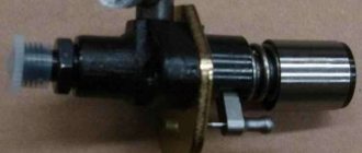
A fuel pump is a kind of small electric motor that pumps fuel and creates pressure in the fuel rail of a VAZ 2114 car. The pump is a component of the fuel module.
Structurally, the pump and electric motor are a single unit. Its electrical part is washed with fuel, which provides cooling, plus lubricates the surfaces that come into contact with each other.
Fuel pump VAZ 2114
There are many signs of breakdowns, which indicate a failure or malfunction in the fuel system, or more precisely the fuel pump. Almost every person is able to detect some of them:
- The engine does not start;
- When you try to start the engine, you cannot hear the electric motor;
- The engine runs intermittently;
- Jerking occurs when moving at low speed.
Causes
As for the reasons why the fuel pump fails, they may be:
- Fuse on the pump is broken;
- Failed relay;
- Failure of the pump electric drive;
- Poorly secured block masses;
- Damage to the pump itself;
- Missing or poor contacts at the motor terminals.
In fact, it is extremely rare for an electric motor to break down. This is due to the active cooling of the element by fuel, which not only cools, but also flushes all its components.
Shidron blower and mesh
But the centrifugal gate hydraulic supercharger suffers more often than others. The reason is small contaminants in the fuel, which end up inside the mechanism, rub against the structure and wear them out. The performance of the unit drops, the pressure decreases. This leads to the formation of the first signs of pump wear, operation noise increases, and the engine refuses to start. It is impractical to repair a broken pump; it must be completely replaced.
Device
Unlike the VAZ Classic, on the Lada 2114 model, fuel filters are installed on the highway, and not in the engine compartment. There are only two of them: fine cleaning and coarse cleaning. They differ in their structure, as well as in the quality of cleaning.
First, on the way from the gas tank to the carburetor, a coarse filter is installed. It is located on the pipe that comes out of the tank and leads into the engine. The cleaning element of such a filter is a mesh. Its purpose is to clean gasoline from large debris present in the tank. Since this mechanism is very simple in design, it does not need to be replaced, and it is enough to simply wash it with gasoline and put it back.
Further along the fuel line there is a fine filter. Its structure is already heavier. It consists of a plastic body with two pipes. The fuel enters one pipe and, after passing through the filter element, comes out of the second.
This type of filter is considered disposable. That is, it cannot be cleaned or repaired. If it gets clogged, the only solution is to replace the part with a new one. And changing this device is easy. First, loosen the clamp on the exhaust pipe. Then, remove the main hose from it and insert a new filter into it. This is done to prevent gasoline from leaking out.
The old fuel filter must be held in such a position that the outlet pipe faces upward. Next, loosen the second clamp and remove the old filter element. The fuel line hose coming from the gas tank should still face up. Once the old unit is removed, insert the hose into the inlet of the new cleaning element. That's it, the replacement is complete.
Components of the device
The VAZ 2114 fuel system includes:
- fuel mixture storage tank;
- gasoline pump;
- several types of filters;
- pipelines for transmitting flammable liquids;
- ramp with 4 nozzles;
- pressure regulator;
- cap on the tank neck.
The steel fuel tank serves as an object for storing fuel; it contains a high-pressure pump and a fuel availability indicator controller, which transmits a signal to the control panel. The pump has a coarse filter that prevents large particles of debris, rust and various impurities from entering the fuel system.
There is a fine filter near the tank; this unit guarantees thorough cleaning of the flammable liquid from the main line to the nozzles.
The injectors are placed on the fuel rail, which securely fastens them to the engine. Fuel injection is carried out using the system control unit. The pressure regulator controls the level of fluid injection between the inlet hose and the ramp line. The excess combustible mixture is returned back through the nozzles, along a separate tank drain line.
The temperature of the fluid that performs the reverse stroke increases by 6-14 degrees, this happens because the fuel circulates under the base of the machine and the blazing engine, and also rubs against the walls of the hose.
This circulation of the combustible mixture increases the temperature of the total liquid in the tank. Fuel vapors appear, which, according to a certain pattern, enter the fuel container and do not escape into the atmosphere; the fuel injection system ensures the safe capture of evaporation, destroying the vapors during engine operation.
Before carrying out repairs or preventative actions on the power system, it is important to reduce the pressure inside the unit. To prevent fuel spillage when removing the wires, it is important to secure the ends of the hose with microfiber.
The vehicles are equipped with a VAZ 2114 fuel supply system, which effectively supplies fuel at various inclinations of the vehicle, as well as when the liquid level in the tank is low.
Symptoms of malfunction
Sooner or later, any fuel filter becomes clogged and needs to be replaced. But what are the characteristic symptoms that indicate that the filter element has worn out?
The first symptoms by which it can be determined that the mechanism requires replacement is a loss of engine power. When you press the gas pedal, the car will choke and jerk. It is worth knowing one detail that will distinguish this malfunction from others - at idle speed, the engine will operate stably.
If, when you press the gas pedal, the car not only jerks, but also stalls, then this means that it is time to change the filter, since such driving can have a detrimental effect on other components and mechanisms of the VAZ 2114 car.
The next degree of filter contamination is when the car begins to stall even at low speeds. At the same time, it is impossible to move uphill because there is not enough power. The last stage, which clearly indicates that the filter needs replacement, is when the car stalls immediately after starting, or does not start at all. But experts strongly recommend not to let the cleaning mechanism reach this state. If your car has the first symptoms, then replace the filters immediately, especially since they will not take a lot of money and time to install.
How to properly check RTD
In order to independently check the pressure in the system, and therefore the correct operation of the regulator, you need to take a pressure gauge, the maximum pressure in which is up to 10 atmospheres. You should not use a device with a larger scale, as its readings will have a serious error. It connects between the fitting and the fuel pipe:
- first turn off and cool the engine;
- locate the fuel rail under the hood;
- remove the plug from the fuel pressure fitting;
- unscrew the fitting nipple using a spool valve;
- wipe the surfaces if fuel splashes appear under the influence of residual pressure;
- pull a hose with a diameter of up to 9 millimeters onto the fitting and secure it with a clamp;
- Connect the second hole of the hose to the pressure gauge.
Next, you will need an assistant, because the readings from the pressure gauge need to be read at one of four moments:
- when the ignition is turned on, the pressure should be 3 atmospheres;
- at idle speed - 2.5;
- when squeezing the fuel outflow hose - 7;
- with the hose removed on the RTD – 3.3.
If on your VAZ-2115 the measurements show different indicators, then you need to replace the regulator with a new one. To do this, it is enough to detect it in the system, dismantle it, and then return the fuel line to its original state. In the VAZ-2115, the engine of which has 8 valves or another system, the RTD is mounted at the very end of the fuel rail.
Device
The carburetor of the VAZ 2108 car consists of two main parts - upper and lower. In each of them, there are some parts and mechanisms that are directly connected to each other. Let's look at the design of the standard Solex carburetor in more detail:
- Float chamber. It houses the jets, float and throttle valve;
- The first and second chambers, with a dosing device;
- Vehicle idle system;
- Transition system located in the second chamber;
- Econostat;
- Pneumatic economizer;
- Accelerator pump;
- Gasoline starting mechanism;
- EPHH;
- System providing crankcase ventilation;
- The mechanism that controls the dampers.
Malfunctions
The main signs that the fuel pump is not pumping are as follows:
- the power plant does not work;
- when the ignition is turned on, the noise of the pump is not heard;
- if the engine is running, then interruptions occur periodically;
- the car moves jerkily.
Thus, checking whether it works is quite simple: turn on the ignition and listen. A characteristic sound will indicate that it is working properly. You need to listen in the rear seat area, because that is where the gas tank is located.
The most common breakdowns:
- fuse blown;
- relay failure;
- incorrect or unreliable ground connection;
- contamination of terminals;
- failure of the electric drive.
It should be admitted, however, that the latter happens very rarely. Due to the fact that this unit is well cooled, it is not afraid of overheating.
Most often, the centrifugal vane hydraulic supercharger, located in the pump itself, fails. The reason for this is usually the low quality of the fuel and its high contamination with foreign substances. In this case, they act as an abrasive and wear away the working surfaces, as a result of which the tightness of the seal is disrupted and, accordingly, the efficiency decreases.
The more worn the pump is, the louder it runs and the worse it pumps. If necessary, the problem can be eliminated by replacing the entire assembly, which includes both the electric motor and the pump itself.
If the fuse is blown, replace it with a new one.
The relay fails for the following reasons:
- fatigue of materials;
- incorrect installation;
- poor workmanship.
Unreliable fastening of the mass leads to regular loss of contact. An incorrect connection will prevent the pump from starting at all.
Principle of operation
On the Lada 2108, different engines were installed, from 1100 cubic meters to 1500. At the same time, the carburetor design did not change at all. Enlarged jet holes helped adjust the fuel supply for a more powerful engine.
The operating principle is quite complex. Gasoline passes through a filter at the carburetor inlet. There is also a valve that prevents the amount of gasoline in the chamber from decreasing.
From the chambers, gasoline flows through jets into wells, where it mixes with oxygen and forms a flammable mixture. Some of the gasoline is taken by the idle jet, also mixing it with air. The rest of the mixture is injected under the valve. At the place where this injection occurs, two screws are installed - the quality of the fuel and its quantity. Thanks to them, you can adjust the number of engine revolutions and the supply of gasoline. The VAZ 2108 carburetor is adjusted using a flat-head screwdriver.
The economizer serves to add fuel to the combustion chamber when the throttle valves are fully opened.
The econostat is also responsible for the additional supply of gasoline, but, unlike the economizer, it passes it through the nozzle. The econostat starts working when the engine reaches maximum power.
The accelerator pump in Solex carburetors serves for atomized injection of fuel into the float chamber. It is activated when you sharply press the gas pedal, that is, during acceleration. Its device also provides for stopping the fuel when the gas pedal is released. This will protect the mixture in the float chamber from excessive air leaks.
Acceleration pump nozzle
A starting device is installed in order to increase the amount of gasoline supplied to the float chamber. Mainly used to start the engine “cold”. Increasing or decreasing the fuel supply is carried out manually, using a choke.
After the mixture is ready, it is fed into the combustion chamber through the intake manifold opening. Since the Solex carburetor was installed on all modifications of the VAZ 2108 engine, the difference between them can only be in the size of the manifold hole. Therefore, be sure to pay attention to the diameter of the hole and the size of the gasket. This will be useful to you if you carry out repairs.
Lada 2115 Samara 2 Sport › Logbook › Fuel system and extending the life of the gas tank
After installing the power unit on the car, it came to a complete revision and replacement of some elements of the fuel system.
The first thing I decided to do was repair the fuel tank. It was removed from the body back in the summer of 2013, and had the following appearance: After washing the tank and visually inspecting its condition, a slight deformation of the bottom in the area of the fuel pump module was revealed. By its appearance, we can confidently say that it was formed when a car collided with a road obstacle. Straightening out the dent was not difficult; for this I used a metal rod, a hammer and a copper block used in plumbing.
In addition, I paid attention to the condition of the metal in the area of the weld along the entire perimeter of the tank. Crevice corrosion was present almost everywhere. This upset me a little, since this problem had to be fixed, and in the first minutes I didn’t even know how to do it. But, after further thinking about this issue, I came up with an idea.
The manufacturing technology of the fuel tank involves joining the parts of the body with an overlap, and applying one weld with through penetration, as shown in the following figure.
The described development of events is confirmed in practice and has the following picture:
To avoid adverse consequences and extend the life of the gas tank, I decided to get rid of the potential source of corrosion by cutting off all the metal from the outside after the weld.
The procedure was performed with extreme caution in order to avoid breaking the seal of the tank. I cut off the main part of the unnecessary metal using an angle grinder, trying to cut at the edge of the weld or with a slight indentation from it. Then, where the use of an angle grinder posed a danger of violating the integrity of the seam, I, armed with a file with a large notch, finally removed the remaining metal until the metal overlap was completely removed. The result is a solid face without any cracks or cavities.
To check the tightness of the tank after the modification was completed, I poured a small amount of kerosene into it and installed it in a vertical position for some time, carrying out this control on each of the four faces.
The next problem I discovered, and not only with my gas tank, is the fastening of the fuel pump module. We are talking about earlier versions of tanks that use M4 threaded studs. In most cases, such a small thread, if used carelessly, quickly becomes unusable. The main reason here, in my opinion, is nuts with insufficient height, which involves too few threads. Negligent use of threads also means excessive tightening torque of a threaded connection, which is the case in our country. As a result, the threads are cut off at the place where the nut has its final position when tightened, which is what I found on several studs on my tank.
I saw the local solution to this problem as making nuts with an increased height in order to involve more threads of the fastening joint threads.
The last thing left to do was paint the tank, and this should have completed its restoration. Places where the old paint had peeled off and bare metal was visible were cleaned and primed. I did not completely remove the old coating, I just gave it a matte finish for better adhesion of the new paint.
The welded bracket for fastening the filling pipe had to be cut off, as crevice corrosion had formed between it and the pipe. After removing it, the bracket was welded back. To prevent a relapse in the future, after painting the pipe, I filled the crack with molten gun fat from Oilwright.
To power the engine with fuel, I planned to install something more efficient. I looked towards the well-known Masuma MPU-103. I already wanted to order it from the EXIST online store through my friend CHUJOYYA, but he convincingly dissuaded me from doing so.
The essence of the belief is that there is nothing more reliable than “made in Japan”, even from a landfill. Considering the quality of the new current spare parts, I easily decided on a pump from disassembly, and CHUJOYYA placed an order in my name and address. Thanks again to him!
Having installed the tank and connected the supply and discharge lines, all that remained was to install the filler neck, deal with the gasoline vapor separation system and the separator itself, since a crack was discovered on the old one, so it definitely required replacement. To study its design, it was divided into two parts:
I would also like to draw your attention to rubber goods installed on a metal shield located under the separator: - bushing of the outboard bearing strip (2101-2202106
) 4 things.;
— sealing ring for the gas tank filler neck ( 2108-1101085
) 1 pc.
The parts are irresponsible, they are quite rare in stores, few people bother looking for them. But still, out of necessity, some car owners acquire the desire to find them and buy them. I even came across a blog post asking for help in purchasing the O-ring mentioned above.
Source: www.drive2.ru
Problems and repairs
Very often, Solex carburetors encounter a problem such as clogging of the inlet hole in the first chamber. This is due to the fact that after long-term operation of the engine, carbon particles appear on the cylinder walls, which enter the chamber along with the air entering the carburetor. Repairing this problem is quite simple. In order to clean the holes and chambers from carbon deposits, use a special liquid that is sold in every Automotive store. It eats away carbon particles and cleans the carburetor. If such a breakdown caught you on the road, and you did not have a cylinder with such a liquid at hand, then the following scheme of actions will help you:
- Without turning on the ignition, pull the choke lever towards you until it stops;
- Start the engine;
- Gradually and smoothly release the choke, and when you feel that the car is about to stall, press the gas pedal all the way. You need to provoke the opening of the second chamber, and then the carbon particles will fly out of the hole under high pressure.
Remember that this method will relieve you of the problem for a while. To completely solve it, contact a service station, where the carburetor will be repaired. Another weak point of Solex carburetors is the small hole in the idle jet. This is fraught with the fact that even a small speck can clog the hole, and the car will stall at idle. In such a situation, no repair is required. Simply remove the jet and blow it out thoroughly.
The third problem, which very often occurs on carburetors of VAZ 2108 cars, is wear of the economizer gasket. At the same time, the engine's idle speed will not be stable, and the exhaust gases will turn black. Repair is carried out by replacing the gasket.
There are rarely cases when the amount of carbon deposits entering the chamber is very large. This mainly happens to those cars that have not undergone major repairs in a timely manner. Since the previously described scheme will not help you get to the nearest service station, you need to act more radically. Experts, in this case, recommend disconnecting the breather from the carburetor, directing its flow downward, using a long hose. This will help you somehow get to the station where repairs can be carried out.
Remember to periodically clean the Breather
Don't forget that the carburetor must be adjusted correctly. The VAZ 2108 carburetor is adjusted as follows: tighten the quality screw and the quantity screw until it stops, turning them clockwise with a screwdriver. Next, unscrew the quantity screw by one and a half turns, and the quality screw by 3.5. This is a mixture adjustment with minimal spark plug wear. If the spark plugs are worn out enough, add 1 - 1.5 turns for quality. With normal settings, the Solex should provide the engine with 800 - 900 rpm at idle. Under such conditions, repairs will very rarely be necessary.
How to replace the fuel rail on a VAZ 2113-VAZ 2115?
Note! On cars of the Samara 2 family, different engines were installed and different fuel rails were also installed, but don’t pay much attention to this, and even if you have a ramp of a different type (on engines 21114 there is a ramp like the one shown in the pictures below), then the principle of removing it is practically is identical to other ramps (In this article we are looking at replacing the fuel rail of the 2111 engine) and therefore, by turning on your head and studying this article in detail, you can replace this ramp on your car!
Removal: 1) Before proceeding to removal, release all the pressure in the system using a screwdriver and the fitting that is present on the fuel rail (For more details on how to do this, read the article: “Relieving pressure on a VAZ”), after the pressure will be released from the system, you can proceed to the replacement itself, first disconnect the wire block and the connector between each other that goes to the injectors (see photo below), it is located next to the fuel pressure regulator, look more carefully and you will find it immediately , by the way, as soon as these things are disconnected from each other, remove the fuel pressure regulator itself from the rail (For information on how to do this, read the article: “Replacing the fuel rail pressure regulator on a car”).
Note! Before disconnecting the wires, it is advisable to remove the minus terminal from the battery so that no short circuit occurs. If you do not know how to remove the terminal from the battery, then in this case, study point one in the article entitled: “Replacing the battery on a VAZ”, which is located on our website!
2) Now unscrew the nut securing the fuel pipe to the side of the ramp (Indicated by a red arrow) and then disconnect the tube from the ramp, once it is disconnected, inspect the o-ring on its tip (Indicated by a blue arrow) which should be in normal condition and not in no case should there be any defects on it (cracks, tears, or the ring should not lose elasticity, in other words, make sure it is not hardened), if necessary, replace it with a new one.
3) Next, using a “5” hex wrench, unscrew the two hex head bolts (see photo 1), which secure the fuel rail to the brackets; after unscrewing, carefully remove them and do not lose the washers, which are located under the bolt heads, and in completion, carefully remove the ramp, but only it must be removed at the beginning at an even angle so that the injectors are not damaged, that is, the fuel injectors fit into the holes, if you immediately begin to pull the ramp to the side, the injectors will simply bend and break due to this, so at the beginning Carefully, without changing the lines to the top, remove the fuel rail and only after that tilt it as convenient for you and pull it out together with the injectors from the place where it is located.
Note! If, when removing the ramp, it happened that the injector remained sitting not on the ramp itself, but in the hole into which it goes, then in this case the clamp that holds this injector must be replaced and the sealing ring of this injector must also be replaced, by the way, in more detail how to replace these clamps and O-rings on the injectors, read the article to which the link is given above, and this article is called: “Replacing fuel injectors on cars”!
Installation: The new ramp is installed in its place in the reverse order of removal; before installing from the old ramp, remove all the injectors and transfer them to the new ramp, and also leave all the latches in good working order, over time they will weaken and you have to replace them with new ones.
Additional video clip: So that you can clearly see the process of replacing the ramp, in this case, study the video that is located just below, it shows the whole example on the 2111 engine, this is an engine with a volume of 1.5 liters, 8 valves, used on cars of the Samara, Tenth family family and family Samara 2.
Source
How to remove the fuel pump
Before this, you need to twist the negative terminal from the battery. Also, the gas tank must be completely empty.
To replace the pump, you will need to completely remove the fuel module. This, among other things, will allow you to clean the bottom of the tank from accumulated dirt. Before removing the module, it is necessary to reduce the pressure in the system. There is a fitting on the ramp for this.
Next you need to do the following:
- remove the protective cover to gain access to the module;
- disconnect the pump power terminal;
- unscrew the fuel hoses;
- loosen the lock of the module itself;
- remove it from the gas tank.
We should not forget that before performing the last action, you need to release the float. Replacing the entire unit is the simplest solution, since repairing its individual elements will require knowledge and extensive experience. If there is neither one nor the other, then it is better to contact a car service.
