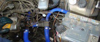
The engine fuel system is a “blood” network. The main element of this system is the fuel pump, which, like a heart, pumps gasoline from the gas tank to the engine. If for some reason this pump stops working, then it is no longer possible to start the engine. Let's look at the main reasons why the fuel pump on the Lada Kalina/Granta/Priora does not work.
Checking the fuel pump Lada Kalina/Granta
If after turning the ignition key there is no buzzing sound from the fuel pump, then the first thing to check is the fuel pump fuse and relay. In the Lada Kalina and Lada Granta mounting block, the fuel pump fuse is F21 (15A), and the fuel pump relay is K12. If the fuse is good, do the following:
- Turn on the ignition
- Remove the fuel pump relay
- Apply +12V to pin No. 11 of the diagnostic block, or place a jumper between 87 and 30 relay pins
- Check by ear that the fuel pump is turned on
If the fuel pump does not turn off, then check:
- Wiring and contacts between the fuel pump and the diagnostic block/fuel pump relay. To do this, check the voltage at the fuel pump chip using a test lamp or multimeter.
- There is no connection between the fuel pump and the vehicle ground. Apply the mixture to the fuel pump (located under the rear seat).
- The fuel pump is faulty. To check it, apply +12V directly to the contacts of the fuel pump (Attention! Remaining gasoline may ignite from a spark!).
In rare cases, the fuel pump does not work due to:
- ECU (controller) malfunction
- alarm malfunctions
Possible causes of fuel supply system failure
The fuel pump on Kalina is electric. The use of this design and operating principle is justified by a number of advantages. These are simplicity and reliability, compliance with the required characteristics in terms of fuel supply volumes and a high level of safety ensured by turning off the system when the engine stops running.
On the other hand, for high-quality work you need excellent gasoline and cooling of the fuel pump, and the process is also accompanied by an increased noise level.
- As a rule, poor quality gasoline and dirty filters lead to incorrect operation of the gasoline pump or its failure.
- If there is no response from the engine when you turn the ignition key, the problem may be due to a broken fuel pump.
- Since the main unit of the fuel system is powered by current, to troubleshoot it is necessary to check the electrical circuit going to the fuel pump.
Checking the fuel pump Lada Priora
On the Lada Priora, the fuel pump relay and its fuse are located in an additional mounting block near the left foot of the front passenger. The fuse is marked F3 (15A), and the relay is K2.
First of all, we check the fuel pump fuse, and if necessary, replace it with a similar new one. We check the wiring and the fuel pump itself in the same way as on Lada Kalina and Lada Granta cars (see above).
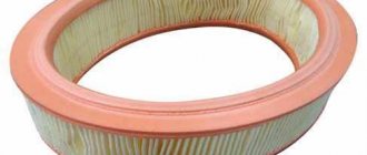
As a reminder, don't forget to change your fuel filter regularly.
Schematic electrical diagrams, connecting devices and pinouts of connectors
The fuel pump on a car is designed to supply fuel to the combustion chamber. Its operation is controlled using a relay. On a VAZ (depending on the model), the fuel supply unit can be electrical or mechanical - it all depends on the fuel supply system. On a fuel-injected car, the fuel pump is located in the tank. When the ignition is turned on, voltage is supplied to the terminals of the unit and it begins to pump fuel. If the required pressure is created in the system, the relay automatically turns off the fuel pump - the engine is ready to start.
When the ignition is turned on, the relay creates pressure in the fuel lines by turning on the fuel pump (BN) for a couple of seconds. After this, the BN will work either when the engine is cranked by the starter, or when the engine is running.
Sometimes this system needs repairs - there is nothing complicated here, and the editors of the 2Skhema.ru website will tell you how to do it yourself. Let's start with the BN pinout, then we will indicate it on the diagrams and at the end there will be instructions for replacing the fuel supply elements.
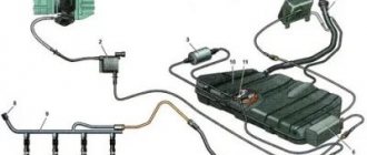
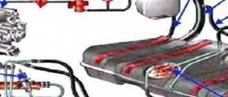
Design and operation of fuel supply
The system that provides the engine with the required amount of gasoline operates according to the following algorithm:
- After turning on the ignition, the electric fuel pump starts, raising the pressure in the line after itself to a certain level. The electrical power supply circuit of the unit is protected by a fuse.
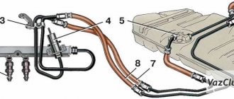
- The fuel pressure regulator (common abbreviation - RDT) is located on the line after the pump and limits the upper pressure threshold, dumping excess fuel back into the tank through a separate pipeline.
- When the crankshaft is rotated by the starter and the engine continues to operate, fuel enters the fuel rail, mixes with air and is directed to the injectors built into each cylinder. The amount of mixture supplied to the combustion chambers is controlled by an electronic unit.
- On the way to the fuel rail, gasoline goes through 2 stages of filtration. The first is a mesh installed in the tank on the suction pipe of the pump, the second is a fine filter on the gas supply line.
Reference. In various car models, 2 schemes are used for installing the RTD and laying the return pipeline - in the engine compartment or directly in the gas tank. In the first case, the standard fuel pressure in the system is 2.7...3.0 Bar, in the second - 3.8...4 Bar.
A common mistake made by ignorant car enthusiasts: if the combustible mixture does not enter the cylinders, then the fuel pump is definitely not working. Knowing the design of the fuel supply, we can assume other problems:
- the protective fuse in the electrical circuit has blown, the pump is in good working order, but does not receive power;
- the primary or secondary filter is clogged (sometimes both at once), fuel flows in small quantities or does not flow at all;
- the pressure regulator has become unusable, dumping the lion's share of the fuel back into the tank, the engine gets nothing;
- One or more injectors have failed.
To accurately determine the source of the problem, you need to check the operation of the electric fuel pump and other elements. It is not necessary to go to a service station - diagnostic work can be carried out in your own garage.
Pinout of fuel pump VAZ 2107
1 – radiator fan drive motor; 2 – mounting block block; 3 — idle speed sensor; 4 – engine ECU; 5 – potentiometer; 6 – set of spark plugs; 7 – ignition control unit; 8 – electronic crankshaft position sensor; 9 – electric fuel pump; 10 – indicator of the number of revolutions; 11 – lamp for monitoring the health of electronic systems and the brake system; 12 – ignition system control relay; 13 – speedometer sensor; 14 – special factory connector for reading errors using the BC; 15 – injector harness; 16 – adsorber solenoid valve; 17, 18, 19,20 – fuse box for repairing the mounting block that protects the injection system circuits; 21 – electronic fuel pump control relay; 22 – electronic relay for controlling the exhaust manifold heating system; 23 – exhaust manifold heating system; 24 – fuse protecting the heater circuit; 25 – electronic air sensor; 26 – coolant temperature control sensor; 27 – electronic air damper sensor; 28 – air temperature sensor; 29 – pressure control sensor and low oil pressure lamp.
You can check the fuel pump on a VAZ 2107 simply by checking the voltage at its connection block with a tester. The presence of voltage will indicate a malfunction of the electric motor. Instead of a tester (multimeter), you can use a test lamp to diagnose a malfunction.
In the absence of one, this can be done by disconnecting the connection block for the fuel pump and fuel level control and applying voltage with wires from the battery to the place where the gray wire is connected +12 and to the place where the black wire is connected - minus. A humming pump will indicate a faulty fuse, power circuit or ECU.
Repair parts
It is worth carrying out independent equipment repairs if you are completely sure that the malfunction lies precisely in it. A large number of plastic elements make the pump very fragile. For this reason, care must be taken when disassembling.
- Using a screwdriver, you need to pry up and remove the drain module of the part.
- The ground wire will be disconnected from the equipment.
- The intermediate wire connector is disconnected (from the inside).
- The pressure regulator is removed.
- The gasoline element module is removed by pressing the plastic retainer.
- The filter mesh is removed from the housing. If it is dirty, it can be cleaned. But it is more advisable to install a new mesh.
Damaged elements must be repaired or replaced with new parts. At the same time, it is advisable to replace the fine fuel filter. It is located near the jack cup in the right rear wheel arch. The equipment is assembled in the reverse order.
If Kalina's fuel pump does not work, the reasons often lie in a malfunction of the part itself. This equipment is inexpensive. It is quite possible to remove the unit and replace it with a working one yourself. It is better to purchase original spare parts.
Source
Pinout BN VAZ 2108, 2109, 21099
The fuel pump activation relay (2) is shown by an arrow.
1 — nozzles; 2 — spark plugs; 3 — ignition module; 4 — diagnostic block; 5 - controller; 6 — block connected to the instrument panel harness; 7 - main relay; 8 - main relay fuse; 9 — electric fan relay; 10 — controller power supply fuse; 11- electric fuel pump relay; 12 — fuel pump power circuit fuse; 13 — mass air flow sensor; 14 — throttle position sensor; 15 — coolant temperature sensor; 16 — idle speed regulator; 17 — knock sensor; 18 — crankshaft position sensor; 19- oxygen sensor; 20- APS control unit; 21 — APS status indicator; 22 — speed sensor; 23 — electric fuel pump with fuel level sensor; 24 — solenoid valve for purge of the adsorber; 25 — block connected to the ignition system harness; 26 — instrument cluster; 27 — ignition relay; 28 — ignition switch; 29 — mounting block; 30 — electric fan of the cooling system;
How to check if the fuel pump is working properly
1200 rub. for the photo report
We pay for photo reports on car repairs. Earnings from 10,000 rubles/month.
Write:
The causes of fuel pump failure are not always the same, and the devices themselves can be electrical or mechanical. Diagnostics of the performance of these types has differences, so we will consider ways to check the operation of gasoline pumps separately. However, the operation of the fuel pump can be checked in a maximum of 7 stages.
The need to check the fuel pump appears when the following signs of malfunction occur:
- the engine stalled;
- the car moves unevenly, jerkily;
- the engine idles unstable and does not start;
- there are “floating” speeds;
- increasing noise, whistling when the car is moving.
VAZ 2110 fuel pump pinout
If the fuel pump works directly when connected to the battery, then you will have to ring the wires going from it to the fuel pump relay, and if it does not work, then either replace it with a new one, or you will have to disassemble it and look for a fault inside the fuel pump.
Signs of trouble
There are several signs by which you can determine that the Kalina fuel pump is not working:
- the car does not start or stalls almost immediately;
- “Kalina” twitches when moving;
- the car does not develop maximum speed;
- extraneous noise or grinding noise coming from the fuel tank.
Similar symptoms are also observed when the fuel filter is clogged. Therefore, before removing the fuel pump on the viburnum, first replace the filter element. If the “symptoms” do not disappear, repair or replace the fuel module.
Pinout BN VAZ 2113, 2114, 2115
— block headlights; — gearmotors for headlight cleaners*; - fog lights*; — ambient temperature sensor; - sound signals; — engine compartment lamp switch; — electric motor of the engine cooling system fan; — generator; — low oil level indicator sensor; — washer fluid level sensor; — front brake pad wear sensor; — wire tips connected to the common windshield washer pump**; — windshield washer pump; — headlight washer pump*; — wire ends for connecting to the rear window washer pump on VAZ-2113 and VAZ-2114 cars; — low oil pressure indicator sensor; — engine compartment lighting lamp; — wire lug for connecting to the wiring harness of the engine control system; — gear motor for windshield wiper; — starter; — a block connected to the wiring harness of the ignition system on carburetor cars; — coolant temperature indicator sensor; — reversing light switch; — low brake fluid level indicator sensor; - accumulator battery; — low coolant level indicator sensor; — relay for turning on fog lights; - mounting block; — brake light switch; — plug socket for a portable lamp; — hydrocorrector scale illumination lamp; — switch for the parking brake indicator lamp; — block for connecting a backlight lamp; — switch for instrument lighting lamps; - Understeering's shifter; - hazard warning switch; — front seat heating element relay; — ignition switch; — rear fog light circuit fuse; - fuse for the front seat heating elements; — door lock circuit fuse; — front ashtray illumination lamp; — ignition relay; - cigarette lighter; — glove box lighting lamp; — switch for the glove compartment lighting lamp; — heater fan electric motor; — additional resistor for the heater electric motor; — heater fan switch; - heater switch illumination lamp; — lamp for illuminating the heater levers; — gear motors for electric windows of the front doors; — power window switch for the right front door (located in the right door); — gear motors for locking front door locks; — wires for connecting to the right front speaker; — gearmotors for locking rear doors; — wires for connecting to the right rear speaker; — door lock control unit; — wires for connection to radio equipment; — headlight cleaner switch*; — rear window heating element switch; — relay for turning on the rear fog lights; — block for connection to the heating element of the right front seat; — rear fog light switch; — switch for the heating element of the right front seat; — fog light switch*; — switch for external lighting lamps; — left front seat heating element switch; — block for connection to the heating element of the left front seat; — wires for connecting to the left front speaker; — power window switch for the left front door (located in the left door); — power window switch for the right front door (located in the left door); — wires for connecting to the left rear speaker; — side direction indicators; — courtesy light switches on the front door pillars; — courtesy light switches on the rear door pillars; - lampshade; — ceiling lamp for individual interior lighting; — block for connecting to the wiring harness of the electric fuel pump; — trunk light switch; — instrument cluster; — trunk lighting lamp; — display unit of the on-board control system; - trip computer*; — block for connecting the wiring harness of the engine control system; — rear exterior lights; — rear interior lights; — pads for connecting to the rear window heating element; — license plate lights; — additional brake signal located on the spoiler.
Replacing an electric fuel pump on a VAZ
- Reduce pressure in the fuel supply system.
- Using the fuel supply hose tip clamp, disconnect 2 hoses in turn.
- Unscrew the 8 nuts around the circumference of the clamping ring and remove it.
- A wire with negative polarity is attached to one of the nuts; it must be removed carefully.
- We take the electric pump block out of the fuel tank, tilting it slightly, to keep the fuel level indicator sensor lever intact, otherwise it will produce incorrect parameters.
- Remove the sealing rubber ring of the fuel block. If its properties are lost, the product must be replaced.
- Install the pump in reverse order.
When installing fuel hoses, focus on the direction of fuel supply indicated by the arrows, and the installation arrow on the electric pump cover should point towards the rear of the car!
The module has been removed, what next?
Having disengaged the four latches, the module cover is disconnected from the “glass”. Then, the “glass” can be cleaned, the pump screen can be replaced, and so on. Details are illustrated in the photo:
The mesh will be fixed in front of the intake hole
The module is assembled in the reverse order. And when installing it in place, you need to make sure that the plastic protrusion coincides with the slot on the tank:
Here are a couple more tips:
- Do not turn on the pump motor “in the air” (the windings overheat);
- The module is replaced together with the sealing ring, which must be included in the kit.
Where is the fuel pump relay located?
Where is the fuel pump relay located? The installation location of the relay varies depending on the make of the car. Most often, it is located under the hood, in the fuse and relay box.
The fuel pump relay is designed in the circuit to prevent accidental application of high voltage to the fuel pump winding. The relay is standard and consists of a plastic body and coils with contacts. It is located in the car interior near the console. To access it, you need to remove the protection cover.
In appearance, it is a small box that resembles a “plug” with an American type of output. Each terminal has a marking that indicates the following: 31 – mass; 30– +12V constant (regardless of ignition); 15– +12 with the ignition on; 50– +12 when the starter is running; TD – signal from the ignition system; TF – engine temperature signal from the injection control unit KE. Outputs: 87 – supplies power to the fuel pump; 87H – oxygen sensor heating; 87V – turns on the starting injector.
But sometimes the fuel pump does not turn on when the key is turned in the ignition. With what it can be connected? First of all, the fuse, although if it had blown, it would not work at all. Maybe the contact is bad?
If the electric fuel pump does not show any signs of life when the ignition is turned on, this does not mean that it has burned out. The cause of the malfunction may also be a relay. The easiest way to test your hearing is that when you turn on the ignition, the relay should click. If you don’t hear a click, there is a high probability that the “relay” is faulty.
It’s easy to check the functionality of the pump itself, so we do this:
- remove the protective casing, under which there is a block with relays and fuses;
- we unscrew the fastenings of the block, remove it, it remains attached to the wires;
- we pull the RB out of the block, place a jumper between two opposite contacts, thus directly supplying power to the BN;
- if with such a connection the electric motor of the pump begins to make noise, it means that the BN itself is working, most likely the fault is hidden in the relay;
- if there is no voltage on any of the contacts on the RB block, you should look for a break in the wiring; there may also be poor contact at the place where the wire is attached to the terminal.
Comments
Guests cannot leave comments on the site, please log in.
Products for LADA at the best price
A selection of accessories for LADA from AliExpress
Car : Lada Kalina. Asks : Igor MMM. The essence of the question : the fuel pump is not buzzing, what should I do?
Good afternoon. When I turn the key in the ignition, the fuel pump stops humming . The starter turns. But the car won't start. I raised the backrest, reached to the pump wires, there is no voltage there when turned on. Where to start diagnostics?
General diagram of electrical equipment of VAZ 1118
1 — block headlight; 2 — windshield wiper gear motor; 3 - generator; 4 - battery; 5 - starter; 6 — sound signal; 7 — hood open sensor; 8 — power window switch for the right front door; 9 — motor-reducer for window lifter of the right front door; 10 — electric pump for windshield washer; 11 — connecting blocks of wires for connecting the right (front) speaker of the audio system; 12 — electric drive for locking the lock of the right front door with an open door sensor; 13 — ambient air temperature sensor; 14 — connecting block of the wiring harness for connection to the engine control system harness; 15 — electric drive for locking the left front door lock (with an open door sensor and a central locking switch); 16 — sensor of insufficient brake fluid level; 17 — connecting blocks of wires for connecting the left (front) speaker of the audio system; 18 — right front door power window switch (installed on the driver’s door); 19 — left front door power window switch; 20 — central locking switch; 21 — motor-reducer for window lifter of the right front door; 22 — remote control unit; 23 — immobilizer control unit (APS-6); 24 — mounting block; 25 — instrument panel; 26 — right side turn signal; 27 — glove box lighting lamp; 28 — switch for the glove compartment lighting lamp; 29 — brake signal switch; 30 — ignition switch (lock); 31 — lighting control unit; 32 — steering column switches; 33 — left side direction indicator; 34 — connecting blocks of wires for connecting the left (rear) speaker of the audio system; 35 — electric drive for locking the left (rear) door with an open door sensor; 36 — electric heater fan; 37 — additional heater resistor; 38 — heater switch; 39 — alarm switch; 40 — reverse lock solenoid switch; 41 — rear window heating switch; 42 — connecting blocks of wires for connecting the right (rear) speaker of the audio system; 43 — electric drive for locking the right rear door lock (with a door open sensor); 44 — fuel module of the engine control system; 45 — reverse light switch; 46 — parking brake warning lamp switch; 47 — cigarette lighter; 48 — reverse lock solenoid; 49 — connecting blocks of wires for connecting the head unit of the audio system; 50 — backlight lamps on the trim of the center console of the instrument panel; 51 — electric power steering control unit; 52 — interior lamp; 53 — rear light; 54 — block for connecting the electric drive for locking the trunk lid lock*; 55 — luggage compartment lid open sensor; 56 — license plate lights; 57 — additional brake light; 58 — rear window heating element; 59 — luggage compartment lighting lamp.
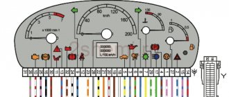
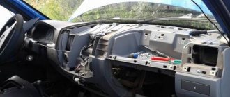
Lada Kalina dashboard diagram
1,2,3,4 — blocks of the instrument panel wiring harness to the blocks of the rear wiring harness; 5,6 — blocks of the instrument panel wiring harness to the blocks of the front wiring harness; 7 — block of the instrument panel wiring harness to the block of the wiring harness 8 — block of the instrument panel wiring harness to the block of the front wiring harness; 9 — lighting control module; 10 — ignition switch; 11 — on-board computer mode switch; 12 — windshield wiper switch; 13 — sound signal switch; 14 — light signaling switch; 15 — instrument cluster; 16 — evaporator temperature sensor; 17 — interior air temperature sensor; 18 — air conditioner switch; 19 — controller of the automatic climate control system; 20 — heater damper gearmotor; 21 — rear window heating switch; 22 — alarm switch; 23 — brake signal switch; 24 — cigarette lighter; 25 — electric amplifier control unit; 26,27 — blocks of the instrument panel wiring harness to the radio; 28 — backlight lamp for the heater control panel; 29 — illuminator; 30 — mounting block: 31 — heater electric motor switch; 32 — heater electric motor; 33 — additional resistance of the heater electric motor; 34 — glove box lighting; 35 — glove box lighting switch; 36 — control unit of the APS-6 automobile anti-theft system; 37 — driver airbag module; 38 — passenger airbag module; 39.40 — blocks of the instrument panel wiring harness to the blocks of the ignition system wiring harness.
KZ - additional starter relay; K4 - additional relay; K5 - relay-interrupter for direction indicators and hazard warning lights; K6 - windshield wiper relay; K7 - headlight high beam relay; K8 - sound signal relay; K9 - relay for turning on fog lights; K10 — relay for turning on the heated rear window; K11 — electric seat heating relay; K12 - air conditioning compressor clutch activation relay;
Instrument panel wiring harness - 11186-3724030-20.
Ignition system diagram Lada Kalina Lux
1 — oil pressure warning lamp sensor; 2 — coolant temperature indicator sensor; 3 — additional fuse block; 4 — fuses for the electric fan of the engine cooling system; 5 — electric fuel pump relay; 6 — relay for the electric fan of the engine cooling system; 7 - ignition relay; 8 — relay 2 of the electric fan of the engine cooling system; 9 — relay 3 of the electric fan of the engine cooling system; 10 — electric fan of the engine cooling system; 11 — throttle position sensor; 12 — idle speed regulator; 13 — coolant temperature sensor; 14 — diagnostic block; 15 — ignition system harness block to the instrument panel harness block; 16 — solenoid valve for purge of the adsorber; 17 — speed sensor; 18 — ignition system harness block to instrument panel harness block 2; 19 — mass air flow sensor; 20 — crankshaft position sensor; 21 — oxygen sensor; 22 - controller; 23 — rough road sensor; 24 — diagnostic oxygen sensor; 25 — ignition coil harness block to the ignition system harness block; 26 — ignition coils: 27 — ignition system harness block to the ignition coil harness block; 28 — spark plugs; 29 — nozzles; 30 - resistor; 31 — air conditioning system pressure sensor; 32 — blocks of the ignition system harness and injector wiring harness; 33 - phase sensor; 34 - knock sensor.
Ignition system wiring harness -11184-3724026-10. Ignition coil wiring harness -1118-3724148-00. Injector wiring harness -11184-3724036. A - to the “plus” terminal of the battery.