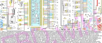
Detailed color diagrams of the VAZ 2114 wiring (carburetor, injector) are provided with a description of the electrical equipment for various modifications.
The information is intended for self-repair of cars. Many electrical circuits are divided into several sections for ease of viewing via a computer or smartphone; there are also circuits in the form of one picture with a description of the elements - for printing on a printer. The VAZ 2114 (Samara-2) car is built on the VAZ 21093 platform and is an improved version of it. The first prototype of the hatchback was assembled back in 2000. A year later, the Volzhsky Automobile Plant produced the first pilot batch of 50 VAZ-2114 cars, and in the same 2001 the hatchback was first introduced to the market. The interior features a new instrument panel, a new steering wheel, an adjustable steering column, power windows and a new heater. Years of production 2114: 2001—2013
The fourteenth model was previously equipped with a 1.5 liter eight-valve engine, borrowed from the VAZ 2111 model with an injector. A little later it was replaced by the VAZ 11183-1000 version, which complies with the Euro-3 standard. The VAZ 2114 injector received a more powerful engine, and this is one of the reasons that the wiring of the 2114 has also changed.
A wiring harness has been added for connecting to the electronic switch. A harness has also appeared for connecting to the ignition module terminal.
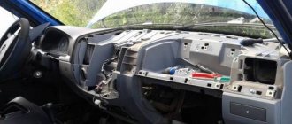
Replacing high-voltage wires will require additional attention, because the connection procedure depends on the year of manufacture of the car. Until 2004, 4-pin ignition modules were installed, and after that - 3-pin. Connecting the adsorber valve to the injection system controller also provided another additional element. An adsorber is an electromechanical device used for ventilation and removal of condensate in a gas tank. Complications also affected the interior part. The dashboard received improvements in the form of the appearance of a BC (on-board computer), a new instrument panel and a change in the position of the glove compartment.
Why the wipers don't work
In this article, we will analyze the main possible malfunctions of wipers and find ways to solve the problem.
The windshield wiper is a very important element of the car, due to its malfunction, movement is prohibited, according to traffic regulations, and in general, it is life-threatening.
It is worth noting that the mechanism is designed for a long service life. Therefore, malfunctions usually arise due to improper operation. It is also worth taking into account that most breakdowns of the glass cleaning system occur in the winter.
This is probably the most basic mistake of all car enthusiasts; many will remember themselves “in their youth.”
It’s winter, I get into the car, start it, turn on the wipers, they jerk a little and that’s it. In this case, the breakdown could have occurred either electrically (for example, a fuse in the electric motor) or mechanically (the motor itself), and it occurred due to the fact that the blades froze and stuck to the windshield.
Reasons for non-working wipers on VAZ
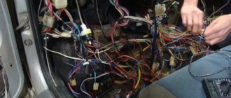
So, why don’t the wipers work on the VAZ 2114? This nuisance is especially annoying in winter or autumn, when frosts occur at night, and during the day, when you urgently need to go, it starts raining and snowing, which makes the road completely invisible. To begin with, you should not run windshield wipers on a frozen car with windows covered with frost. The rubber bands of the brushes easily freeze to the glass, and when the motor tries to move from its place, it cannot withstand the load and burns out. Second. When checking windshield wipers, pay attention to the chips, connectors, contacts, and wire ends. From prolonged use, especially when the car is left in the yard overnight, the contacts become sour and stop conducting current. In this case, they must be washed with special liquids, having previously been de-energized, or cleaned with sandpaper.
Fuses and relays
Checking the VAZ 2114 wipers should start with the fuses. There are two of them in the mounting block. We pay attention to the second fuse - F 16. The problem will definitely be in it if, along with the brushes, the turn signals and several indicator lamps on the dashboard refuse to work.
To replace the fuse, there is a special clothespin on the cover of the mounting block, with the help of which the protective device is carefully removed from the socket, and a new one is inserted in its place. A relay malfunction is indicated by the absence of intermittent operation of the front windshield wipers. You can check it by replacing it with a known working device, or with a multimeter in ohmmeter mode. If, when installing another relay, the wipers work, then the problem is there. Otherwise, you will need to check the wiper switch. When checked with an ohmmeter, a working relay on pins 85-86 should show several hundred ohms. And one more small nuance: when voltage is applied to a working relay, a characteristic click is heard. There will be no click on a faulty relay. The relay, like the fuses, cannot be restored. They need to be replaced with new ones.
Wiper switch
The wiper switch on the VAZ 2114 is located under the steering wheel. Its malfunction is indicated by the absence of any response to pressing. The switch can be easily removed:
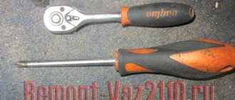
- First, use a Phillips screwdriver to unscrew the screws. Their location is shown by arrows.
- The lever that locks the steering wheel moves down until it stops.
- Then remove the top trim from the steering column.
- We release the wiper switch from the clamps and remove it.
Remove the contacts from the switch. Take the new switch and insert it in the reverse order. We check for functionality.
Useful : 4 reasons why wipers may work on their own
Geared motor
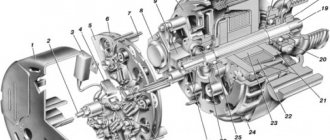
The wipers are driven by a gear motor. The performance of the motors is checked by direct connection to the battery. To do this, it is disconnected from the windshield wiper electrical circuit and connected to the battery. Below is a diagram of a gearmotor that will help, if necessary, disassemble and repair this mechanism.
One of the most common engine problems is brush wear. It is recommended to blow the cavity of the disassembled engine with compressed air to remove coal dust, check the brushes and, if necessary, replace them. Check and polish the commutator. Make sure that the springs in the brush holders are also in good condition. If the collector is badly burned, the motor will have to be replaced with a new one. During assembly, it is important to install the crank correctly. It should be directed towards the electric motor and installed parallel to the wiper rod.
Useful : Wipers on VAZ 2114 work slowly (7 reasons)
Electrical diagram
- Headlights;
- Geared motors for headlight cleaners;
- Fog lights;
- Ambient temperature sensor;
- Sound signals;
- Engine compartment lamp switch;
- Engine cooling fan electric motor;
- Generator;
- Low oil level indicator sensor;
- Washer fluid level sensor;
- Front brake pad wear sensors;
- Wire ends connected to the common windshield washer pump*;
- Windshield washer pump;
- Headlight washer pump;
- Wire lugs for connecting to the rear window washer pump on VAZ-2113 and VAZ-2114 cars;
- Low oil pressure indicator sensor;
- Engine compartment lamp;
- VAZ-2111 engine:
Wire lug for connection to the wiring harness of the engine control system
VAZ-21083 engine:
Electric fan switching sensor; - Windshield wiper gear motor;
- Starter;
- VAZ-21083 engine:
Block connected to the ignition system wiring harness; - Coolant temperature indicator sensor;
- Reversing light switch;
- Insufficient brake fluid level indicator sensor;
- Accumulator battery;
- Insufficient coolant level indicator sensor;
- Relay for turning on fog lights;
- Mounting block;
- Brake light switch;
- Portable lamp socket;
- Illumination lamp for the headlight hydrocorrector scale;
- Parking brake warning lamp switch;
- Block for connecting a backlight lamp;
- Instrument cluster lamp switch;
- Understeering's shifter;
- Hazard switch;
- Front seat heating element relay;
- Ignition switch;
- Rear fog light circuit fuse;
- Front seat heating elements circuit fuse;
- Door lock circuit fuse;
- Front ashtray illumination lamp;
- Ignition relay;
- Cigarette lighter;
- Glove compartment lamp;
- Glove compartment lamp switch;
- Heater fan motor;
- Additional resistor for heater fan motor;
- Heater fan switch;
- Heater fan switch illumination lamp;
- Heater lever illumination lamp;
- Gear motors for power windows of front doors;
- Right front door power window switch (located in the right door);
- Gear motors for locking front door locks;
- Wires for connecting to the right front speaker;
- Rear door locking motors;
- Wires for connecting to the right rear speaker;
- Door lock control unit;
- Wires for connection to radio equipment;
- Headlight wiper switch;
- Rear window heating element switch;
- Relay for turning on rear fog lights;
- Block for connection to the heating element of the right front seat;
- Rear fog light switch;
- Right front seat heating element switch;
- Fog light switch;
- Outdoor lighting switch;
- Left front seat heating element switch;
- Block for connection to the heating element of the left front seat;
- Wires for connecting to the left front speaker;
- Left front door power window switch (located in the left door);
- Right front door power window switch (located in the left door);
- Wires for connecting to the left rear speaker;
- Side direction indicators;
- Lamp switches on the front door pillars;
- Light switches on the rear door pillars;
- Central interior lamp;
- Front interior lamp;
- Block for connecting to the wiring harness of the electric fuel pump;
- Trunk light switch;
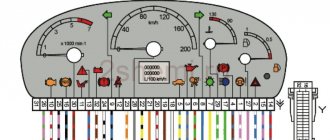
- Instrument cluster;
- Trunk light;
- On-board control system signaling unit;
- Trip computer;
- VAZ-2111 engine:
Block for connecting the wiring harness of the engine control system; - Rear exterior lights;
- Rear interior lights;
- Pads for connecting to the rear window heating element;
- License plate lights;
- Additional brake signal located in the spoiler.
Connection diagram for wipers via relay VAZ 2114
VAZ 2113, 2114, 2115 cars considered
Attention! The location of fuses and relays in the blocks may differ depending on the year of manufacture and vehicle equipment. You can see earlier modifications of fuse blocks on this page.
Fuses for the VAZ 2114 injector and VAZ 2115 injector are also described on this page.
Where are the fuses and relays located?
The main part of the fuses and relays is located in the mounting block of the engine compartment.
To get to the block you need to press two latches and remove the cover
Using pliers installed in the block, remove the fuses
On the inside of the cover there is a diagram of the location of fuses and relays.
Click on the image to enlarge.
Fuse mounting block 2114-3722010-60
Many have encountered such a slight inconvenience in the operation of the standard windshield wiper of the VAZ 2109: when the windshield washer is turned on for a short time, the blades make 3 strokes, although the last stroke of the brush is already made on dry glass, and two strokes would be enough to remove all the water that was splashed washer.
This inconvenience, as it turns out, can be easily eliminated. To do this, we buy a new windshield wiper relay (if something doesn’t work out, you can insert the old one and thus not be left without wipers) type 526.3747, or another similar one - the markings may differ depending on the relay manufacturer. In the circuit of this relay, you need to replace resistor R4. The standard one has a nominal value of 130 kOhm, we need to set it smaller, within the range of 40 kOhm - 70 kOhm. I have 56 kOhm. You can find one at points selling radio components, it costs a penny, or you can remove it from old equipment.
Relay location in the black box
VAZ 2109 wiper relay diagram
The internal design of such a relay can be different:
In all cases, the resistor we need is connected to the 4th leg of the microchip. It is highlighted in the pictures above.
By the way, this modification is also relevant for VAZ 2114-2115, VAZ 2110, Lada Kalina, Lada Granta - for all models where this type of relay is used.
New relays may have a fundamentally different design. For example, I came across this relay marked 723.3777 from the Energomash plant:
Relay 723.3777 Energomash. We can't change it
We cannot remake such a relay, so we can leave it as a spare (original), and we will solder the original one, removed from the mounting block:
We figured out the number of brush strokes. Now one more thing.
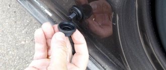
When you first press the lever to wash the glass, it usually happens like this: the brushes have already started moving, but there is no water on the glass yet. This is due to the fact that the pump needs time to drive water through the tubes from the reservoir to the washer nozzle. This situation can be corrected by installing a check valve in the tube to prevent water from flowing from the tubes back into the tank when the pump is not running. Personally, this point doesn’t bother me much, since the brushes run dry only the first time they are turned on, and installing a check valve increases the resistance to water flow in the pipes of the already weak washer pump, so I have not done such a modification on my car and do not plan to.
Engine control circuit for VAZ 2111 (January 5.1, Bosch M1.5.4N)
- Fragment of the mounting block;
- Electric engine cooling fan;
- Automotive anti-theft system status indicator;
- Automotive anti-theft system control unit;
- Coolant temperature sensor;
- Air flow sensor;
- Throttle pipe;
- Block connected to the throttle position sensor;
- Block attached to the idle speed control;
- Controller;
- A block connected to the air conditioner wiring harness;
- Oxygen sensor;
- Knock sensor;
- Crankshaft position sensor;
- Speed sensor;
- Adsorber;
- Accumulator battery;
- Main relay;
- A block connected to the anti-lock brake system wiring harness;
- Diagnostic block;
- Main relay circuit protection fuse;
- Controller protection fuse;
- Fuse for protecting the electric fuel pump and its relay;
- Relay for turning on the electric fuel pump;
- Electric fan switch relay;
- A block connected to the instrument panel wiring harness;
- A block connected to the instrument panel wiring harness;
- Ignition module;
- Electric fuel pump with fuel level sensor;
- Spark plug;
- Injectors;
- F — Front harness wire going to the “B+” terminal of the generator; G - Front wiring harness wires.
Motor malfunctions and solutions
Let's look at what to do if the windshield wiper motor does not work, and what can cause such problems. There are several options:
1. The electric motor does not work, the bimetallic fuse is inactive, and the fusible insert responsible for powering the wipers is intact. In this case, you need to check the serviceability of the wiring, the quality of connections of all contacts, determine any existing damage and eliminate them.
If everything is fine with the wiring, then you should check the wiper switch. If it acts up, just replace it. The engine itself may not work - this often happens when brushes stick or contact connections burn.
In this case, you need to repair the windshield wiper motor - inspect it, replace faulty elements, and clean dirty components. It is important to check the integrity of the wiring that connects the electric motor and the block.
Engine control diagram for VAZ 2111 - Euro-2 (Bosch MP7.0)
- Fragment of the mounting block;
- Electric engine cooling fan;
- Automotive anti-theft system status indicator;
- Automotive anti-theft system control unit;
- Coolant temperature sensor;
- Air flow sensor;
- Throttle pipe;
- Block connected to the throttle position sensor;
- Block attached to the idle speed control;
- Controller;
- A block connected to the air conditioner wiring harness;
- Oxygen sensor;
- Knock sensor;
- Crankshaft position sensor;
- Speed sensor;
- Adsorber;
- Accumulator battery;
- Main relay;
- A block connected to the anti-lock brake system wiring harness;
- Diagnostic block;
- Main relay circuit protection fuse;
- Controller protection fuse;
- Fuse for protecting the electric fuel pump and its relay;
- Relay for turning on the electric fuel pump;
- Electric fan switch relay;
- A block connected to the instrument panel wiring harness;
- A block connected to the instrument panel wiring harness;
- Ignition module;
- Electric fuel pump with fuel level sensor;
- Spark plug;
- Injectors.
- F — Front harness wire going to the “B+” terminal of the generator; G - Front wiring harness wires.
The order of conditional numbering of plugs in blocks:
- A - Controller; B — Control unit of the automobile anti-theft system; B — Indicator of the status of the automobile anti-theft system; G - Pads 26; D - Throttle pipe; E - Air flow sensor; F - Electric fuel pump and oxygen sensor; 3 — Speed sensor; And - Ignition module.
Purpose of plugs in block 26:
- To the low-voltage tachometer input in the instrument cluster;
- —
- To the engine management system control lamp in the instrument cluster (from the controller);
- To the dome light switch located on the driver's door pillar;
- To the engine control system control lamp in the instrument cluster (+ power supply);
- To the trip computer (fuel consumption signal);
- To the instrument cluster (vehicle speed signal);
- To terminal “15” of the ignition switch (plug 4 of the switch block)
Repair
To troubleshoot problems with the wipers on your VAZ 2109, it is not at all necessary to contact a service station. The work can be done with your own hands, saving a decent amount of money.
Repair consists of performing several operations:
- Disassembling the unit;
- Troubleshooting;
- Eliminating the causes of purifier failures;
- Reassembly.
Dismantling
The first step is to learn how to remove windshield wipers. This will give you access to the device and all its components.
It is enough to follow the specified sequence of actions and first familiarize yourself with the wiper diagram in order to do everything correctly.
Scheme
- First, disconnect the negative terminal of the battery to de-energize the car.
- Remove the brush arms by moving them to a vertical position and unscrewing the fastening nuts. Unscrew the nuts carefully so as not to push the lever out. Otherwise, under the action of the spring, it will fly into the glass and break it.
- By unscrewing the fasteners, the levers can be removed. It is not always possible to do this manually, so arm yourself with pliers. Be careful not to damage the threaded area. To avoid this, screw the nut back onto the splines, but not completely.
- Remove the protective caps made of plastic from the slots on each side.
- Unscrew the upper mounting nuts with the bracket and remove them. Under them there are rubber washers, which are also dismantled.
- Lift the hood and disconnect the wiring harness that powers the wiper motor.
- Unscrew the heater fan mounting screws and move it slightly to the side. This way, when dismantling the purifier, it will not interfere with you.
- Remove the cover from the relay and fuse box. You need to remove not only the wiper relay, but also everything else. Otherwise, they will interfere with your further processes.
- Unscrew the lower fastening nut of the mechanism, remove the plastic holder of the wiring harness from the electric motor from the hole in the car body. Now you can remove the holder so that it does not get lost during the repair.
- All that remains is to push the mechanism roller inside, then lift the electric motor and the windshield wiper mechanism slightly up and to the side. This way you can easily remove the node.
Heater diagram, rear window heating
- Mounting block;
- Ignition switch;
- Ignition relay;
- Heater motor switch;
- Additional resistor;
- Heater motor;
- Rear window heating switch with turn-on indicator lamp;
- Rear window heating element; K7 - Relay for turning on the heated rear window
Diagram of low beam, high beam, rear fog lamps
- Headlights;
- Mounting block;
- Headlight switch;
- Ignition switch;
- External lighting switch (fragment);
- Fog lamps in the interior rear lights;
- Fog light switch with turn-on indicator lamp;
- Headlight high beam indicator lamp in the instrument cluster; K8 - High beam headlight relay; K9 - Relay for low beam headlights; A - The order of conditional numbering of plugs in the headlight block; B - to power supplies
Causes of rear wiper malfunction
- Steering column switch not working. It’s easy to check: turn on the rear wiper using the steering column switch and look at the voltage at + terminals 1 or 3 on the mounting block (see diagram). If there is no voltage, the steering column does not work . There is another option: we disassemble the steering column and check for a short circuit between contacts 53ah-53H. If there is a short circuit, then the steering column works .
- Not working gear motor. Either replace or repair a non-working gear motor. A non-working gear motor means a malfunction of both the motor itself: commutator, brushes, fuse, etc., and its components: crank, teeth. How to replace the rear wiper gear motor?
- The problem is in the wiring: either the wires going to the rear wiper gear motor have oxidized or broken. Particular attention should be paid to the weight of the gearmotor and its tightening. It would be better if you cleaned the mass again and attached it to another place. It is also possible that the wire may break at the junction between the roof and the trunk lid.
To check, it is better to check the presence of contact on the rear wiper block using a tester.
As for relay K3, it does not take any part in the operation of the rear wiper, which is a common mistake for beginners in car repair.
Diagram of side lights, brake lights, interior lighting
- Side light bulbs in headlights;
- Engine compartment lamp;
- Mounting block;
- Engine compartment lamp switch;
- Ignition switch;
- External lighting switch (fragment);
- External lighting indicator lamp in the instrument cluster;
- Lamps for side lights and brake lights in the outer rear lights;
- License plate lights;
- Instrument lighting regulator;
- Brake light switch;
- On-board control system unit; K4 - Relay for monitoring the health of lamps (contact jumpers are shown inside the relay, which must be installed in the absence of a relay); A - to power supplies; B - to the backlight lamps of switches and devices; C - to additional brake signal
Functionality and quality of modern wipers
It must be said that the quality of wipers and their size have a huge impact on the safety of the vehicle. Therefore, choosing the right windshield wiper remains a very important task. The reliability and quality of wipers are determined by the fact that they:
- do not make creaking sounds;
- have a long service life;
- Cleans glass very well.
In the absence of any of the qualities described above, the comfort of being in the car is lost, and there is a danger of getting into a traffic accident due to reduced visibility, especially in the rain. The size of the installed wipers plays an important role. If it is slightly larger than required, then the force pressing the blade against the glass, especially when these are frameless wipers, is noticeably reduced. As a result, the glass is poorly cleaned.
Diagram of direction indicators and hazard warning lights
- Turn signal lamps;
- Mounting block;
- Ignition switch;
- Hazard switch;
- Side turn signal lamps;
- Turn signal lamps in the outer rear lights;
- Turn signal lamps in the instrument cluster;
- Turn signal switch; K2 - Relay interrupter for direction indicators and hazard warning lights; A - to power supplies
Video “Replacing the windshield wiper trapezoid with your own hands”
More detailed instructions are presented in the video below (author - Sibiriya holodno channel).
Here on the Internet I came across information that there are windshield wiper relays with a programmable delay pause. On old VWs there are so-called 99 relays from 2 and 3 golfs, trade winds, etc. The assortment of Russian relays also has analogues, and even superior in characteristics to German ones, such as 411.3777 and 54. I don’t remember anything else there. Moreover, for Russian ones intended for 2108.09, etc., even the pinout of the relay outputs converges with 99 relays! This is beauty, install the relay and enjoy. So I wanted the same option. Having looked at the wiring diagram of my car, it turned out that I don’t have such a windshield wiper relay, or rather, it is there but hidden very far away in the “integrated control unit”. What nonsense they came up with. Moreover, the connection diagram for the windshield wiper motor is not like that of humans, one wire of the motor is connected to + ignition through a fuse, and ground is switched through the wiper mode switch. For most cars it's the other way around. I won’t describe the difficulties of researching the wiring of my car, but write down the details, if anyone is interested, just ask. And now closer to the point - we purchased a programmable relay "Astro" 411.3777, the most advanced of the entire range allows you to program a pause from 2 to 90 seconds, when you press the spray, waits half a second to draw water, then makes 3 strokes. It is programmed as follows (as well as all other such relays, including 99): the intermittent mode is turned on and off, the necessary pause is waited (for example, until the glass starts to drizzle) and turns on again, all the wipers will wave with the specified pause! Very simple! Well, I’m happy with the sprinkler as it is, so I didn’t bother with it. Here it is
Front wiper and washer diagram
- Windshield washer motor;
- Windshield wiper motor;
- Mounting block;
- Ignition switch;
- Ignition relay;
- Windshield wiper and washer switch; Short circuit - Windshield wiper relay; A - to power supplies; B - Order of conventional numbering of plugs in the block of the wiper motor
Possible washer malfunctions
In order for the wipers to work properly, a constant supply of water is necessary. To automate this process, a washer was made. There may be the following reasons for its failure.
- The steering column switch has failed. To check this, you need to close the two contacts located under the steering wheel. Front contact 53ah-w, rear contact 53ah-wh. After this, measure the resistance. In case of low resistance or breakdown, the switch must be replaced with a new one.
- The washer pump does not supply water. It needs to be changed.
- The wire connecting the switch to the pump has broken.
- The injectors are clogged with dirt. They can be cleaned with a sharp needle.
- Relay K3 does not work.
- The hose broke.
As you can see, even simple parts have enough problems and breakdowns. However, following the operating rules will help avoid repairs and increase their service life.
Source
Mounting block connection diagram
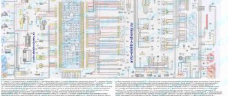
The outer number in the designation of the wire tip is the number of the block, the inner number is the conventional number of the tip.
K1 - Relay for turning on headlight cleaners; K2 - Relay interrupter for direction indicators and hazard warning lights; Short circuit - Windshield wiper relay; K4 - Relay for monitoring the health of lamps; K5 - Relay for turning on power windows (in a variant version of the car); K6 - Relay for turning on sound signals; K7 - Relay for turning on the heated rear window; K8 - Headlight high beam relay; K9 - Relay for low beam headlights; F1-F16 - Fuses
Electrical circuit diagrams for VAZ 21140, 21144, 211440, 2113, 2115 cars with a 1.5L (VAZ-2111 and VAZ 21114) and 1.6L (VAZ-11183) injection engine, as well as a 1.5L carburetor engine - VAZ-21083 (Samara 2; 199 7 -2013)
Source
How does a windshield wiper motor work?
Most cars have two blades that provide more effective cleaning of the windshield. A single wiper is usually mounted on the rear window.
The device operates in two or three modes, which allow the brushes to provide intermittent, slow or fast cleaning.
The overall design includes a wiper motor (a small motor with a gearbox), a brush return mechanism, a lever system and the cleaning rubber bands themselves. In parallel with the cleaner, you can use the windshield washer, which supplies water in the form of a directed jet.
One of the most unreliable elements of the system, which often fails, is the motor. If it breaks down, motorists do not know what to do and what the reasons may be.