On VAZ 21083, 21093, 21099 cars of the last years of production, the 9402.3701 generator was installed instead of the less powerful 37.3701.
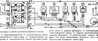
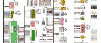
Connection diagram for generator 9402.3701 on VAZ 21083, 21093, 21099 cars with a carburetor or injection engine.
Instrument panel 2114, fuse mounting block 2114-3722010-10 or 2114-3722010-18
Notes and additions
— The fuse and relay mounting blocks 2114-3722010-10 and 2114-3722010-18 used on VAZ 21083, 21093, 21099 vehicles, unlike the mounting block 2114-3722010-60, do not have built-in resistors of the generator excitation winding circuit (battery charge indicator lamp) . On vehicles with these units, the resistor is built into the instrument panel (panel 2114).
More articles on generators for VAZ 2108, 2109, 21099 cars
A generator of type 94.3701 is installed on cars - alternating current, three-phase, with a built-in rectifier unit and an electronic voltage regulator, right rotation (on the drive side).
The generator rotor 94.3701 is driven by a poly-V belt from the engine crankshaft pulley (on some VAZ-2111 engines - from a damper).
Technical characteristics of the generator 94.3701
- Maximum output current at 13 V and 5000 min -1, A…..80
- Adjustable voltage limits, V…..13.2–14.7
- Engine-generator gear ratio…..1:2.4
- Capacitor capacity, µF…..2.2±20%
Generator 94.3701:
1 – casing; 2 – output “B+” for connecting consumers; 3 – noise suppression capacitor; 4 – common terminal of additional diodes (connected to the “D+” terminal of the voltage regulator); 5 – holder of positive diodes of the rectifier unit; 6 – holder of negative diodes of the rectifier unit; 7 – stator winding terminals; 8 – voltage regulator; 9 – brush holder; 10 – back cover; 11 – front cover; 12 – stator; 13 – stator winding; 14 – spacer ring; 15 – washer; 16 – conical washer; 17 – pulley; 18 – nut; 19 – rotor shaft; 20 – front rotor shaft bearing; 21 – beak-shaped pole pieces of the rotor; 22 – rotor winding; 23 – bushing; 24 – tension screw; 25 – rear rotor bearing; 26 – bearing sleeve; 27 – slip rings; 28 – negative diode; 29 – positive diode; 30 – additional diode; 31 – pin “D” (common pin of additional diodes).
Stator 12 (see figure above) and covers 10 and 11 are secured with four bolts. The rotor shaft 19 rotates in bearings 20 and 25, which are installed in the covers. The rear bearing of the generator is pressed onto the rotor shaft and pressed by the rear cover 10 through a plastic sleeve. The front bearing 20 is rolled into the front cover 11 and can only be replaced when assembled with it. The inner race of the front bearing 20, together with the spacer ring 14 and the washer, is clamped by a nut between the pulley and the rotor shaft. The rear part of the generator is covered with a plastic casing 1.
The generator stator is equipped with a three-phase winding 13, made in a star configuration (the phase windings have a common point), the other terminals of the phase windings are connected to a rectifier bridge consisting of six silicon diodes. The holders contain diodes of only one polarity. Holders 5 and 6 positive and negative diodes, respectively, form a rectifier unit, which is mounted on the rear cover 10 of the generator under a plastic casing 1. Three additional diodes 30 are installed on one of the holders, through which voltage is supplied to the excitation winding of the generator after starting the engine.
The field winding is located on the generator rotor. The excitation winding leads are soldered to two copper slip rings 27 mounted on the rotor shaft. Power is supplied to the field winding through two contact brushes and slip rings. The contact brushes are located in a brush holder 9, combined in one housing with a voltage regulator 8. The voltage regulator housing is non-separable; if it fails, it is replaced.
To protect the on-board network from voltage surges during operation of the engine control system and to reduce radio interference between the terminals of the positive and negative diodes, an interference suppression capacitor 3 with a capacity of (2.2 ± 0.004) μF, located on the rectifier unit, is connected.
The connection diagram for the 94.3701 generator system is shown in the figure:
Connection diagram for generator 94.3701:
1 – battery; 2 – generator; 3 – mounting block; 4 – battery charging indicator lamp, located in the instrument cluster; 5 – ignition switch (lock)
The current to excite the generator when the ignition is turned on is supplied to terminal “D+” of the regulator (terminal “D” of the generator) through indicator lamp 4 located in the instrument cluster. When the ignition is turned on, the lamp should be on; after starting the engine, it should go out if the generator is working. A bright or dimly lit lamp indicates a malfunction.
Warnings! The negative terminal of the battery should always be connected to ground, and the positive terminal to the B+ terminal of the generator. Failure to turn the battery back on will immediately cause increased current to flow through the alternator diodes, causing them to be damaged.
Do not operate the generator with the battery disconnected - this can damage the generator voltage regulator and the electronic devices of the vehicle's on-board network.
It is prohibited to check the functionality of the generator “for spark” even by briefly connecting the “B+” terminal of the generator to “ground”. Significant current will begin to flow through the valves and they will be damaged. The generator can only be checked using an ammeter and voltmeter.
It is not allowed to check the diodes of the generator rectifier unit with a voltage of more than 12 V or with a megger, since it has a voltage too high for the diodes and during testing they will be broken (a short circuit will occur).
It is prohibited to check the vehicle's electrical wiring with a megger or a lamp powered by a voltage of more than 12 V. If such a check is necessary, you must first disconnect the wires from the generator.
VAZ 2114 diagram
Detailed color diagrams of the VAZ 2114 wiring (carburetor, injector) are provided with a description of the electrical equipment for various modifications. The information is intended for self-repair of cars. Many electrical circuits are divided into several sections for ease of viewing via a computer or smartphone; there are also circuits in the form of one picture with a description of the elements - for printing on a printer.
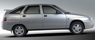
The VAZ 2114 (Samara-2) car is built on the VAZ 21093 platform and is an improved version of it. The first prototype of the hatchback was assembled back in 2000. A year later, the Volzhsky Automobile Plant produced the first pilot batch of 50 VAZ-2114 cars, and in the same 2001 the hatchback was first introduced to the market. The interior features a new instrument panel, a new steering wheel, an adjustable steering column, power windows and a new heater. Years of production 2114: 2001—2013
The fourteenth model was previously equipped with a 1.5 liter eight-valve engine, borrowed from the VAZ 2111 model with an injector. A little later it was replaced by the VAZ 11183-1000 version, which complies with the Euro-3 standard. The VAZ 2114 injector received a more powerful engine, and this is one of the reasons that the wiring of the 2114 has also changed.
A wiring harness has been added for connecting to the electronic switch. A harness has also appeared for connecting to the ignition module terminal.
Replacing high-voltage wires will require additional attention, because the connection procedure depends on the year of manufacture of the car. Until 2004, 4-pin ignition modules were installed, and after that - 3-pin. Connecting the adsorber valve to the injection system controller also provided another additional element. An adsorber is an electromechanical device used for ventilation and removal of condensate in a gas tank. Complications also affected the interior part. The dashboard received improvements in the form of the appearance of a BC (on-board computer), a new instrument panel and a change in the position of the glove compartment.
Generator repair for VAZ 2113-VAZ 2115
Disassembly
1) First you need to remove the generator; the article will help you understand the procedure: “Replacing the generator on a car.” Then remove the voltage regulator from the generator and the rectifier unit, the publication will help you with this: “Replacing the generator rectifier unit on a VAZ.”
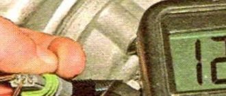
Note! The roller can be removed using an 8mm hex key. If you don't have one, try finding a flat-head screwdriver of the appropriate size. Be careful not to strip the thread when unscrewing the nut. The removal mechanism is as follows: a hex wrench stops the shaft with the installed roller from turning, and the roller fastening nut is unscrewed with a spanner (photo 1). Remove the unscrewed nut and its spring washer. By the way, this washer is of an unusual shape; examine it carefully: on one side it has a convex shape, and on the other it is flat. The convex part must be installed to the nut (photo 2).
2) We proceed directly to the repair. Use a marker or chalk to mark the two generator covers, noting their location relative to each other - you need to install them exactly as they were. Proceed to unscrewing the four bolts located around the circumference of the generator (photo 1). Next, use a flat-head screwdriver to separate both covers from each other (photo 2). Disconnect the cover located on the side of the slip rings (photo 3, rings are indicated by arrows). Now remove one of the important elements of the generator - the stator, by pulling it and removing it (photo 4).
Note! Be sure to check the removed stator for integrity; the condition should be acceptable, the inner surface (indicated by the arrow) without scratches - signs of touching the armature. The presence of marks and damage is a sign of faulty bearings or deformation of the generator cover.
3) Separate the cover from the rotor, and remove the rotor itself - simply grab the rotor with your hand and pull out the shaft (photo 1, the rotor shaft is indicated by a red arrow) from the bearing (indicated by a blue arrow). If the shaft does not pull out, screw the nut that previously secured the roller onto it. There is no need to install the roller, just screw on the nut. Then, having started to knock out the shaft, the rotor will not fly out of the bearing and will not hit the asphalt. Do not tighten the nut all the way, just screw it a little onto the thread. Using a hammer and a wooden spacer, knock the shaft with the rotor out of the bearing, controlling the effort. After removing the rotor, inspect the cover (photo 2). Pay special attention to the bearing; rotate it by hand: rotate the inner part in the direction where the rotor shaft was inserted. If you notice jamming, play, or rolling, replace the bearing. Take a screwdriver and remove the four screws securing the metal washer (photo 3), remove them from both sides of the cover. The bearing is knocked out using a hammer and a socket or mandrel of suitable diameter (photo 4).
Note! Check the cover for defects and if there is significant damage (large cracks, dents, etc.), replace the cover with a new one.
4) Let's move on to actually checking the generator. First, be sure to look at the contact rings (indicated by arrows in photo 1). The presence of marks, burrs, scratches is a sign that the rings need to be polished to a shine. This can be done using fine-grained sandpaper or a lathe. use the machine in extreme cases, for example, if nicks, marks and scratches cannot be removed with sandpaper. When working on the machine, erase the minimum layer of metal, and then sand it a little with sandpaper. Now take a multimeter and turn on the ohmmeter function on it. Check the resistance of the rotor winding by connecting the leads from the multimeter to the contact rings (photo 2). The infinity sign means that there is a break in the winding and the rotor must be replaced. Check whether the rotor winding is short-circuited to the housing: connect a multimeter to one of the rings, and throw the other lead onto the rotor housing (photo 3). The infinity sign in this case means that everything is in order and the winding does not short-circuit to the housing. Finally, check to see if the bearing on the ring side rotates easily (photo 4). The presence of play, wobbling, jamming during rotation, and rolling is a sign that the bearing is unsuitable for further use.
Note! Let's explain the bearing replacement procedure:
- be sure to stock up on a special bearing puller and press the bearing from the shaft (photo 1);
- install a new one;
- Find a mandrel (cap head) of a suitable diameter and hammer the bearing until it stops (photo 2).
By the way, try to choose a mandrel of such a diameter that it applies force only to the inner ring, indicated by the red arrow in photo 1).
Assembly
It is carried out in the reverse order of disassembly, taking into account some nuances:
- any bearing is pressed in with a hammer and a mandrel of the required diameter (photo 1)
- covers are carefully inspected for defects;
- the covers are connected relative to the previously made marks;
- an o-ring will be installed on one of the covers (photo 2), which must be replaced in case of defects (cracks, breaks).
Note! Install the adjustment washer located between the generator roller mounting nut and the cover bearing with its convex side facing the nut and tighten it to a torque of 39–62 N·m (3.9–6.2 kgf·m) using a torque wrench.
Car modifications 2114
VAZ-21140 . Modification with an 8-valve injection engine VAZ-2111, 1.5 liters and 77 horsepower. Serial production from 2003 to 2007
VAZ-21144 . Modification with an 8-valve VAZ-21114 engine, 1.6 liters and 81.6 horsepower. Years of serial production: 2007-2013.
VAZ-211440 . Another modification released in 2007, it was equipped with a VAZ-11183 engine with a volume of 1.6 liters and a power of 82 horsepower. The car was discontinued in 2013.
VAZ-211440-24 . Released in 2009, a modification with an injection 16-valve VAZ-21124 engine with a volume of 1.6 liters and a power of 89.1 horsepower. Discontinued in 2013.
VAZ-211440-26 . Modification with a 16-valve injection engine VAZ-21126, which complies with the Euro-3 environmental standard, with a volume of 1.6 liters and a power of 98 hp. The car was produced from 2010 to 2013.
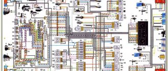
Wiring diagram VAZ-2114 for old models
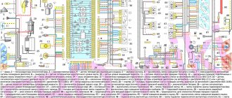
Electrical diagram of car 2114: 1 - headlight; 2 [Installed on a part of the car] - fog lamp; 3 — ambient air temperature sensor; 4 — electric engine radiator fan; 5 — block for connection to the wiring harness of the engine control system; 6 — engine compartment lamp switch; 7 [Installed on a part of the car] - reserve block for connecting an audio signal with one terminal (the negative terminal is connected to the body); 8 — sound signal; 9 — liquid level sensor in the windshield washer reservoir; 10 [Installed on a part of the car] - brake pad wear sensor; 11 — low oil level sensor; 12 - generator; 13 [Installed on a part of the car] - engine compartment lamp; 14 — temperature indicator sensor; 15 — starter; 16 — battery; 17 [Installed on a part of the car] - relay for turning on fog lights; 18 — coolant level sensor in the expansion tank; 19 — sensor of insufficient brake fluid level; 20 — reversing light switch; 21 — windshield wiper gear motor; 22 — emergency oil pressure sensor; 23 — rear window washer electric pump; 24 — electric pump for windshield washer; 25 — instrument panel; 26 — mounting block of fuses and relays; 27 — brake signal switch; 28 — ignition relay; 29 - ignition switch (lock); 30 — glove box lighting lamp; 31 — switch for the glove compartment lighting lamp; 32 — rear window heating switch; 33 — rear fog light switch; 34 [Installed on a part of the car] - fog light switch; 35 - combined switch for side lights and headlights; 36 — alarm switch; 37 — steering column switches; 38 — brightness control for instrument lighting; 39 — illumination lamp for the headlight hydraulic adjustment control handle; 40 — socket for connecting a portable lamp; 41 — side direction indicator; 42 — interior lighting switch (front door open sensor); 43 — interior lamp; 44 — electric fan of the ventilation and heating system; 45 — additional resistor of the electric fan of the ventilation and heating system; 46 — switch for operating modes of the electric fan of the ventilation and heating system; 47 — illumination lamp for the handle of the operating mode switch of the electric fan of the ventilation and heating system; 48 — backlight lamp for the heater control unit; 49 — display unit of the on-board control system; 50 [Installed on part of the car] - trip computer; 51 — interior lighting switch (rear door open sensor); 52 [Installed on a part of the car] - block for connecting a clock; 53 — fuel module; 54 — ashtray illumination lamp; 55 — cigarette lighter; 56 — interior lamp; 57 — switch for the parking brake warning lamp; 58 — rear light; 59 — license plate light; 60 — additional brake light; 61 — heating element for heating the rear window; 62 — rear window wiper gear motor; A - numbers of pins in connecting blocks.
Checking the generator and choosing a new one
Generator failure causes some side effects that may signal it. The main signs of a node malfunction are :
- constant “glow” of the battery charging indicator;
Battery charging indicator stays on
The easiest way to check the functionality of the generator is to measure the voltage supplied to the battery terminals with a multimeter. If it deviates from the norm, then there are clearly problems. More complex diagnostic measures involve dismantling the part and checking the operation of each component separately, with the possibility of partially repairing the part. This type of diagnosis and repair can only be successfully carried out by a professional electrician.
Check the voltage at the battery terminals with a multimeter while the engine is running.
In the event that the need for replacement is confirmed or there is a desire to perform it due to some other purpose, first of all, it is necessary to select a new generator set. According to drivers and auto experts, the best generators for the VAZ-2114 are :
- any generating set from Lada: Priora and Kalina, equipped with air conditioning, its power is 115 A;
- identical factory generator set from the manufacturer Eldix;
- generators from PRAMO, the most successful option would be to choose a unit with a power of 120 A.
Important! Too cheap installations often fail much faster than their more expensive counterparts, so it’s better not to skimp when purchasing.
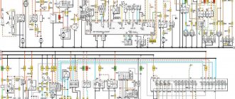
VAZ-2114 diagram (second option)
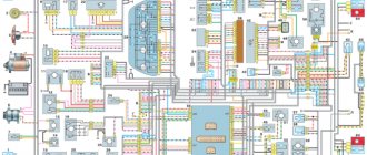
Electrical diagram of VAZ-2114 cars (without engine control system):
1 — block headlights; 2 — fog lights; 3 — air temperature sensor; 4 — electric motor of the engine cooling system fan; 5 — blocks connected to the wiring harness of the ignition system; 6 — engine compartment lamp switch; 7 — block for connecting to a single-wire type audio signal; 8 — sound signal; 9 — washer fluid level sensor; 10 — front brake pad wear sensor; 11 — oil level sensor; 12 - generator; 13 — engine compartment lamp; 14 — coolant temperature indicator sensor; 15 — starter; 16 - battery; 17 — relay for turning on fog lights; 18 — coolant level sensor; 19 — brake fluid level sensor; 20 — reverse light switch; 21 — windshield wiper gearmotor; 22 — oil pressure warning lamp sensor; 23 — block for connecting to the rear window washer electric motor; 24 — electric motor for windshield washer; 25 — instrument cluster; 26 — mounting block 2114; 27 — brake light switch; 28 — ignition relay; 29 — ignition switch; 30 — glove box lighting lamp; 31 — glove box lighting switch; 32 — rear window heating element switch; 33 — rear fog light switch; 34 — fog lamp switch; 35 — switch for external lighting lamps; 36 — alarm switch; 37 — steering column switches; 38 — switch for instrument lighting lamps; 39 — lamp for illuminating the headlight hydrocorrector scale; 40 — plug socket for a portable lamp; 41 — side direction indicators; 42 — lamp switch on the front door pillars; 43 — lamp for individual interior lighting; 44 — heater fan electric motor; 45 — additional resistor of the heater electric motor; 46 — heater fan switch; 47 — heater switch illumination lamp; 48 — lamp for illuminating the heater levers; 49 — on-board control system unit; 50 — trip computer; 51 — lamp switch on the rear door pillars; 52 — block for connecting the wiring harness of the engine control system; 53 — electric fuel pump and gasoline quantity sensor; 54 — front ashtray illumination lamp; 55 — cigarette lighter 2114; 56 — trunk lighting lamp; 57 — trunk light switch; 58 — interior lamp; 59 — parking brake warning lamp switch; 60 — rear external lights; 61 — rear internal lights; 62 — block for connection to the rear window heating element; 63 — license plate lights; 64 - additional brake signal located in the spoiler.
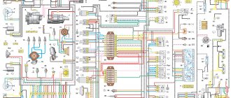
Wiring diagram VAZ-2114 new models
The updated engine has a new injection scheme, so it was necessary to use some new devices, as well as replace the ignition coil with a more efficient one and adapted to Euro 3 conditions. In order to comply with them, the engine had to minimize the amount of CO at start-up. And for this it was necessary to lean the mixture. Since a lean mixture ignites worse, it needed a more powerful spark to spark. This explains the use of a coil of increased power.
- block headlights;
- gearmotors for headlight cleaners*;
- fog lights*;
- ambient temperature sensor;
- sound signals;
- engine compartment light switch;
- engine cooling fan electric motor;
- generator VAZ-2114;
- low oil level indicator sensor;
- washer fluid level sensor;
- front brake pad wear sensor;
- wire ends connected to the common windshield washer pump**;
- windshield washer pump;
- headlight washer pump*;
- wire ends for connecting to the rear window washer pump on VAZ-2113 and VAZ-2114 cars;
- low oil pressure indicator sensor;
- engine compartment lamp;
- wire lug for connecting to the engine management system wiring harness;
- windshield wiper gear motor;
- starter VAZ-2114;
- block connected to the wiring harness of the ignition system on carburetor cars;
- coolant temperature indicator sensor;
- reverse light switch;
- low brake fluid level indicator sensor;
- accumulator battery;
- low coolant level indicator sensor;
- relay for turning on fog lights;
- mounting block;
- brake light switch;
- plug socket for a portable lamp;
- hydrocorrector scale illumination lamp;
- parking brake indicator lamp switch;
- block for connecting a backlight lamp;
- switch for instrument lighting lamps;
- Understeering's shifter;
- hazard switch;
- front seat heating element relay;
- ignition switch;
- rear fog lamp circuit fuse;
- front seat heating elements circuit fuse;
- door lock circuit fuse;
- front ashtray illumination lamp;
- ignition relay;
- cigarette lighter VAZ-2114;
- glove box lighting lamp;
- glove compartment light switch;
- heater fan motor;
- additional heater motor resistor;
- heater fan switch;
- heater switch illumination lamp;
- heater lever illumination lamp;
- gear motors for electric windows of the front doors;
- right front door ESP switch (located in the right door);
- gear motors for locking front door locks;
- wires for connecting to the right front speaker;
- gear motors for locking rear doors;
- wires for connecting to the right rear speaker;
- door lock control unit;
- wires for connecting to radio equipment;
- headlight wiper switch*;
- rear window heating element switch;
- rear fog light relay;
- block for connection to the heating element of the right front seat;
- rear fog light switch;
- right front seat heating element switch;
- fog light switch*;
- switch for external lighting lamps;
- left front seat heating element switch;
- block for connection to the heating element of the left front seat;
- wires for connecting to the left front speaker;
- left front door power window switch (located in the left door);
- right front door power window switch (located in the left door);
- wires for connecting to the left rear speaker;
- side direction indicators;
- dome light switches on the front door pillars;
- dome light switches on the rear door pillars;
- lampshade VAZ 2114;
- individual interior lighting lamp;
- block for connecting to the wiring harness of the electric fuel pump;
- trunk light switch;
- instrument cluster;
- trunk light;
- on-board control system display unit;
- trip computer*;
- block for connecting the wiring harness of the engine management system;
- rear exterior lights;
- rear interior lights;
- pads for connecting to the rear window heating element;
- license plate lights;
- additional brake signal located on the spoiler.
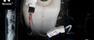
Where is the generator located?
Engine VAZ 2114
How to change brushes on a VAZ 2114 generator? Before answering this question, let’s determine where the patient himself is. This is the simplest, but at the same time difficult question, because the generator is under the hood. But when you open it, the alternator is not visible there, because it is attached to the bottom of the engine and connected to the crankshaft by a separate belt. To see it, you need to be in front of the car and look into the left side of the hood behind the engine. There you will also find a belt tensioner.
To easily replace the brushes, it is necessary to dismantle the generator, because this will allow you to check it more thoroughly as a whole. But if desired, this can be done without removing it. But then a number of problems arise that are associated with limited space and the inability to support anything with the second hand if necessary. In addition, you must be 100% sure that the problem is only in the brushes.
Removing the generator
Before starting to work with the elements and devices of a machine powered by electricity, it is necessary to disconnect the negative terminal from the battery.
In order to remove the generator, you need to loosen the tension bolt or mechanism and move the generator towards the engine with a pry bar or a large screwdriver. After which the belt can be easily removed. Next, you should loosen the mounting bolt with a head of 17. And freely remove the generator. Of course, before removing the generator, it is necessary to disconnect all terminals and wires from it.
Replacing brushes
Generator brushes VAZ 2114
Replacing brushes on a VAZ 2114 consists of the following sequence of actions:
- disconnect the negative terminal from the battery;
- disconnect the block with wires and the protective rubber cap;
- unscrew the clamping nut and remove the power wires from the stud;
- release three latches around the perimeter of the round plastic cover;
- remove the cover and find the regulator with brushes in the water body;
- unscrew the mounting bolts of the brush device;
- remove the brushes with the regulator;
- take new brushes and measure the size of the protruding graphite contacts, it should be at least 1 cm;
- if the size corresponds to the required one, then it is necessary to check the regulator itself;
- take new brushes and perform all the steps in reverse order.
The steps to remove the generator when replacing the brushes will be the same, but you have the need to carry out a complete diagnosis of it.
After replacing and installing the generator in place, it is necessary to check the belt tension. It should be no more than 10 kg. This can be checked using a special device or by eye. The belt should sag slightly when pressed with a hard object, but should not be taut like a string.
Relays and fuses VAZ 2114
F1 for 10 Amps (A) rear fog lights and rear fog light warning lamp. F2 for 10 A turn signal lamps, turn signal relay, hazard lights, hazard warning lights. F3 7.5 A lamps for interior lighting (both) and trunk, ignition lighting, powertrain control system control lamp, brake lamps, computer, if available. F4 20 A carrier, relay and rear window heating element. F5 20 A horn and its relay, cooling fan. F6 30 A power windows and their relays F7 30 A motor heater, headlight cleaner, windshield washer, cigarette lighter, glove compartment light bulb, rear window heating relay winding. F8 7.5 A right fog lamp. F9 7.5 A left fog lamp. F10 at 7.5 A left side marker, lamp signaling the inclusion of the side light, lamps for illuminating the sign, engine compartment, illumination of switches and instruments, instrument lighting switch. F11 at 7.5 A right side. F12 at 7.5 A right low beam. F13 at 7.5 A left low beam. F14 for 7.5 A left high beam and a light indicating that the high beam headlights are on. F15 at 7.5 A right far. F16 30 A - a light indicating insufficient oil pressure, brake fluid level, engagement of the parking brake, low battery, instrument cluster, relay for monitoring the health of lamps, indication of control systems, reversing lamps, turn indicators and their relays, as well as an alarm if turning mode is turned on, computer, generator excitation winding is turned on at the moment the engine starts.
Main reasons
The charging indicator informs the driver about its operation. If the circuit is working properly, it lights up when the ignition is turned on and goes out when the engine is running, since the voltage at terminal D and the battery become approximately equal.
Damage to every part of the circuit is the reason why the battery does not charge. The defect can be either electrical or mechanical. For example:
- oxidation, poor contact of the positive wire terminal between the battery and the generator;
- in electrical wiring - breakage, damage to insulation;
- generator malfunction;
- belt wear - broken or stretched;
- battery problems;
- a light bulb, fuse or poor (oxidized) contact has burned out;
To restore normal operation of the circuit, these elements should be checked.