01/26/2022 14,281 VAZ 2114
Author: Ivan Baranov
While operating a car, some car enthusiasts are faced with the same important question, namely: how to remove the box on a VAZ 2114 or on another car of this AvtoVAZ line. The VAZ 2114 gearbox is the same as on the VAZ G8. The only difference is that the VAZ 2108 does not have a dipstick, and it accelerates faster.
The gearbox may need to be removed in a variety of cases, for example, in order to replace the clutch or something in its system, as well as to repair the gearbox itself.
[Hide]
We remove the VAZ 2114 gearbox
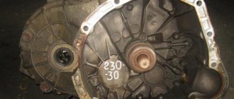
Many car owners have a question about how to remove the VAZ 2114 gearbox in order to repair or tune the transmission with their own hands. The design of this unit is common to all cars of the Lada Samara family: the gearbox is mechanical, 5-speed, combined with a differential and final drive.
The input shaft gears are in mesh with the secondary gears of the forward gears. Driven gears are installed on the secondary shaft. Each of those that includes forward gears has a synchronizer. But there is no synchronizer on the reverse gear. The gearbox drive includes a selector rod and gear shift lever, a ball joint and gear mechanisms.
Repair of the VAZ gearbox may be required if, when changing gears, there is a crunching or grinding noise in the gearbox, it hums, moving the lever causes difficulties, some gears switch off spontaneously (the synchronizer is damaged or the drive is incorrectly adjusted). The gearbox is removed if the vehicle's clutch is subject to repair.
What is differential preload
Repair, operation and installation of VAZ 2113, 2114, 2115
cars The car differential distributes torque from the drive shaft to the right and left axle shafts. The differential consists of 4 bevel gears. Not big in size. If the wheels rotate with the same load, then the differential distributes the rotation force in half (50:50).
If one wheel hits, for example, ice, then the differential provides more rotational force to one wheel and less to the other. The wheel that is on the ice receives an increased angular speed and will become the driving wheel, and the wheel that is spinning on the asphalt will no longer receive rotational speed and will become the driven wheel. Because of this, the fact that the torque is transmitted to only one wheel, and to the one that is (in this case) on the ice, the control and maneuverability of the car is greatly deteriorated. But, in order to maintain controllability and cross-country ability, the leading wheel had to be the wheel that is on the asphalt. To avoid such an unnecessary effect, a device was invented - an automatic limited slip differential.
Self-locking differentials
The limited friction mechanism is a multi-disc differential, a viscous coupling, a Quaif and Thorsen self-locking differential that performs partial locking automatically, without the driver switching the handle.
The difference between an automatic differential and a symmetrical one is that an automatic self-locking one has a spring pack of friction discs.
The auto differential consists of:
- driven worm (semi-axial) gears;
- driving worm (satellite) gears.
The axes of the satellites and semi-axes are parallel to each other. If one wheel, say the right one, begins to rotate slower than the wheel opposite, then, accordingly, the axle shaft with gear rotates more slowly and rotates satellite 2 at the same angular speed. Satellite 2 transmits rotation to satellite 3. Satellite 3 transmits rotation to the gear of axle 4. The result is different angular speeds of the wheels when turning.
Due to the fact that the torques in the screw engagement are different, axial and radial forces appear that press gears 1 and 4, satellites 2 and 3 with their ends to the differential cover. Worm satellites 2 and 3 are pressed against the surfaces of the holes in which they sit. Thanks to the forces generated in this case, the axle shafts are blocked. How much the axle shaft will lock is determined by the locking coefficient.
Characteristics of the self-locking differential:
- differential locking coefficient in % (CBD) (depends on the inclination of the teeth, if helical, or, if it is a disc, then the angle of the cup);
- locking preload in kg (this is the static resistance between the 2 axle shafts).
CBR is the ratio of the moments of force of the lagging behind to the advancing, that is, the torque of the lagging wheel is divided by the torque of the wheel that rotates faster.
Advantages of a limited slip differential:
- The driver does not need to engage the self-locking differential himself; everything happens automatically.
- Eliminates slipping at different wheel traction values.
- Improves cross-country ability and driving dynamics of vehicles on different roads.
- Acceleration efficiency increases on different road surfaces.
- Parts of self-locking and conventional differentials are interchangeable.
- Any axle shaft will not break because the wheels are not completely locked.
- Disabling, that is, unlocking is carried out by releasing the gas pedal.
Self-locking helical differentials are effective for a regular car. Such devices are reliable. The working service life of screw self-blocks is the same as that of gearboxes (gearboxes). They are smoothly activated and deactivated.
Failures that do not require removal of the gearbox
If the reverse gear does not engage, then it is not necessary to remove the box: it does not have a synchronizer installed, the problem can be solved more simply. Before making a decision, you need to check the universal joint and the linkage, as the problem may be caused by a loose clamp. Another reason could be that the mechanism is blocked.
To check, remove the lever between the seats and visually assess whether there is a problem. The same operation must be performed if there is a crunching sound when engaging 2nd gear, since the most likely cause of the malfunction may be a worn synchronizer, which in the Lada Samara family of cars is not very durable.
Do I need to remove the gearbox if the gearshift lever rattles? This question worries many, but most often, removing the gearbox will not be necessary to fix the problem. An unpleasant sound occurs when the bushing that connects the rod and rod touches the wings of the latter. The metal bushing rattles due to frequent impacts on the metal of the wings. The defect of the VAZ 2114 manufacturer can be easily eliminated with your own hands.
According to reviews from car owners, this simple step eliminates the rattling of the gearshift lever. Handle vibration disappears. It will move stiffly, but it will gradually loosen and work easier.
Preparatory work
Before starting work, the car should be placed on an inspection ditch or driven onto an overpass and make sure that the raised hood is secured and the car is on the handbrake. During work, the engine will need to be suspended.
Therefore, you should provide the opportunity to install a hoist or use improvised means, a special device (crossbar to support the engine). To repair a VAZ 2114 gearbox, you need the following tools:
Transmission device: 1 - input shaft; 2 - secondary shaft; 3 — rod for shifting the third and fourth gears; 4 — fork for shifting third and fourth gears; 5 — differential; 6 — fork for switching first and second gears; 7 — fork rod for shifting first and second gears; 8 — gear shift rod; 9 — fifth gear shift fork rod; 10 — gear shift mechanism; 11 — reverse intermediate gear; 12 — clutch housing
It is more convenient to carry out work on removing the VAZ 2114 gearbox together with an assistant. First you need to disconnect the battery and put it aside. Drain the oil from the gearbox, having previously warmed it up, to do this, drive about 5 km before repairing.
With the car installed on the overpass, unscrew the 3 bolts securing the crankcase protection and remove it, remove the dipstick to check the oil level (in models produced earlier than 2003) or unscrew the oil filler plug. Place a container under the oil drain hole, use a 17mm wrench to unscrew the plug and wait until the oil is completely removed from the gearbox.
Remove the engine starter by sequentially disconnecting the column of wires, unscrewing the fastening nut and removing the wire on the contact bolt of the starter relay under the hood of the car. Go down under the bottom and remove the unit fastenings, then unscrew the last fastening again under the hood. Remove the starter from below.
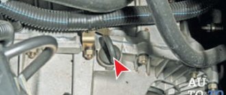
Disconnect the speed sensor wires under the hood by compressing the spring holding the block. Disconnect the reverse sensor wires from below. Under the hood, unscrew bolts 1-3 connecting the gearbox housing and the ignition module bracket. Disconnect the torque rod bracket, loosen the gear shift rod clamp and remove the speed selector rod hinge rod.
To do this, you need to move it back a little. Remove the left front wheel drive and install a plug in its place. It is enough to disconnect the right wheel drive from the box and move it to the side, securing it in this position. Remove the left ball joint bolts that secure it to the steering knuckle.
How the box works
It has features that entirely depend on the configuration of the machine. This could be a four- or five-stage vase model. The structure of a four-speed gearbox is as follows:
- 1. Primary shaft;
- 2. Reverse gears, to which the front shaft is attached;
- 3. Synchronizers, 2 pieces;
- 4. Bearings placed on the secondary shaft;
- 5. Driven gear. Attached to the differential flange.
The element is controlled by a drive, rod, rod and ball joint. Only complete interaction of these parts can ensure full operation of the box.
Gearbox device
To determine the type of gear, there is an additional lever, which is attached to the inner end of the rod.
There are also axles in the body; a three-arm lever is attached to one of them. Its main purpose is to lock the bracket and bushing, which is necessary to ensure the strength and immobility of the mechanism.
The second axis is designed to fix the locking brackets from their rotation, passing through the center. In addition, there is a lock that prevents the box from loosening. The other axle also has a fork, which is necessary to engage the VAZ 2114 in reverse.
The five-stage type differs in the size of the shaft and the absence of a bushing in the element. Usually this is what is installed in the VAZ 2114, since the other one is not entirely practical to use. Like any spare part, a gearbox can also break down and fail.
The most common problems are:
Unknown noise: it may be caused by bearing failure or gear wear. In addition, you should play it safe and check the oil level;
The solution to the problem is to completely replace failed spare parts and add oil.
Difficulty shifting the VAZ 2115 gearbox: the drive rod may have become deformed. It would be a good idea to check how firmly all the screws are screwed on and how the box drive is adjusted correctly. There is a possibility of failure of plastic parts in the drive;
Solution: Strengthen the screws, adjust the drive, replace worn and failed parts, replace or correct the deformation of the rod.
Turning off the gearbox without the driver's participation: the cause may be damage to the teeth on the synchronizer, an incorrectly adjusted drive, or poor installation of the traction cover, which provokes incomplete engagement of the traction;
Solution: Adjust the drive and replace the covers, replace the failed spare parts.
Oil leak. The reason is still the same - wear of spare parts, which this time are oil seals, seals and hinge bodies
In addition, you need to pay attention to the strength of the fastening. If it becomes loose, it is necessary to tighten all the bolts and check the seals for damage;. Solution: Purchase new spare parts and replace them
Solution: Purchase new spare parts and replace them.
Where and how is it more profitable to buy a gearbox in case of its complete failure? Since the performance of the vehicle and safety depend on the VAZ 2114 gearbox, its technical condition must be taken very seriously.
That is why it is worth recalling that, like any element of the machine, the gearbox needs regular technical inspection. Saving on oil changes, untimely detection and replacement of breakdowns, complete ignorance of troubles with the machine’s mechanisms - all this leads to failure of the gearbox.
Don’t think that if you have a domestic car, that means you are lucky. The rise in prices for spare parts is indicated by the price of the box, which today ranges from 16 thousand rubles. up to 18 thousand rubles Add in fees for removal, installation and maintenance - the cost will be impressive.
Used manual transmission for Lada 2114
An easier option would be to purchase a used item. No one will give a guarantee that there are no defects in it, but the purchase will cost half as much.
The best option is to carry out timely maintenance and repair of the box. This approach will not only save the budget, but will extend the life of the parts.
How to remove a VAZ 2114 gearbox, its repair and malfunctions
In domestic VAZ cars, almost any repair can be done with your own hands if you have the appropriate skills and experience. But if even a novice car enthusiast can change disks, then to service and replace power plant parts you need to know your car 100%. The VAZ 2114 gearbox is a complex unit with a lot of parts and fasteners that you will have to tinker with. Before work, you should familiarize yourself with the device: the gearbox diagram is present in the operation and maintenance manual for the Lada Samara.
Removing the gearbox may be necessary in the following cases:
The design of the gearbox, as well as other mechanisms, is common to the entire Lada Samara model range. The VAZ 2114 engine is paired with a 5-speed manual transmission. As for the features of the mechanism, these include the adjacent operation of the main gear and differential.
Are adjustments done differently on different brands of cars?
The above procedures are universal and can be performed on machines from any manufacturer. The essence of the procedure is always the same - to reduce or increase the pedal stroke by tensioning or loosening the cable, or adjusting the hydraulic pusher.
But when adjusting the clutch in cars of different brands, there may be some differences. For example:
- normal pedal amplitude or clutch clearance;
- procedure for accessing the clutch adjusting and control nuts. So, in a VAZ-2114, 2115 you will have to remove the battery before starting work, and in a Lada Kalina you will have to unscrew the air filter.
Before starting work on adjusting the clutch, read the technical information about your vehicle, the operating instructions and the repair manual. This will allow you to complete the procedure correctly.
Transmission malfunctions
First, it is worth considering faults that can be removed without dismantling. If the reverse gear does not press, it is worth checking the clamp and the mechanism itself for blocking. Another common problem is a rattling gearshift lever. The sound comes from a bushing that hits the surface of the wings. You can solve a manufacturing defect using a file - the error is determined and excess metal is removed.
It is recommended that you carry out the removal repairs together with a friend. During work, there will be times when you need to unscrew the fasteners both under the hood and in the interior of the VAZ 2114. It is also more convenient to check with an assistant whether the gearbox was installed correctly.
Repair and, accordingly, removal of the gearbox is required when, when changing gears, a grinding or crunching sound appears in the gearbox, a hum is heard, and the lever moves with difficulty. Also, dismantling is indispensable when some gears are switched off randomly (the problem is caused by a drive adjustment failure or a synchronizer failure).
Differential purpose
When turning a car, wheels located closer to the center of curvature of the trajectory travel a shorter distance than those rotating in an outer arc. Their speeds are also different. And since a drive without a differential rotates both wheels of the same axle at the same speed, one of them begins to slip. This increases tread wear and worsens vehicle handling. The differential allows the drive wheels to rotate at different speeds.
As long as the drive axle is in good contact with the road, this device works flawlessly. But as soon as the road grip under one of the wheels deteriorates, for example, when it hits ice or liquid mud, only one of them will rotate. A wheel with a high coefficient of adhesion stops spinning and the car stops. If you lock the differential, this will not happen. Therefore, a locked differential improves the vehicle's maneuverability on difficult sections of the road.
Device
The operating principle of the above-mentioned unit is the same, no matter where it is installed. The classic car differential is based on a planetary gear. The cardan shaft rotates the drive gear of the axle reducer. Its rotation is transmitted to the driven gear. And since it is attached to the differential housing, it moves with it. From the body, the torque is transmitted to the axle shafts using gears independent from each other, called satellites. The rotation speed of the propeller shaft is not equally divided between the axle shafts. However, for any ratio of speeds, their sum is always constant.
- automatic;
- forced, activated by the driver.
By blocking control method:
- mechanical;
- electromechanical;
- hydraulic;
- pneumatic
Automatic differential lock
A self-locking differential is a mechanism that, under certain conditions, switches and, turning into a direct transmission, begins to divide the rotation speed of the driveshaft between the axle shafts equally. Differentials with automatic locking can lock themselves depending on the value of one of two parameters:
- differences in angular velocities of the axle shafts. This group includes differentials with disc locking, cam, viscous coupling and operating according to the Ferguson formula;
- torque transmitted to the axle shafts.
Removing the gearbox
If all the steps described above have been completed correctly, then withdrawal can begin. The process goes as follows:
Unscrew the gearbox bolts
We hang up the gearbox and remove it
When the work is completed and the box is completely dismantled, you should disassemble it and check the parts for wear. If possible, repairs and replacement of damaged elements are carried out. In some cases, the problem can be solved by replacing bearings or seals, rather than purchasing a new gearbox.
Source
Preparing for removal
Preparatory work includes the removal of all parts that block access to the gearbox. You can begin removal when you have a board or other hanging equipment, a set of wrenches and sockets, different types of screwdrivers, and WD-40 lubricant at hand. It is also recommended to carry out work in a garage where there is a car pit. Now you can proceed to the analysis:
- It is necessary to remove the terminals from the battery and then remove it. The next step is to completely remove the working fluid from the gearbox and remove the starter. Some bolts may not budge, in which case WD-40 must be used;
- Now the VAZ 2114 needs to be placed on the pit and the crankcase protection, which is attached to the bottom with three fasteners, removed;
- There is a cable coming from the clutch fork - it should be disconnected from the fork and then removed from the gearbox bracket;
- Next, you need to hang the motor to gain access to the lower parts. After this, all wires must be disconnected from the speed sensor. A spring is used as fastening here.
Gearbox (gearbox) for VAZ 2114 - repair, disassembly and assembly of gearbox
Symptoms of a malfunction on a VAZ 2114 gearbox include problems when turning on the speed. As practice shows, the main source of these problems is the VAZ 2114 gearbox: malfunctions in its mechanism (the VAZ 2114 gearbox rattles, or the VAZ 2114 gearbox rattles, the VAZ 2114 gearbox rattles, the VAZ 2114 gearbox leaks). Repair of the VAZ 2114 gearbox, disassembly and assembly of the gearbox is carried out by auto mechanics. But if you have knowledge and experience in driving a VAZ 2114, you can repair the gearbox yourself.
Repair of VAZ 2114 gearbox
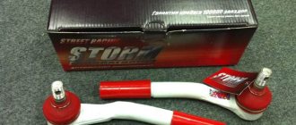
According to the source of this article, provaz2114.ru, the most reliable method of keeping the mechanism in good condition is prevention of malfunctions (systematic maintenance) and proper operation. But even so, situations are possible that require prompt repairs. When the gearbox cannot be repaired, information becomes relevant about how much a new VAZ 2114 gearbox costs? Estimated price in stores is 16 thousand rubles, used: 4000-10000 rubles. When the gear knob is loose on a VAZ 2114, it is possible that the solution to the problem is to install a new one. The VAZ 2114 gearbox linkage also needs to be replaced.
General symptoms
Symptoms are manifested by seven signs, which include:
Each of the listed symptoms has its own etymology and an exact picture of its manifestation, which objectively characterizes the root cause of the malfunction.
Crunch in the gearbox
This type of repair requires disassembling the gearbox structure.
The main reasons, a sign of which is a crunching noise during gear shifting:
Knocking at the checkpoint
The sounds of gearbox tapping are ambiguous due to their multiplicity. Therefore, the picture of the malfunction is accurately established by diagnosing the vehicle.
The box starts knocking if:
Oil leakage
If there is an oil leak, the repair task is facilitated by the ability to determine the location of the leak, but most often in practice this is impossible to determine.
Faults that cause oil leakage are the following:
Speeds are flying out
This kind of phenomenon occurs during gear shifting. The main reason for the appearance of such a malfunction is wear of the teeth on the gears and coupling. A factor contributing to the development of weakening speed control is a violation of the rules of gear shifting technique, which occurs when the speed limit is not observed. Replacing the gears of the specified parts eliminates the described problem.
The handle is tight
Factors under the influence of which the movement of the handle is difficult are damage to the locking teeth of the lever itself, wear of the jet thrust, and violation of the integrity of the gearbox drive parts.
The box is humming
This sound appears mainly during neutral transmission. The main reason is the low quality of lubricants. Therefore, the first action that must be performed when this type of technical problem occurs is to check and, if necessary, add oil. If the box continues to hum, then it is necessary to perform diagnostics, since the bearing on the input shaft may be worn out.
Noise in the CP
The box begins to make noise when the oil level is insufficient. This situation can be resolved by adding oil. If the noise does not stop, then it is caused by wear of the seals and mechanisms. This can be eliminated by installing new parts to replace worn ones.
Upon completion of the process of identifying the malfunction, its cause and source, as well as the factors influencing the occurrence of malfunction of the gearbox, it is necessary to become familiar with its structure and the structural features of the mechanism.
Malfunctions and reasons for their occurrence
Resetting gears (shifting does not result in a gear change)
Speed slippage is a sign of worn gears and couplings. Most often this is due to a violation of the gear shift order or incorrect position of the traction protective cover.
Sticking (stiff movement) of the shift lever
The malfunction may be caused by wear of the plastic parts of the drive, reaction rod, or damage to the hinge teeth of the lever fixation.
Oil leaks
If you can find the source of the leak visually, it is better to eliminate the cause immediately. The cause of leaks, when the source of the leak could not be detected, may be worn shafts and seals, depressurization, damage to the seal, or play in the box shaft.
Rumble
The hum usually occurs in neutral gear. Most often it is associated with a lack of oil in the unit or its poor quality. If the oil level is normal, the problem is most often a worn front shaft bearing.
Crunch
If a crunching noise occurs, the synchronizers should be replaced as soon as possible. If this is not done in time, the gear unit will completely fail. The condition of the clutch basket, in which the teeth “fly out” over time, can also cause crunching.
Transmission device diagram
The gearbox mechanism is a system of parts that has an independent structure and characteristic features determined by the model. Before you begin repairing the gearbox, you must familiarize yourself with the diagram of the transmission mechanism in the operating manual. The diagram contains the names of the parts and the structure of the relationship.
Transmission device: 1 - input shaft; 2 - secondary shaft; 3 — rod for shifting the third and fourth gears; 4 — fork for shifting third and fourth gears; 5 — differential; 6 — fork for switching first and second gears; 7 — fork rod for shifting first and second gears; 8 — gear shift rod; 9 — fifth gear shift fork rod; 10 — gear shift mechanism; 11 — reverse intermediate gear; 12 — clutch housing
Knowledge of the structure of the structure reduces the time spent on identifying mounting fasteners and dismantling components.
Gear shift mechanism
The gearshift mechanism is usually mounted in gearbox covers and is used to select, engage, and disengage gears. In addition, devices are installed in the gear shift mechanism that prevent the inclusion of two gears at the same time and prevent spontaneous gear shifting.
The main requirements for this mechanism are ease and simplicity of gearbox control, noiseless and smooth gear shifting, reliable locking of the engaged gear, prevention of simultaneous engagement of two or more gears, as well as protection from engaging a gear opposite to the vehicle's movement while moving. In addition, the activation mechanism must be reliable, durable, not requiring complex adjustments and easy to maintain. Malfunctions of the gear shift mechanism can lead to damage to parts and failure of such an expensive unit as a gearbox.
***
The gearbox shift mechanism of a truck (Fig. 1, a) consists of three rods, three forks, three clamps with balls, a fuse for engaging first gear and reverse gear and a locking device. Rods 8, 9, 11 are located in the holes of the internal bosses of the crankcase cover 1. Forks 5, 7, 10 are attached to them, connected to the synchronizer carriages and to the movable gear wheel for engaging first gear and reverse gear.
Clamps 4 hold the rods in the neutral or engaged position, which prevents spontaneous gear disengagement. Each retainer is a ball with a spring installed above the rods in special sockets in the crankcase cover. The rods for the clamp balls have special grooves (holes). Moving the rod with the fork, and therefore the synchronizer, is only possible when force is applied by the driver, as a result of which the ball sinks into its seat.
The locking device prevents two gears from being engaged simultaneously. It consists of a pin 12 and two pairs of balls 6 located between the rods in a special horizontal channel of the crankcase cover. When any rod moves, the other two are locked with balls that fit into the corresponding grooves on the slides.
In order to prevent accidental engagement of reverse gear or first gear when the vehicle is moving, a fuse is mounted in the wall of the gearbox cover, consisting of a bushing, a ring with a spring 3 and a stop. To engage first gear or reverse gear, it is necessary to press the fuse spring all the way, for which some force is applied to the driver control lever.
***
The gear shift mechanism of a passenger car (Fig. 1, b) is arranged as follows. Rod 14 of the third and fourth gear shift fork is installed in the holes of the front and rear walls of the crankcase, and rods 13 and 16 are installed in the holes of the rear wall and crankcase boss.
The 15, 21, 23 gear shift forks are secured with a bolt on each rod. To hold the rods in the neutral position and in one of the extreme positions when the gear is engaged, they have three sockets, to which the retainer ball 20 is pressed by a spring 19. The clamps are located in bushings and are closed with a cover 18. In the head of each rod there is a groove into which the lower end of the gear shift lever fits.
The locking device consists of three locking blocks 17. The two outer blocks are installed in the holes of the rear wall of the crankcase, and the middle block is in the hole of the rod 14. When the rod 13 or 16 moves, it squeezes out a block that fits into the socket of the middle rod and at the same time presses the other through the middle block cracker to the socket of the opposite rod. This way, these rods will be locked in the neutral position. When moving the middle rod 14, two crackers are squeezed out at once and the outer rods 13 and 16 are fixed.
***
Academic disciplines
- Engineering graphics
- MDK.01.01. "Car design"
- General structure of the car
- car engine
- Car transmission
- Steering
- Brake system
- Suspension
- Wheels
- Body
- Car electrical equipment
- Basic car theory
- Basics of technical diagnostics
- Fundamentals of hydraulics and heat engineering
- Metrology and standardization
- Agreecultural machines. Agreecultural equipment
- Basics of agronomy
- Transportation of dangerous goods
- Materials Science
- Management
- Technical mechanics
- Tips for graduate student
Olympics and tests
- "Engineering graphics"
- "Technical Mechanics"
- "Engine and its systems"
- "Car chassis"
- "Car electrical equipment"
Features of the device and structure of the transmission mechanism
The fourteenth model is equipped with a five-speed gearbox similar to the unit installed on the G8, with the exception of the main pair.
According to consumer reviews, the lack of quality of the fourteenth gearbox includes the selection of gear ratios: a very short first speed and a long second. This drawback leads to a loss of vehicle dynamics when switching from first to second gear during acceleration.
The gearbox housing, rear cover and clutch housing are the main parts of the gearbox design structure.
Internal device groups:
Main couple
The drive shaft functionality reduces the speed transmitted from the engine to the crankshaft. The transmission coefficient is 3.7. Thus, the main pair of the “fourteenth” is capable of reducing the indicated speed by approximately 4 times. The length of the gears can be changed by controlling the main pair mechanism. What affects acceleration and the maximum possible speed limit of the vehicle.
Differential with gear ratios
The differential gear ratios of the stock VAZ 2114 gearbox include: 3.636 (first speed number); 1.95 (second speed number); 1.357 (third speed number); 0.941 (fourth speed number); 0.784 (fifth speed number) and 3.53 (reverse speed number).
Having an idea of the structural features of the gearbox mechanism, it is necessary to begin preparing tools, materials and tools that will be useful during the removal and disassembly of the box.
Rear
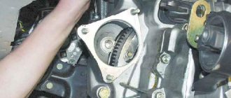
Replacing the timing belt on a VAZ-2113, 2114, 2115
As for the latter, its gear ratio is 3.53. Reverse speed ensures that the transmission shaft rotates in the opposite direction. To do this, it needs an additional shaft with a separate gear. As a result, the number of gear pairs changes to an odd number, and the torque changes its direction. Also, this transmission does not have a synchronizer - it will not be possible to turn it on at speed. The VAZ-2114 gearbox has a gear with an equal gear ratio, which is 0.941. This is fourth speed. Thus, the transmission output shaft rotates with the same force as the secondary one. That is, the angular speed of rotation of the two elements is the same. Motorists call it “straight”.
Instructions for removing, disassembling and assembling the VAZ 2114 gearbox
Removing the gearbox is required when troubleshooting parts and the mechanism of the gearbox itself; when replacing the clutch.
Repair work may require one business day, so the instructions below must be started in the morning. Hiring a partner with experience in this type of repair will reduce time costs and improve the quality of repairs.
Preparation
The preparation process consists of the following steps:
Removing and disassembling the gearbox. Procedure for cleaning gearbox parts
We perform the following steps sequentially:
Replacing a broken clutch on a car
You can replace the mechanism yourself, without resorting to the services of a car service. Without changing the oil and dismantling the right CV joint, this is quite easy to do.
All work must be carried out with the vehicle raised, so you should first disable and remove all components and parts that may interfere.
Required Tools
To replace, you will need the following tools:
- set of wrenches;
- balloon wrench.
- removable key for removing the ball joint;
- jack;
- rope;
- screwdriver;
- beam for hanging the engine;
- small crowbar or pry bar;
- mandrel for centering the disk.
Procedure
- The negative terminal is disconnected from the battery.
- The air purification system and its sensor are dismantled.
- The clutch cable is disconnected.
If necessary, replace the clutch cable with a new one
To facilitate access to the clutch, the engine protection is removed
Removing the clutch basket from a raised vehicle
During the replacement process, you should evaluate the performance of the removed components and parts of the car, and, if necessary, replace them with new ones.