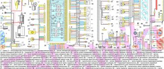
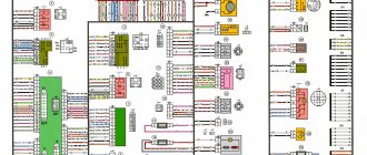
1 – ignition coils 2 – injectors 3 – controller 4 – main relay 5 – fuse connected to the main relay 6 – cooling system electric fan relay 7 – fuse connected to the cooling system electric fan relay 8 – electric fuel pump relay 9 – fuse connected to electric fuel pump relay 10 – mass flow and air temperature sensor 11 – throttle position sensor 12 – coolant temperature sensor 13 – canister purge solenoid valve 14 – oxygen sensor 15 – knock sensor 16 – crankshaft position sensor 17 – idle speed control 18 – immobilizer control unit 19 – immobilizer status indicator 20 – phase sensor 21 – vehicle speed sensor 22 – electric fuel pump module with fuel level sensor 23 – oil pressure warning lamp sensor 24 – coolant temperature indicator sensor
A – block connected to the wiring harness of the ABS cabin group B – diagnostic block C – block connected to the air conditioner wiring harness D – to the “+” terminal of the battery D – to the side door wiring harness block E – block connected to the panel wiring harness devices
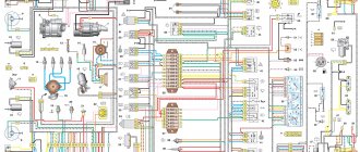
VAZ-2112 wiring diagram
Wiring diagram for a car in a hatchback body (click on the picture to enlarge)
Designations: 1 – Headlight, 2 – Horn, 3 – Main radiator fan, 4 – Starter, 5 – Battery, 6 – Generator, 7 – Gearbox limit switch (reverse), 8 – Actuator in the front passenger door, 9 – Relay power windows permissions, 10 – Starter relay, 11 – Heater fan, 12 – Electric heater partition drive, 13 – Main pump, 14 – Washer reservoir sensor, 15 – Driver’s door actuator, 16 – Front passenger window selector, 17 – Fifth wheel release button doors, 18 – Heater fan resistance unit, 19 – Main wiper motor, 20 – Driver's window lift selector, 21 – Front passenger's window lift motor, 22 – Central locking, 23 – Exterior light switch, 24 – Brake fluid leakage sensor, 25 – Additional pump , 26 – Driver's window lift motor, 27 – PTF on indicator, 28 – PTF switch, 29 – Dashboard , 30 – Heated glass on indicator, 31 – Heated glass switch, 32 – Steering column selector switch, 33 – PTF relay, 34 – Ignition switch , 35 – Main fuse block, 36 – Illumination of heater controls, 37 – Hazard warning button, 38 – Heater control controller, 39 – Glove compartment lighting, 40 – Glove compartment lid end cap, 41 – Cigarette lighter, 42 – BSK – display unit, 43 – Ashtray illumination, 44 – 12V socket, 45 – Instrument lighting switch, 46 – Actuator in the right rear door, 47 – Right rear passenger window selector, 48 – Clock, 49 – Right rear passenger window motor, 50 – Brake limit switch (closed – pedal is pressed), 51 – Left rear passenger window motor, 52 – Left rear passenger window selector, 53 – Actuator in the left rear door, 54 – Turn signal, 55 – Handbrake limit switch (closed – handbrake on), 56 – Rear wiper motor, 57 – Navigator’s lamp, 58 – Interior lamp, 59 – Temperature sensor in the heater, 60 – Limit switch for an open front door, 61 – Limit switch for an open rear door, 62 – Trunk lighting, 63 – Rear optics (on the body), 64 – Rear optics ( on the fifth door), 65 – License plate illumination.
The letters indicate the terminals to which it is connected: A – Front speaker on the right, B – Radio, C – Injector harness, D – ESD diagnostic connector, D – Front left speaker, E – Diagnostic connector for the heater controller, G – Rear right speaker, W – Rear left speaker, I – BC connector, K – glass heater thread, L – fifth door actuator, M – Additional brake light.
All door switches remain open when the doors are closed. We provide a wiring diagram for the VAZ-2112 with a description, and information about the limit switches will be useful to signal installers.
Please note that starter power may be connected in different ways. Either the current to terminal 50 comes directly from the lock, or through relay 10. The second option (as in the diagram) is less common.
The three relays shown in the diagram are always installed on a block mounted on top of block 35 (see photo).
Main fuse and relay box
Here part 5 is “relay 9”, and part 7 is “relay 10”.
Window lifters
When the ignition is turned on, relay 11 closes its contacts. This enables the operation of the power windows controlled by selectors 3, 4, 9 and 10.
Without the ignition, the power windows don't work.
The diagram does not require any other explanation.
central locking
The diagram shows four actuators, as well as control unit 3. Actuator 7 is located in the driver's door.
Actuators, central locking unit and one limit switch
It would seem that everything is simple here. But in the description of the VAZ-2112 electrical circuit, the main thing is usually not reported: the white cord is the input for the “Open” command, the brown one is the “Close” command.
There is a variant of the circuit where module 7 contains only a limit switch (without an actuator).
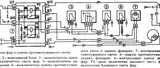
Relay K4 turns on the low beam lamps, K5 - high beam.
Headlights with single-filament lamps
Selector lever 3 only switches on relay K5. But in the explanation to the electrical diagram on the VAZ-2112 it is said that:
It's simple: when switch 4 is in position II, relay K4 closes its contacts. This means that in the “high beam” mode all the lamps work at once.
Dimensions, brake light, backlight
Side lights 1 and 6 are turned on by switch 3. From it, the current flows through the main unit 2, or rather, through the lamp serviceability relay. The diagram shows jumpers instead of relay K1.
Dimensions, license plate lights, brake lights, instrument lights
The license plate lighting is lamps 8. They turn on regardless of the operation of the relay. The operation of the reverse lamps also does not depend on relay K1, as well as on switch 3. It is regulated only by limit switch 10. The brake light lamps are switched on in a similar way (limit switch 11).
The brightness of the instrument lighting is controlled by resistor 9. But there is a caveat: switch 3 must be in position I or II. These positions correspond to the inclusion of indicator 5 (on the dashboard).
Turn signals
Turn signal lamps 1, 5 and 6 are activated by switch 7. The power supply circuit for these lamps includes a relay-breaker K3, which alternately closes contacts 49a-49 and 49a-31.
The basis of the circuit is a relay-interrupter
Without power supply from the ignition switch, the turn signals do not work. There is also an “Alarm” operating mode when:
If contact is broken in the socket of one of the lamps, the operating frequency of relay K3 doubles. In normal condition, it is 1.2-1.9 Hz.
Car fuses - number, current and description
F1 5 Lighting lamps: numbers, instruments, dimensions on the dashboard, left dimensions, trunk lighting F2 7.5 Low beam in the left headlight F3 10 High beam in the left headlight F4 10 Right front fog lamp F5 30 Door windows F6 15 Portable lamp, cigarette lighter F7 20 Radiator fan, horn F8 20 Heated rear window F9 20 Windshield washer and cleaner F10 20 Reserve F11 5 Clearance on the right side F12 7.5 Low beam in the right headlight F13 10 High beam in the right headlight F14 10 Fog lamp, left F15 20 Heated seats 21124 F16 10 Hazard signal, turn signals F17 7.5 Brake light, ignition switch illumination, interior lighting F18 25 Cigarette lighter, glove compartment light, interior heater F19 10 Reversing lamp, brake light monitoring F20 7.5 Rear fog lights headlights
CAR ELECTRONICS REPAIR
VAZ-2112 diagram
The VAZ-2112 car was produced at AvtoVAZ from 1998 to 2009, in Ukraine from 2009 to 2014. The following are color wiring diagrams (injector and carburetor) with a description of all elements for various modifications. The information is intended for self-repair of cars. Electrical circuits are divided into several blocks for ease of viewing via a computer or smartphone; there are also circuits in the form of a single picture with a description of the elements - for printing on a printer in one sheet.
To diagnose and repair yourself, first look to see if everything is okay with the generator. Is it put on well and does not sag? This procedure must be done with all versions of the fuel system, both carburetor and injection. We check the fuses according to the electrical diagram. The reverse side of the safety block cover will also be of great help. There are clues there that the diagram will help you decipher. Replace the burnt out element and try to start the car again. You need to check whether the battery terminals are tightly connected and whether they are oxidized. Is the wire going from the battery to the generator and to the starter damaged?
Unbreakable connection
The machine and its electrical circuit cannot exist separately; this union is indestructible, like the foundations of the Chinese wall.
Almost all systems, in one way or another, depend on electricity and, in its absence, not only refuse to work correctly, but do not function at all.
Here are just a few of these interactions:
- ignition of the combustible mixture in the fuel system of both carburetor and injection type engines;
- supplying electricity to the starter when starting the engine;
- instrument panel illumination at night;
- informing other road users about the desire to carry out a maneuver using a light indicator “right” or “left”;
- playing a sound signal to prevent an accident;
- turning on the side lights to identify the vehicle at night.
Let's move on to the electrical circuit itself.
Among other things, the presence in the “Manual” of printed electrical diagrams with detailed descriptions makes it an indispensable assistant in not only accurately identifying symptoms, but also “prescribing treatment”, finding out the most important question of why it hurts, and not just where.
It is important to understand from our diagram what the following auxiliary equipment is connected to:
- sound signal;
- wipers;
- cassette player or radio;
- interior lighting;
- heated rear and front windows;
- power windows (if equipped).
The task is important for the reason that in a car there is a certain interdependence of some (main) systems from others (auxiliary). Some work in pairs, while others work in threes or even fours. If you know exactly this connection, you will immediately find your bearings. If there is no current supply to the glow plugs, then, most likely, other subsystems that work together are not functioning.
Modifications of the VAZ-2112 car
VAZ-21120 . Modification with a 16-valve injection engine with a volume of 1.5 liters and a power of 93 horsepower. 14-inch wheels were installed on the car. This modification has a problem with valves bending when the timing belt breaks. The problem can be solved by increasing the depth of the grooves in the piston bottoms.
VAZ-21121 . The car was equipped with a VAZ-21114 8-valve injection engine with a volume of 1.6 liters and a power of 81 horsepower.
VAZ-21122 . Budget modification with an 8-valve injection engine VAZ-2111. The car was produced without electric windows, the wheels were 13 inches in size, and the brakes were unventilated from a VAZ-2108 car.
VAZ-21123 Coupe . Three-door, five-seater hatchback. The only two doors for entering the car are 200 millimeters wider than those of the five-door hatchback, and they are mounted on new, durable hinges. The rear arches of the car have become wider. The engine was installed with a 16-valve injection engine with a volume of 1.6 liters and a power of 90 horsepower. The car was produced from 2002 to 2006 in small quantities, the reason for this was the high cost of the car.
VAZ-21124 . Modification with a 16-valve injection engine VAZ-21124 with a volume of 1.6 liters. Produced from 2004 to 2008. For this type of engine, the problem with valve bending was solved. To do this, the depth of the grooves in the piston heads was increased (up to 6.5 mm). In addition, the design of the cylinder block was changed to achieve a working volume of 1.6 liters, for which its height was increased by 2.3 mm, and the radius of the crankshaft was increased by 2.3 mm accordingly. There were also a number of other minor changes.
VAZ-21128 . The luxury version of the car, produced by Super-auto JSC, was equipped with a 16-valve VAZ-21128 engine with a volume of 1.8 liters and a power of 105 horsepower.
VAZ-2112-37 . A racing modification of the VAZ-2112, prepared for the “ring” in the Lada Cup qualifying group. The car was equipped with a 1.5-liter VAZ-2112 engine with a power of 100 horsepower. The racing car was equipped with a safety cage, an external aerodynamic kit and a front extension of the strut support cups.
VAZ-2112-90 Tarzan . All-wheel drive modification with a VAZ-2112 body on a frame chassis with transmission and suspension parts from a VAZ-21213 Niva. It was also equipped with a 1.7 or 1.8 liter engine from the Niva.
The car does not start - there is no charge in the battery
This problem occurs because the battery charge is going somewhere. It does not disappear by chance, but always for some reason.
Here are some of them:
- you leave the car outside at an ambient temperature of -20 degrees or below;
- the battery life is ending;
- The radio was left on in your car for some time, which led to a loss of charging power.
In all these cases, two types of treatment are usually used: firstly, urgently recharge, and secondly, buy a new battery. If you keep pulling and driving on a dead battery, soon you won't even be able to disarm your car. You will have to manually remove the terminals, trying to make it “silence”. The situation will immediately improve as soon as the battery is charged again.
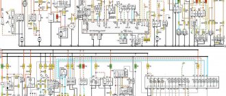
Electrical diagram of VAZ-2112
Designations: 1 – Headlight, 2 – Klaxon, 3 – Main radiator fan, 4 – Starter, 5 – Battery, 6 – Generator 2112, 7 – Gearbox limit switch (reverse), 8 – Actuator in the front passenger door, 9 – Power window enable relay, 10 – Starter relay, 11 – Heater fan, 12 – Electric heater partition drive, 13 – Main pump, 14 – Washer reservoir sensor, 15 – Driver’s door actuator, 16 – Front passenger window selector, 17 – Unlock button fifth door, 18 – Heater fan resistance unit, 19 – Main wiper motor, 20 – Driver’s window lift selector, 21 – Front passenger’s window lift motor, 22 – Central locking, 23 – Exterior light switch, 24 – Brake fluid leakage sensor, 25 – Pump additional, 26 – Driver's window lift motor, 27 – PTF on indicator, 28 – PTF switch, 29 – Dashboard, 30 – Heated glass on indicator, 31 – Heated glass switch, 32 – Steering column selector switch, 33 – PTF relay, 34 – Ignition switch, 35 – Main fuse block, 36 – Illumination of heater controls, 37 – Hazard warning button, 38 – Heater control controller, 39 – Glove compartment lighting, 40 – Glove compartment lid end cap, 41 – Cigarette lighter, 42 – BSK – display unit, 43 – Ashtray illumination, 44 – 12V socket, 45 – Instrument lighting switch, 46 – Actuator in the right rear door, 47 – Right rear passenger window selector, 48 – Clock, 49 – Right rear passenger window motor, 50 – Brake limit switch (closed – pedal is pressed), 51 – Left rear passenger window motor, 52 – Left rear passenger window selector, 53 – Actuator in the left rear door, 54 – Turn signal, 55 – Handbrake limit switch (closed – handbrake on), 56 – Rear wiper motor , 57 – Navigator's lamp, 58 – Interior lamp, 59 – Temperature sensor in the heater, 60 – Limit switch for the open front door, 61 – Limit switch for the open rear door, 62 – Trunk light, 63 – Rear optics (on the body), 64 – Rear optics (on the fifth door), 65 – License plate illumination.
The letters indicate the terminals to which it is connected: A – Front speaker on the right, B – Radio, C – Injector harness, D – ESD diagnostic connector, D – Front left speaker, E – Diagnostic connector for the heater controller, G – Rear right speaker, W – Rear left speaker, I – BC connector, K – glass heater thread, L – fifth door actuator, M – Additional brake light.
Wiring diagram VAZ-2112 injector 16 valves - full view
Where to look for the connector
It is important to know that on different cars the required socket is located in different parts of the car. Moreover, on some AvtoVAZ models it may be in a completely different place compared to another car. Let's look at several VAZ cars as an example:
- on the VAZ-2112, as well as on the 2110, as well as 2111, the socket is located to the right of the driver’s seat, immediately under the column;
- on models 2108, 2109 and 21099, the socket you need is located under the glove compartment, on a special shelf;
- on cars with a europanel it can be found in the center of the console, near the cigarette lighter. A special decorative cover is used to disguise it;
- on Lada Kalina cars, the connector can be found near the gear shift lever. As is the case with cars with a Europanel, it is hidden under a special cover;
- on a Priora you need to look for it right behind the glove compartment, on the wall.
VAZ-21124 engine control circuit
Connection diagram of the VAZ-21124 engine control system with distributed fuel injection to Euro-2 emission standards (controller M7.9.7): 1 - ignition coils; 2 — nozzles; 3 - controller; 4 - main relay; 5 - fuse connected to the main relay; 6 — cooling system electric fan relay; 7 - fuse connected to the cooling system electric fan relay; 8 - electric fuel pump relay; 9 - fuse connected to the electric fuel pump relay; 10 — mass flow and air temperature sensor; 11 — throttle position sensor; 12 — coolant temperature sensor; 13 — solenoid valve for purge of the adsorber; 14 — oxygen sensor; 15 — knock sensor; 16 — crankshaft position sensor; 17 — idle speed regulator; 18 — immobilizer control unit; 19 — immobilizer status indicator; 20 - phase sensor; 21 — vehicle speed sensor; 22 — electric fuel pump module with fuel level sensor; 23 — oil pressure warning lamp sensor; 24 — coolant temperature indicator sensor; A - block connected to the wiring harness of the ABS cabin group; B — diagnostic block; B - block connected to the air conditioner wiring harness; G - to the “+” terminal of the battery; D — to the side door wiring harness block; E - block connected to the instrument panel wiring harness; G1, G2 - grounding points; I - the order of conditional numbering of plugs in the block of the immobilizer control unit; II - the order of conditional numbering of contacts in the diagnostic block.
Connection diagram of the VAZ-21124 engine control system with distributed fuel injection under Euro-3 toxicity standards (controller M7.9.7): 1 - ignition coils; 2 — nozzles; 3 - controller; 4 - main relay; 5 - fuse connected to the main relay; 6 — cooling system electric fan relay; 7 - fuse connected to the cooling system electric fan relay; 8 - electric fuel pump relay; 9 - fuse connected to the electric fuel pump relay; 10 — mass flow and air temperature sensor; 11 — rough road sensor; 12 — throttle position sensor; 13 — coolant temperature sensor; 14 — idle speed regulator; 15 — control oxygen sensor; 16 — diagnostic oxygen sensor; 17 — solenoid valve for purge of the adsorber; 18 — knock sensor; 19 — crankshaft position sensor; 20 — immobilizer control unit; 21 — immobilizer status indicator; 22 - phase sensor; 23 — vehicle speed sensor; 24 — electric fuel pump module with fuel level sensor; 25 — oil pressure warning lamp sensor; 26 — coolant temperature indicator sensor; A - block connected to the wiring harness of the ABS cabin group; B — diagnostic block; B - block connected to the air conditioner wiring harness; G - to the “+” terminal of the battery; D — to the side door wiring harness block; E - block connected to the instrument panel wiring harness; G1, G2 - grounding points; I - the order of conditional numbering of plugs in the block of the immobilizer control unit; II - the order of conditional numbering of contacts in the diagnostic block.
How does the controller monitor the operation of the injector?
When determining the specific position and opening time of the injector design, the specific volume of fuel entering the valves of the VAZ-2110 cylinder is determined. At the same time, thanks to special sensors installed on the motor, the on-board computer records specific values and transmits them to the controller.
Subsequently, the controller, based on the information coming from the on-board computer, makes a decision on the position and duration of opening of the injector damper. If the controller malfunctions, the injectors will not be adjusted correctly, and the engine may stall while driving.
Tip: when starting the engine, the injector controller operates in asynchronous mode until the engine reaches a certain number of revolutions. That is why, after replacing the silent blocks of the front control arms on a VAZ-2110, you should warm up the car for 10-15 minutes.
VAZ-2112 diagram
The VAZ-2112 car was produced at AvtoVAZ from 1998 to 2009, in Ukraine from 2009 to 2014. The following are color wiring diagrams (injector and carburetor) with a description of all elements for various modifications. The information is intended for self-repair of cars. Electrical circuits are divided into several blocks for ease of viewing via a computer or smartphone; there are also circuits in the form of a single picture with a description of the elements - for printing on a printer in one sheet.
To diagnose and repair yourself, first look to see if everything is okay with the generator. Is it put on well and does not sag? This procedure must be done with all versions of the fuel system, both carburetor and injection. We check the fuses according to the electrical diagram. The reverse side of the safety block cover will also be of great help. There are clues there that the diagram will help you decipher. Replace the burnt out element and try to start the car again. You need to check whether the battery terminals are tightly connected and whether they are oxidized. Is the wire going from the battery to the generator and to the starter damaged?
Modifications of the VAZ-2112 car
VAZ-21120. Modification with a 16-valve injection engine with a volume of 1.5 liters and a power of 93 horsepower. 14-inch wheels were installed on the car. This modification has a problem with valves bending when the timing belt breaks. The problem can be solved by increasing the depth of the grooves in the piston bottoms.
VAZ-21121. The car was equipped with a VAZ-21114 8-valve injection engine with a volume of 1.6 liters and a power of 81 horsepower.
VAZ-21122. Budget modification with an 8-valve injection engine VAZ-2111. The car was produced without electric windows, the wheels were 13 inches in size, and the brakes were unventilated from a VAZ-2108 car.
VAZ-21123 Coupe. Three-door, five-seater hatchback. The only two doors for entering the car are 200 millimeters wider than those of the five-door hatchback, and they are mounted on new, durable hinges. The rear arches of the car have become wider. The engine was installed with a 16-valve injection engine with a volume of 1.6 liters and a power of 90 horsepower. The car was produced from 2002 to 2006 in small quantities, the reason for this was the high cost of the car.
VAZ-21124. Modification with a 16-valve injection engine VAZ-21124 with a volume of 1.6 liters. Produced from 2004 to 2008. For this type of engine, the problem with valve bending was solved. To do this, the depth of the grooves in the piston heads was increased (up to 6.5 mm). In addition, the design of the cylinder block was changed to achieve a working volume of 1.6 liters, for which its height was increased by 2.3 mm, and the radius of the crankshaft was increased by 2.3 mm accordingly. There were also a number of other minor changes.
VAZ-21128. The luxury version of the car, produced by Super-auto JSC, was equipped with a 16-valve VAZ-21128 engine with a volume of 1.8 liters and a power of 105 horsepower.
VAZ-2112-37. A racing modification of the VAZ-2112, prepared for the “ring” in the Lada Cup qualifying group. The car was equipped with a 1.5-liter VAZ-2112 engine with a power of 100 horsepower. The racing car was equipped with a safety cage, an external aerodynamic kit and a front extension of the strut support cups.
Common faults
As you can see, in general, a 16-valve engine is a rather complex system. Accordingly, there are also enough breakdowns in its operation; all of them can be divided into several groups. For example, if you have suspicions about the functionality of the spark plugs, and they turned out to be working, then you need to check the operation of the ignition coil and high-voltage cables. As practice shows, breakdowns in the wires can also lead to incorrect operation of the ignition system. Failure of one or another element of the electrical network can be a consequence of either a breakdown of the device itself or a failure of the generator unit or battery.
Most often, car owners are faced with the problem of battery failure, so let’s look at the main malfunctions characteristic of this device:
- a short circuit has occurred between the electrodes of the device;
- damage to the plates located inside;
- the appearance of cracks and other mechanical damage on the battery case, as well as shedding of the plates, which can lead to leakage of electrolyte;
- oxidation of the battery terminals, this problem can be solved by stripping.
All these faults ultimately lead to battery discharge. If we talk about the reasons that caused these problems, then most likely they all lie in incorrect operation, of course, if the battery life is high and has not yet expired. Much less often, the malfunction lies in a manufacturing defect, but this happens infrequently.
To prevent malfunctions in the operation of the battery, the following rules should be taken into account during operation:
- Firstly, the device must be securely fixed at the landing site. If the battery is not secured securely, this can lead to constant vibration, which can subsequently cause cracks in the case.
- Operation of the car and, accordingly, the use of the electrical network is allowed only when using a working generator. If the alternator is faulty or its belt tension is weak, it will ultimately lead to battery discharge.
- If the contact at the device terminal is poor, this can lead to its oxidation and destruction.
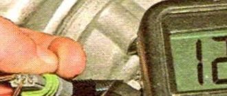
- Cranking the starter for a long time when trying to start the engine also contributes to battery discharge. This problem especially often manifests itself in cold weather, when the battery electrolytes are less mobile, and the driver has to turn the starter longer to start it (the author of the video is Vyacheslav Kravchenko).
Repairing a VAZ 2111. The would-be electricians almost burned the car.
Depending on the type and manufacturer, the battery life can range from three to five years. However, the service life may be shorter if the battery is used intensively and in harsh conditions. One way or another, the consequence of battery discharge is always the same - the device will not be able to crank the starter to start the engine, as well as power the devices and equipment of the car as a whole. If the diagnostics show that the battery is working normally, the cause of the malfunction may lie in the performance of the generator.
Its design as a whole is more complex; accordingly, this unit has a lot of faults:
- erasing of brushes due to their wear;
- voltage regulator relay failure;
- failure of the diode bridge;
- bearing wear, which is accompanied by a hum when the generator operates;
- wear of slip rings;
- damage or wear of pulley teeth;
- short circuit in the stator winding;
- damage to the charging circuit wiring;
- broken or worn alternator belt.
Malfunctions in the operation of the unit can be determined by diagnostics using a multimeter. As for repairs, you can do it yourself. We have previously described the procedure for repairing a generator using the VAZ 2114 model as an example in this article; in the case of the VAZ 2111 it looks similar.
As for other malfunctions in the operation of the electrical circuit, there may be several reasons:
- failure of the device itself;
- fuse blown caused by a short circuit (before replacing the fuse, it is necessary to determine the cause of the short circuit);
- electrical circuit breakage, the problem is solved by replacing the wire;
- oxidation of contacts on device terminals (video author - Ramanych channel).
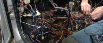
We treat wiring VAZ 2110 16V
Stories from our readers
“Fucking basin. "
Hi all! My name is Mikhail, now I’ll tell you a story about how I managed to exchange my two-wheeler for a 2010 Camry. It all started with the fact that I began to be wildly irritated by the breakdowns of the two-wheeler, it seemed like nothing serious was broken, but damn it, there were so many little things that really started to irritate me. This is where the idea arose that it was time to change the car to a foreign car. The choice fell on the melting Camry of the tenth years.
Yes, I had matured morally, but financially I just couldn’t handle it. I’ll say right away that I am against loans and taking a car, especially not a new one, on credit is unreasonable. My salary is 24k a month, so collecting 600-700 thousand is almost impossible for me. I started looking for different ways to make money on the Internet. You can’t imagine how many scams there are, what I haven’t tried: sports betting, network marketing, and even the volcano casino, where I successfully lost about 10 thousand ((The only direction in which it seemed to me that I could make money was currency trading on the stock exchange, they call it Forex. But when I started delving into it, I realized that it was very difficult for me. I continued to dig further and came across binary options. The essence is the same as in Forex, but it’s much easier to understand. I started reading forums, studying trading strategies. I tried it on a demo account, then opened a real account. To be honest, I didn’t manage to start earning money right away, until I understood all the mechanics of options, I lost about 3,000 rubles, but as it turned out, it was a precious experience. Now I earn 5-7 thousand rubles a day. I managed to get the car buy after half a year, but in my opinion this is a good result, and it’s not about the car, my life has changed, I naturally quit my job, I have more free time for myself and my family. You’ll laugh, but I work directly on the phone)) If If you want to change your life like me, then here’s what I advise you to do right now: 1. Register on the site 2. Practice on a Demo account (it’s free). 3. As soon as you get something on the Demo account, top up your REAL ACCOUNT and go to REAL MONEY! I also advise you to download the application to your phone, it’s much more convenient to work from your phone. Download here.
- K1 – lamp health monitoring relay (contact jumpers are shown inside, which are installed instead of the relay);
- K2 – windshield wiper relay;
- K3 – relay-interrupter for direction indicators and hazard warning lights;
- K4 – headlight low beam relay;
- K5 – headlight high beam relay;
- K6 – additional relay;
- K7 – relay for turning on the heated rear window;
- K8 – backup relay (not installed on vehicles of the VAZ-2110 family);
Installation of fog lights
Car owners can independently equip their car with fog lights. For ease of installation, you can watch videos from forums where masters share their experience of such work.
VAZ 2112 Wiring of fog lights (Luxury degree)
Conclusions: in fact, replacing old wiring in the rear of the car is much easier than in the engine compartment or inside the cabin. And the diagrams proposed in the article will help you figure it out faster and prevent mistakes.
Pinout
Knowledge of pinouts may be required if a car enthusiast wants to make an adapter for computer diagnostics with his own hands, or if you need to connect without one. Experts recommend buying ready-made devices without the need to make a plug yourself. However, if you do not have such an opportunity, and diagnostics need to be carried out urgently, we will consider two main pinout options used on VAZ cars of various years of manufacture. Until 2002, AvtoVAZ products used the following pinout option:
- The 4th and 5th pins are GND outputs.
- Pin 16 – +12 V (power line).
- The 7th contact is the diagnostic line itself.
Since 2002, the pinout scheme has changed significantly. Now it looks like this:
- Pin H – +12 V (power line).
- Contact G – +12 V for the fuel pump.
- Pin A – GND output.
- Contact M – diagnostic line.
Electromagnetic relays
To relieve the car switch contacts from high current consumption, electromagnetic relays are used in the electrical circuit. There are 8 of them in total:
- K1 is responsible for the serviceability of the lamps;
- for turning on the front window wiper - K2;
- for turn signals and hazard warning lights – K3;
- for low beam headlights - K4;
- for turning on the high beam - K5;
- for heating the rear window - K7;
- for fog lights located at the rear - K8.
The block contains relay K6, which is additional. Before installing a new element into the system, check the wiring for short circuits, otherwise the parting that is protected by the fuse element or the fuse itself may fail. The described block is the main one, but the only one in the VAZ-2112 electrical circuit.
Instructions for performing diagnostics
To diagnose a VAZ, a computer or diagnostic equipment is connected using a diagnostic connector.
Computer diagnostic socket
All broadcast codes are read by the scanner. They are stored in the controller’s memory until its power is turned off. Using special software, specialists decipher the codes and determine what malfunctions and failures exist in the system.
The diagnostic procedure consists of several stages:
- Suspension diagnostics. This procedure is performed if uneven tire wear, knocking or humming is detected when driving at a constant speed, making sharp turns, or on an uneven road. And also in case of premature activation of the ABC, increased free play of the steering wheel.
- Engine check. The power engine should be diagnosed if it runs intermittently, takes a long time to heat up, is difficult to start, as well as with increased fuel consumption, loss of power, the appearance of extraneous noise, or a decrease or increase in idle speed. During diagnostics, the electrical supply and ignition system are checked, and the pressure in the cylinders is measured (the author of the video is Pavel Master).
An automatic transmission is diagnosed in the following cases:
- no gear is engaged;
- When changing gears, noises, jerking, and slipping appear;
- increased fuel consumption;
- Oil leak detected.
During diagnostics, the scanner reads error codes of the automatic transmission control system, evaluates the readings of the throttle position and cooling system temperature sensors, as well as the position of the automatic transmission selector.
First of all, diagnostics are performed using a scanner. The scanner readings are deciphered and conclusions are drawn about problems in the system. At the second stage, analog testing is carried out - wiring, contacts, and batteries are checked. Next, an online check is carried out. The screen displays indicators of sensors, fuel injection, etc. Then the data obtained during posting is analyzed. At the last stage, the error codes stored in the controller’s memory are erased. After this, reinitialization is necessary.