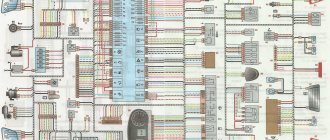
The modern Lada Granta model is in demand among domestic car enthusiasts due to its optimal cost and sufficient reliability. Good strength and low cost of consumables further stimulate demand among the population. The downside of the car is frequent breakdowns in the electrical part. On-board systems often fail. The website contains a detailed electrical diagram of Grant with explanations and interpretation.
Full pinout of Grant, divided into several sections for a more detailed image and easier perception. Present here.
- The engine compartment - the harness combines all the elements of the wires located in the area of the engine and main instruments.
- Salon module. The design is further divided into zones that provide for the connection of individual parts of the wiring.
- Instrument panel module. All elements coming from sensors, instruments and indicators are concentrated here.
- The rear harness is located in the rear of the car and is responsible for supplying power to the lighting, lock and instrument modules.
All the given transcripts are taken from the manufacturer’s official instructions and fully comply with the factory designations and the standard version diagram.
Grant's electrical circuit responsible for the engine compartment
Here are the main parts of the Lada Granta wiring, which are responsible for the normal operation of the power plant:
- 1 – power supply to the headlight, front right;
- 2 – power supply for windshield washers;
- 3 – voltage to the left side of the head optics;
- 5 – on-board power supply;
- 6 – head fuse block;
- 7 – generator;
- 8 – horn;
- 9-11 – terminal blocks to the dashboard;
- 12 – contact pair of rear headlights;
- 13 – main radiator fan drive.
Lada Granta diagram - ignition part
- 1 – indicator of lubricant pressure in the crankcase of the power plant;
- 2 – generator connector;
- 3 – power supply to the fuel mixture supply valve;
- 4 – cooling system thermometer;
- 5 – sending a signal to the dashboard;
- 6 – adsorber purge;
- 7 – speedometer;
- 8 – mass air flow sensor;
- 9 – DPKV;
- 10 – DC in front of the catalyst;
- 11 – control pulse device;
- 12 – oxygen concentration sensor in exhaust gases;
- 13/14 – coil and spark plugs, respectively;
- 15 – injector drivers;
- 16 – ignition contact group;
- 17 – detonation measurement sensor.
Assignment of contacts of Bosch M ECU 1. 5 . 4, MP 7. 0 and January‑5. 1
Note: In the second column, missing elements in the ECM January 5 are highlighted in blue. 1 . 2, which does not use an adsorber and an oxygen sensor. In the third column, elements of the Euro-3 system that are absent in Euro-2 are highlighted in red
We draw your attention to the fact that this website is for informational purposes only and under no circumstances is it a public offer defined by the provisions described in Part 2 on page 437 of the Civil Code of the Russian Federation.
Grant instrument pinout - dashboard diagram
This part is the most difficult. The large number of pins and the miniature size of the terminals greatly complicates the search for the required group:
- 1/2 – connecting blocks for the front electrical harness;
- 3/4 – similar for the feed harness;
- 5 – lighting control unit;
- 6 – ignition switch module;
- 7 – on-board computer;
- 8 – lever for switching the position of the wipers;
- 9 – tidy;
- 10 – control of emergency modes;
- 11 – cargo compartment lid lock;
- 12 – diagnostic connector;
- 13 – block for the air intake drive;
- 14 – button to turn off the heated rear windshield;
- 15 – emergency contact;
- 16 – brake light switch;
- 17/18 – contact group – output to radio equipment (radio tape recorder);
- 19 – rotating equipment module;
- 20/41 – driver/passenger airbag drive;
- 21 – horn power supply;
- 22 – mounting block group;
- 24 – cigarette lighter group;
- 25 – backlight for stove control;
- 26 – interior lamp;
- 27 – contact group of the ignition switch;
- 28 – controller;
- 29 – incoming connector to the rear of the on-board network;
- 30 – electronic part of the gas pedal;
- 31 – additional resistor;
- 32 – stove motor;
- 33 – heater switch block;
- 34 – door lock module;
- 35/36 – cooling system head fan relay;
- 37 – compressor relay wiring;
- 38 – additional relay or reverse indication coil;
- 39 – air conditioner switch button;
- 40 – automatic transmission drive;
- 42 – evaporator thermometer;
- 43 – output to the rear wiring harness.
Diagrams of other connectors of electronic control units
Renix ECU
ECU 2LT-E, KZN165, KZJ90
Passat ECU
Progress electronic control unit
Mitsubishi ECU
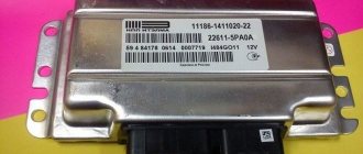
Grant ECU pinout
The Lada Granta uses two types of electronic engine control units. Fundamentally, the systems differ slightly, which excludes the possibility of their interchangeability.
| Contact | 11183-1411020-51/52 | 11186-1411020-21/22 |
| A1 | DPKV | |
| A2 | Not involved | |
| A3 | Entering the first knock sensor | |
| A4 | Not used | |
| IN 1 | DPKV | |
| AT 2 | Not involved | |
| AT 3 | Input of the second knock sensor | |
| AT 4 | Main relay output | Not used |
| C1 | Empty | |
| C2 | DTV | |
| C3 | Mass air flow sensor | |
| C4 | UDC | |
| D1 | DDC weight | |
| D2 | Empty | |
| D3 | DTOZH | |
| D4 | Not applicable | |
| E1 | Zeroing the TPS | |
| E2 | Empty | CAN L |
| E3 | Empty | CAN H |
| E4 | Canister purge valve output | |
| F1 | Body from DTV | |
| F2 | Speedometer input | |
| F3 | Not applicable | DFM |
| F4/G4/H4/J4 | Output from injector No. 1/2/3/4 | |
| G1 | Antifreeze temperature sensor ground | |
| G2/G3 | Not used | |
| H1 | On-board electronics grounding | |
| H2 | UDC | |
| H3 | Not involved | Battery charge indicator output |
| J1 | Terminal No. 15 from the ignition switch | empty |
| J2 | Entrance No. 2 TPS | |
| J3 | DDC | |
| K1 | Supplying voltage to the TPS | |
| K2 | Entrance No. 1 TPS | |
| K3 | UDC | |
| K4 | DDK heater power connector | |
| L1/M1 | Leads to the ignition coil ¼ and 2/3 cylinders respectively | |
| L2/M2; L3/M3 | Not involved | |
| L4/M4 | Throttle actuator pin 5/6 | |
What types of ECUs are available to Granta and what is the principle of their operation?
Sometimes the Lada Granta model is identified with an exclusive car. Why is she given such status? It's simple. "Lada" has a unique control unit, which is called "Itelma 11186-1411020-22" and cannot be combined with previous modifications of "VAZ". The primary difference of this module is the integrated “CAN bus”. Previously produced models used the “K-channel” to ensure the transmission of pulses. If you set out to experiment and replace the Itelma with a similar device with functionality in the K-channel, then in the end the devices on the panel will certainly “fall asleep”.
Where is the ECU located and what is its operating principle? It is based on a special type of algorithm, the formation of which occurs on the basis of software pre-integrated into memory. This allows the module to process signals from all sensors present in the ECM in real time.
Grant relay diagram
Relay location in the main mounting block located in the engine compartment:
- 1 – drive of the cooler of the cooling system;
- 2 – central locking protection;
- 3 – secondary starter relay;
- 4 – additional part of the relay;
- 5 – turn signal and emergency signal breaker relay;
- 6 – wiper drive protection;
- 7/9 – insertion of high/low headlight modes;
- 8 – horn protection element;
- 10 – heated aft windshield;
- 11 – main relay block;
- 12 – fuel pump relay.
Detailed diagram of the VAZ Grant (dashboard)
The vehicle is supplied to the market with a 32-pin instrument panel as standard. The standard pinout of the Grant shield has only 26 pins involved. Residual connectors are provided for the possibility of adding equipment or custom modifications:
- 1 – to the low oil pressure sensor in the engine crankcase;
- 2 – to the handbrake indication switch;
- 3 – intended for service needs when diagnosing the instrument panel;
- 4 – to external lighting switches;
- 5/6 – similar for right and left turn signals, respectively;
- 7/8 – CAN L/H;
- 9 – indication of seat belt position;
- 10 – contact of the Reset button of the steering column lever;
- 11 – response of the brake fluid reservoir sensor;
- 12/13 – on the head optics, high/low beam position;
- 14/15 – foglight terminals front/rear, respectively;
- 16/18 – receiving immobilizer antenna signal;
- 17 – ground wire of the instrument panel;
- 19/21 – to terminal No. 30/15;
- 20 – for the drive of the electric power steering unit;
- 22 – for door closing sensors;
- 23/24 – MK buttons for forward and reverse, respectively;
- 25 – for an environmental thermometer;
- 26 – gas tank float indication.
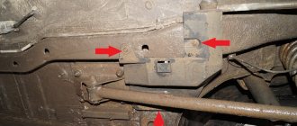
How to remove the ECU on a Lada Kalina - step-by-step instructions
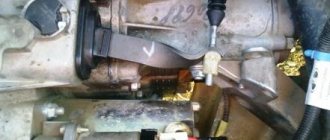
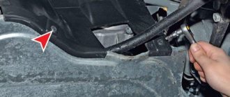
In order to remove the ECU unit on a Lada Kalina, you must perform the following procedure:
- First you need to unscrew 2 screws, the location of the first is shown by the arrow. The second is at the same level on the engine side. Before doing this, you must remember to remove the terminal from the battery. After unscrewing the screws, do you need to pull the block towards the passenger door? and he must leave from there along the guides. Sometimes it happens that the wires rest against the carpet. Then they need to be corrected.
- In order to remove the connector and disconnect the unit from the wires, you first need to: pull the connector lock to the side. The latch is a bracket. I think you can easily find it on the connector.
Lada Granta: wiring diagram for rear wiring harness devices
The rear part of the car wiring is responsible for the equipment of the stern and sides of the car. all additional equipment is connected exclusively through this part of the highways:
- 1/2 – contact group for the dashboard;
- 3/4 – direction indicators;
- 5 – handbrake indicator;
- 6 – rear window heating contact;
- 7 – interior lamp;
- 8 – indicator of the driver’s seat belt position;
- 9 – cargo compartment illumination lamp;
- 10 – fuel pump drive;
- 11/15 – aft dimensions for the left and right sides;
- 12 – trunk lid lock drive;
- 13 – button for turning on the interior lamp;
- 14 – additional stop chain;
- 16-19 – door terminal blocks for the rear left, rear right, front left and front right doors;
- 20 – airbag control drive;
- 21 – contact group of license plate lights;
- 22 – on the dashboard;
- 23/24 – rear speed indicator sensors;
- 25/26 – seat belt pretensioners;
- 27 – group of dashboard contacts.
Electrical diagram of VAZ 1118 (Norma package)
- Right block headlight;
- Hood open sensor;
- Sound signal;
- Starter;
- Accumulator battery;
- Generator;
- Windshield wiper gear motor;
- Left block headlight;
- Right front door power window switch;
- Right front door window regulator motor;
- Connection pads to the right front loudspeaker;
- Electric drive for locking the right front door lock;
- Windshield washer motor;
- Ambient temperature sensor;
- Engine control system wiring harness connection block;
- Electric drive for locking the left front door lock;
- Brake fluid level sensor;
- Connection pads to the left front speaker;
- Right front door power window switch located on the driver's door;
- Left front door power window switch;
- Door lock switch;
- Right front door window regulator motor;
- Mounting block;
- Automotive anti-theft system control unit;
- Security alarm control unit;
- Instrument cluster;
- Left side turn signal;
- Glove compartment lamp;
- Glove compartment lamp switch;
- Brake light switch;
- Ignition switch with car anti-theft system transponder;
- Control unit for external lighting, instrument lighting and headlight beam direction control;
- Understeering's shifter;
- Left side turn signal;
- Connection pads to the right rear speaker;
- Electric locking of the right rear door;
- Rear window heating switch;
- Reverse lock switch;
- Hazard switch;
- Heater fan operating mode switch;
- Additional resistor for heater fan motor;
- Heater fan motor;
- Connection pads to the left rear speaker;
- Electric drive for locking the left rear door;
- Electric fuel pump with fuel level indicator sensor;
- Reversing light switch;
- Parking brake warning switch;
- Cigarette lighter;
- Reverse lock solenoid;
- Connection blocks to the head unit of the sound reproduction system;
- Illumination lamps for the ventilation and heating system control unit;
- Electric power steering control unit;
- Interior lighting;
- Right rear light;
- Electric trunk lock;
- Trunk light switch built into the trunk lid lock;
- License plate lights;
- Additional brake signal;
- Rear window heating element;
- Trunk light;
- Left rear light.
This diagram does not show the connection points and wiring harness terminals.
Preventive measures
In order for the factory wiring of the Lada Grant to serve for a long time and not break, experienced experts strongly recommend following a number of simple rules.
- Periodically check all contact connectors and terminals for oxidation and rust. Such damage to the connections can cause a short circuit and a critical decrease in the conductivity of the line, which is perceived by the on-board computer as an error or breakdown.
- Use only original consumables and electronic components. The use of counterfeit products does not guarantee the functionality of the circuit. At the same time, some elements, when damaged, cause a voltage drop in the network, which becomes a direct cause of failure of other equipment or a fire.
- Use special oil to treat contact groups. The fluid is sold in auto shops or electronics stores. After treatment, the contacts are covered with a moisture-impermeable layer, which increases their service life by 2-3 times.
- Carefully monitor the charge level and condition of the battery. The wiring of the Lada Granta critically perceives a significant voltage drop in the on-board circuits. As a result, this may cause damage to the firmware of electronic control units.
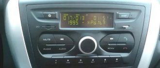
Connector pinout January 7 2
I would like to immediately convey a special greeting to the designer of AvtoVAZ, who came up with this arrangement of this block. In my opinion, I can't think of a worse place. See for yourself.
The ECU is located under the glove compartment under the passenger's feet and hidden under the upholstery. The upholstery is attached to the body on the right with a self-tapping screw.
- If your interior heater (radiator) leaks, the antifreeze will go straight to the control unit, causing almost 100% failure. Even though the Lada Granta is initially equipped with a good quality imported Visteon radiator.
- As you correctly noted, water can get in from under the hood. The rubber plugs on the Lada Granta are not of very good quality, so when they dry out, water will flow onto the controller. To prevent this from happening, check the condition of the rubber plug.
- If the drainage hole (which is shown in the video below) becomes clogged, water may flow into the cabin.
Source