Help on the fuel system of the engine 2111 VAZ 21083, 21093, 21099
The fuel system (power system) of the injection engine (2111) of VAZ 21083, 21093, 21099 cars is designed for storing, cleaning and supplying fuel and air to the engine.
In this case, the air entering the engine cylinders is cleaned by an air filter, gasoline from the fuel tank is pumped through a pipeline into the fuel rail and cleaned by the fuel filter. Excess gasoline is dumped back into the gas tank via the return line.
Help on the fuel system of the injection engine 2111 of VAZ 21083, 21093, 21099 cars
Fuel used (according to GOST 51105-97) - Premium-95 gasoline
Gas tank (fuel tank) - 21083-1101013
Gas tank capacity - 43 liters
The pressure in the fuel line created by the fuel pump is 3.2 bar
Fuel rail with injectors and fuel pressure regulator
Working pressure in the fuel rail - 284-325 kPa
Safety valve - 21214-1164080
Gravity valve - 2112-3706040
Air filter element - 2112-1109080
Tightening torques for threaded connections in the fuel injection system of VAZ 21083, 21093, 21099 cars
Fuel module mounting nuts - 1.0-1.5 N.m (0.1-0.2 kgf.m)
Fittings and nuts for hoses and fuel pipes - 20.0-34.0 N.m (2.0-3.4 kgf.m)
Fuel rail mounting bolts - 9.0-13.0 N.m (0.9-1.3 kgf.m)
Fuel pressure regulator mounting bolts - 8.0-11.0 N.m (0.8-1.1 kgf.m)
Throttle assembly mounting nuts - 14.3-23.1 N.m (1.5-2.3 kgf.m)
Nuts securing the receiver to the exhaust pipeline - 20.0-24.0 N.m (2.1-2.4 kgf.m)
Notes and additions
— More detailed information on each of the elements of the fuel injection system of VAZ 21083, 21093, 21099 cars can be found in the articles describing them by clicking on the links above.
Source
Where is the fuel filter located?
The fuel filter (TF) on the VAZ-21099i is designed to clean gasoline from debris, dirt and various impurities; it is a one-piece system with a solid iron body and a filter element inside. The frequency of its replacement is after any 20-30 thousand km of the distance traveled, also if the car begins to move jerkily, and diagnostics (the process of establishing a diagnosis, that is, a conclusion about the nature of the disease and the patient’s condition)
showed that the TF was clogged.
It is not difficult to find out where the fuel filter is located; to do this, you need to install the car on an inspection hole or a car lift. The TF is located on the bottom of the body, next to the rear support and the gas tank, and is secured with a special clamp, which is tightened with a bolt and nut.
Before you start changing the filter, you need to release the fuel pressure, otherwise, when you unscrew the fuel fittings, gasoline will spray out under enormous pressure. You can relieve pressure in the line using a special nipple located at the rear of the fuel rail. Before starting such an operation, you need to prepare a plastic container into which to pour gasoline, and then unscrew the safety cap.
To release the pressure, you can use a regular flat-head screwdriver; when you press the nipple valve, gasoline will come out of the system.
After removing the fuel from the line, we proceed to replacing the TF.
Source: avtobrands.ru
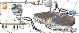
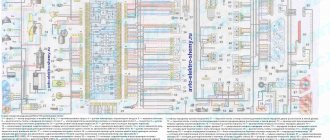
Diagram of the power supply system for the injection engine 2111 VAZ 21083i, 21093i, 210993i (EURO-2)
The power supply system for the injection engine 2111 of VAZ 21083i, 21093i, 21099i vehicles is designed to ensure uninterrupted supply of fuel to the engine cylinders. In addition, it has the functions of storing a certain supply of fuel on board the vehicle and cleaning it from mechanical contamination.
Engine power supply system diagram 2111
Elements of the power supply system for injection engines of VAZ 21083i, 21093i, 210993i cars
— The fuel tank is welded, welded from two stamped halves. Capacity 43 liters. The filler neck is located in the right rear fender of the car.
— The fuel module (electric fuel pump) is installed in the fuel tank and combines a fuel pump and a fuel level indicator sensor. To access the module, there is an inspection hatch under the rear seat in the car body. A fuel purification strainer is installed on the inlet pipe of the fuel module.
— fuel filter in a metal casing, not dismountable, is installed under the bottom of the car, next to the fuel tank.
— The fuel rail supplies fuel from the supply line to the four injectors inserted into it. The connection between the ramp and the injectors is sealed with rubber rings. At the end of the ramp there is a diagnostic fitting for measuring pressure in the system.
— An injector is an electromagnetic valve that allows fuel to flow into the cylinders when voltage is applied to it and closes when there is no power under the action of a return spring. At the end of the injector there is a nozzle through which fuel is injected into the intake manifold. The injection system controller controls the injectors.
— Fuel pressure regulator – bypass valve installed on the fuel rail. It maintains the required operating pressure in the fuel line (around 3 atmospheres). And it changes depending on the engine speed. Excess fuel is discharged back into the fuel tank via the return line.
— Separator – element of the fuel vapor recovery system (under EURO 2). Fixed under the rear right fender of the car. In it, gasoline vapors condense and return back to the fuel tank. Fuel vapors that have not had time to condense enter from the separator into the adsorber.
— Adsorber - a container (element of the fuel vapor recovery system), where fuel vapors coming from the separator are absorbed by activated carbon. When the engine crankshaft speed increases, the control unit gives a command to open the canister purge valve and gasoline vapors are sucked into the intake module receiver. Installed in the engine compartment.
— The gravity valve prevents fuel from leaking out of the fuel tank when the vehicle turns over.
— A two-way valve prevents excessive increase or vice versa decrease in pressure in the fuel tank.
Notes and additions
— Elements of the fuel vapor recovery system (separator, adsorber) are available only on VAZ 21083i, 21093i, 21099i vehicles that comply with EURO 2 standards.
Source
Diagram of the power supply system for the injection engine 2111 VAZ 21083i, 21093i, 210993i (EURO-2)
Well, if, after all, you, the reader, decide to open this necessary cart, sit comfortably on your fifth point to get at least a little pleasure)))
Perhaps the story should begin with a return to the past, or rather about the purchase of a tank. After the purchase, the tank was cleaned both inside and out. Then my favorite zincari was used...
Then we move to the garage, where we prime and paint the tank
We could have stopped at this point in pampering with the tank, but that’s not for us. I also decided to cover it with rubber mastic.
At the same time I glued rubber bands to it
Next we plug in the fuel pump with the FLS you need. Now we're done with the tank, IT'S BETTER TO TAKE A TANK WITH M6 STUDS
, they are welded through spacers, if they break off, it’s easier to attach a new one.
For clarity, we take this diagram and begin to stick tubes and hoses into it; I assembled it according to it, with the exception of the gravity valve (I decided not to stick it in).
General diagram of the VAZ 2109
The vehicle was equipped with engine 21083. Its displacement was 1.5 liters, power was measured at 79 hp. The motor is located across the engine compartment (pictured below). The history of the VAZ 2109 brand dates back to 1988. The car is a modernized analogue of the 2108 model and is distinguished by the presence of additional two doors in the rear.
The ability to fold the rear row seats, thereby expanding the trunk capacity, turns the Nine into a family car. There are also cars (mostly they belonged to the first releases) that were equipped with a 2108 engine, the displacement of which was 1.3 liters and the power was 64 hp.
Where is the fuel pump located on the VAZ-21099 injector
Removing and installing a gasoline pump (PG) is not a difficult job and does not require extensive plumbing experience or high qualifications. But if you don’t have to look for a fuel pump on carburetor cars for a long time (it is located on the engine, under the hood), then a beginner may not find it on the injector on the first try. Where is the fuel pump located on the VAZ-21099 sedan injector? Let's figure it out step by step:
- we move the front seats in the car forward as much as possible to free up space in the rear;
- open the rear left door of the car, find a small hinge on the rear sofa, which is located at the junction of the “seats” approximately in the middle of the cabin;
- pull the loop up, thereby raising the back of the lower seat;
- under the carpet we see the gas tank flap;
- unscrew the two fastening screws, remove the hatch and find the fuel pump underneath.
VAZ 2109 injector diagram: how it works
In 1997, they began producing 2109-20 cars, which are equipped with an engine with a distributed injection system (injector). This improves their efficiency, environmental and traction performance. Distributed injection is so called because fuel is injected directly into each cylinder by a separate injector.
Such a system makes it possible to somewhat reduce the toxicity of exhaust gases, as well as improve the driving performance of the 2109 car. Today, there are injection systems without feedback and with feedback. Both presented systems can include domestic and imported components. Each system has its own design, repair and diagnostic features.
I would just like to note the main principles of the design, normal operation, engine repair (if necessary) and subsequent diagnostics of the fuel injection system (the VAZ 2109 injector diagram is presented below).
The automotive fuel injection system, which has feedback, is used mainly on export VAZ 2109. The exhaust system of these cars is equipped with a catalytic converter for exhaust gases and an oxygen sensor. It provides feedback. Using an oxygen sensor, the oxygen concentration in already exhaust gases is monitored.
Next, the electronic control unit (ECU) of the vehicle, according to its signals, maintains the appropriate ratio of fuel and air, that is, one at which the special converter works extremely efficiently. The injection system, in which there is no feedback, is not equipped with a converter and an oxygen sensor.
Their function (regulating the concentration of CO in already completely exhausted gases) is performed by a CO potentiometer. They also do not use a gasoline vapor recovery system.
Content
The injector is controlled by electronic signals that come from the processor
, and he, in turn, in order to issue them, tracks signals from sensors installed on and in the engine.
The only work that can be done on an injection engine to adjust it and stabilize its operation is flushing the injector, or more precisely, flushing the injectors.
Fuel lines and fine fuel filter
Fuel lines 35 and 36 are made of leaded or galvanized steel tubes. The tubes are connected to the fuel pump and to the tank by rubber hoses in a fabric braid and secured with screw clamps. The fuel pump is connected to the carburetor by a rubber hose.
The fuel supply line 35 is made with a diameter of 8 mm, the drain line 36 with a diameter of 6 mm. In front of the fuel pump 32, a fine fuel filter 33 is installed on the hoses and secured to the hoses with screw clamps. The filter has a non-separable design with a paper filter element in a plastic housing. The plastic body and lid are welded using ultrasonic welding or high-frequency currents.
VAZ 2109 stove diagram: improvement options
The design and operation of the VAZ 2109 stove does not imply any complex procedures. However, the factory heater most often cannot distribute hot air evenly to the feet and onto the windshield. The modernization carried out on the VAZ-2114, contrary to expectations, could not solve this problem. However, there are no hopeless situations, and the presented diagram of the VAZ 2109 stove will help everyone who has the desire and time to solve this problem with their own hands.
In the process we will need:
- polystyrene foam and bitoplast;
- silicone or acrylic sealant;
- set of screwdrivers and keys;
- container for collecting coolant;
- sheet of copper or aluminum.
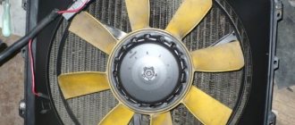
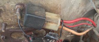
Where is the fan relay VAZ-21099 injector
Quite often a problem arises with the Ninety-Nine when the engine fan does not turn on and the coolant begins to boil. If such a malfunction occurs, first of all they check the functionality of the fan itself by applying voltage directly to it from the battery, but there may be other problems.
In order to check the entire circuit, it is important to find where the VAZ-21099 injector fan relay is located, since it is responsible for turning on the airflow. We find this part in the front of the car, on the passenger side, it is installed under the glove compartment, at the passenger’s feet.
The required relay in the picture is indicated by an orange circle, and here you will also find a fuse that blows when the cooling fan is short-circuited.
Let's get started:
- First you need to drain the coolant into a special separate container. Any liquid remaining in the radiator should be removed using a hose and funnel. Carefully remove the air ducts and, be sure to pay attention to possible misalignment of the holes that are located in the panel with the stove nozzles. If the misalignment exceeds 50%, you need to cut the interior heater.
- Next, having previously marked the connectors of the switches and light bulbs, remove the instrument panel. We disconnect the steering wheel, steering column trim and steering column switches. Next, we dismantle the heater: unscrew the 4 M10 nuts, disconnect the wire connector and all connectors on the heater body.
- Disconnect the radiator hoses and remove the heater valve cable latch. Next, carefully remove the heater, after unscrewing the two fan screws. Remove the radiator by unscrewing the three bolts. Be careful - there may still be coolant left here.
- Then make turbulators. These are special plastic spirals that increase the heat transfer of the radiator. “According to the rules,” they should be installed at the factory, but most often they are not. To make them yourself, you need to cut aluminum or copper plates, the width of which is 6 mm and the thickness is 1.5 mm. One side of such a plate should be clamped in a drill, and, at the same time, the other, using a vice, should be twisted into a spiral.
- Carefully inspect the bottom of the heater. Make sure there are no deformations, displacements, breaks or other defects. Then disassemble the stove by separating the body into two halves. To do this, use a screwdriver to open the latches and then unscrew the screw under the central nozzle. Remove the damper control levers.
- Carefully inspect the inside surface of the stove. If the foam has come loose, carefully glue it back, you can add strips of bitoplast. The housing should be made as airtight as possible. Adjust the center shutter.
- Before you begin assembling the heater, be sure to lubricate the places where the dampers are attached with a special grease. At the same time, when connecting the halves of the case, apply silicone or acrylic sealant to the connector. The heater should be assembled in the reverse order of disassembly. If there is deformation on the bottom wall, fill the gap with sealant.
- There should be no gaps between the stove body and the radiator. In the places where the housing is connected to the radiator, bitoplast should be glued. Next, you need to balance the fan impeller by winding wire around the blades. The wires must be routed through a special rubber plug located in the heater housing.
- Be sure to adjust the travel of the dampers. You need to be guided by the fact that the levers should always be clearly fixed in their extreme positions. Adjustment must be carried out by selecting the positions of the braid. Next, adjust the stove tap. You should choose a position in which the tap will not close completely.
- It is necessary to lubricate the hoses and radiator tubes with sealant before installing them. New clamps should be used. When the assembly is completed, you have filled in the coolant and warmed up the engine, you should tighten the clamps again. Before installing the instrument panel, you need to glue foam and bitoplast to the inlet holes of the nozzles.
Checking the power system
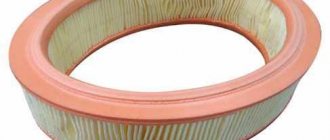
Remove the air filter housing cover by unscrewing the nut with a 10 mm wrench and unfastening the spring clips. Remove the air filter.
Unscrew the four nuts with a size 8 wrench, use a screwdriver to loosen the clamp of the crankcase ventilation hose at the connection point to the valve cover and remove the air filter housing.
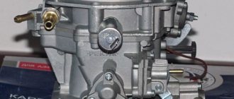
Look inside the carburetor.
The primary choke should be completely closed if the engine is cold, and fully open if the engine is warm or hot.
In the first case, open the air damper.
Press the carburetor throttle valve actuator with your hand.
If a stream of gasoline appears from the accelerator pump nozzle, then there is gasoline in the carburetor
In order to be completely sure that there is gasoline in the carburetor, it is necessary to unscrew the five screws securing the top cover of the carburetor, the screw securing the bracket for the choke control cable sheath and remove the wire from the idle speed solenoid valve.
Very carefully, without allowing lateral movements, lift the carburetor cover.
The gasoline level should be approximately 22–23 mm below the connector of the carburetor cover and body
Place the carburetor cover in place and tighten it with 2-3 screws diagonally.
Get behind the wheel, smoothly pressing the gas pedal, turn on the starter and start the engine.
Replace the carburetor cap without securing it. Carefully insert the screwdriver into the connector of the cover and housing.
Try manually pumping gas. If it fails, turn the crankshaft a little with the starter and try again.
If the carburetor begins to intensively fill with gasoline, put the carburetor cover in place and press it with 2-3 screws diagonally. Try starting the engine.
If the engine starts, the carburetor needle valve hangs.
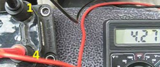
Where is the temperature sensor located?
If the temperature sensor does not show on the instrument panel, there is a high risk of overheating the engine, since the instrument panel does not inform the driver about the heating of the internal combustion engine coolant. Of course, the instrument panel or electrical wiring may be faulty, but most often the temperature sensor (DTOZH) on the engine itself refuses to work.
Where is the temperature sensor located on an injection car 099? Of course, you need to look for it in the engine compartment:
- open the hood;
- we find the wiring that is located between the rear of the engine valve cover and the air filter housing;
- where the DTOZH is located can be seen in more detail in the following photos.
Electrical diagram of VAZ 2109: required reading
“Nines” are one of the most popular domestic front-wheel drive cars in Russia. They are inexpensive and relatively easy to repair. Often they are serviced by the owners themselves, vehicles are tuning items, they turn into a hobby for their owners. Owners install new equipment on their cars. The electrical circuit diagrams below will be very useful during repairs.
The VAZ 2109 electrical diagram will always help car owners check which instruments and devices are out of order. To find out, you need to check them with a “tester”. Having identified any problems, you can repair the machine yourself.
The first VAZ 2109 models were produced with a carburetor engine. However, the global industry has long mastered a new type of fuel supply - injection. Therefore, the transition to a new type of fuel supply with electronic regulation was technically justified. As a result of the development, the injector electrical circuit used by the VAZ 2109 made it possible to improve the performance characteristics of the vehicle.
Where is the starter relay located?
Just like the engine cooling fan, the starter is controlled by a relay, and its malfunction can cause problems:
- when you turn the ignition key, nothing happens, the engine does not show any signs of life;
- When I try to start the engine, clicks are heard, but the starter does not crank.
Finding out where the starter relay is located on a VAZ-21099i car is very simple; to do this, you just need to open the hood of the car and look behind the air pipe of the injection engine; the part you are looking for is shown below in the picture.
What is an injector
The VAZ 21093 car has an injector, the electrical circuit in the device allows, through an electronic control system, to start and optimize engine operation. The main element of the new supply was the injection of a combustible mixture into the combustion chamber under pressure. In carburetor-type engines, the flow of the combustible mixture occurred under vacuum.
In order to ensure optimization of the operation of the VAZ 2109 injector engine, the electrical circuit is designed in such a way that through the ECU - an electronic control unit - a full range of control is carried out and the process is carried out from the supply of fuel to the emission of exhaust gases.
Car VAZ 2109 injector wiring diagram includes:
- electronic fuel injection system;
- electronic ignition system;
- system for monitoring the state of fuel supply, combustion and gas emissions.
At the same time, there are still reserve connectors in the block, allowing you to connect additional sensors for monitoring the operating status of the mechanisms. Such options include an anti-theft device, a knock sensor and others.
On a VAZ 2109 car, the injector electrical circuit is designed in such a way that the engine is controlled through the ECU. The system completely controls the fuel combustion process through it.
An injector installed on a VAZ 21093 car, the electrical circuit of which includes a block of a new type ECU type 2114-3722010-60. The unit is characterized by the use of new knife-shaped fuses. They have a large impact area, as a result of which the reliability of the unit is increased. The ECU unit has information and control connections through sensors and control of actuators. It controls the process and sends a signal to the control panel about the operating status of the following components:
- fuel tank and fuel line;
- fuel pump;
- fuel mixture pressure regulator;
- ramps and injectors;
- throttle valve;
- filters and valves on the fuel return line.
All these nodes are connected to a single unit, and if any sensor fails, the system will receive incomplete information and may refuse to start the engine. However, of course, the VAZ 2109 electric injector circuit will not start if the main DPKV device - the crankshaft position sensor - fails. Until it sends a start signal to the ECU, the unit will not give a command to receive a spark from the spark plugs.
Malfunctions of VAZ 21099 - the injector also fails!
Regardless of the time of year outside, very often the car may simply stop starting, or begin to respond poorly to the gas pedal. In this case, all on-board computer sensors may not show errors. The causes of failure should be sought in the injector.
Usually the breakdown is associated with clogging of the fuel injector nozzles, which increases fuel consumption in the car and reduces traction. Due to the fact that the fuel does not enter in the quantity required for engine operation, the idle speed begins to float. For a VAZ, the normal value when the engine is idling in warm weather is 900 rpm. When starting in the cold season, the engine produces 1500 rpm; with proper operation, after 5–10 minutes they should drop to 900.
It is also worth paying attention to the throttle valve of the intake manifold - over time, black deposits appear on it, which prevents it from properly passing air. It is enough to clean the damper with a special spray and gently wipe with a cloth - the problem is eliminated!
Removal and replacement
Now we’ll talk specifically about how to properly remove and replace old injectors that have lost their usefulness with new units.
The process of dismantling each of the 4 injectors is identical, so there will be no difference in the process.
Perhaps the most problematic step in replacing or cleaning injectors is dismantling the fuel rail. Therefore, we will separately tell you how this knot is removed.
The fuel rail is the bar on which the injectors are mounted. It is secured with a pair of bolts on the intake pipe. To the left of the ramp there is a fuel pressure control fitting. To remove it you need:
Please note that under the fuel rail mounting bolts there are washers that must be returned to their place during reassembly or replaced with similar new ones.
The engine will not start
It is noted that the VAZ 21093 injector, the electrical circuit includes a lot of electronics. Due to its failure, the car may not start only if the DPKV fails. In other cases, the motor will work, but there will be various malfunctions, the causes of which should be sought. If the sensor is working properly, then you should use the classic method of troubleshooting in equipment - there is nothing to burn or nothing to set on fire.
In this case, first of all, the starting system is checked, the serviceability of the spark plugs and then the fuel supply. Details about step-by-step checking of the serviceability of vehicle components are written in the operating manual.
When replacement is required
There are several signs that indicate you need to at least remove and check the condition of the fuel injectors. Next, a decision is made to clean or replace the elements.
Pay attention to the behavior of your car and specifically the engine. They will tell you if there is something wrong with the injectors. This may manifest itself as follows:
Do not rush to purchase new injectors right away, since cleaning old ones often restores their functionality and returns them to their previous stable functionality.
Source