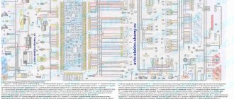
The VAZ-2112 car was produced at AvtoVAZ from 1998 to 2009, in Ukraine from 2009 to 2014. The following are color wiring diagrams (injector and carburetor) with a description of all elements for various modifications. The information is intended for self-repair of cars. Electrical circuits are divided into several blocks for ease of viewing via a computer or smartphone; there are also circuits in the form of a single picture with a description of the elements - for printing on a printer in one sheet.
To diagnose and repair yourself, first look to see if everything is okay with the generator. Is it put on well and does not sag? This procedure must be done with all versions of the fuel system, both carburetor and injection.
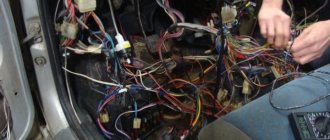
We check the fuses according to the electrical diagram. The reverse side of the safety block cover will also be of great help. There are clues there that the diagram will help you decipher.
Replace the burnt out element and try to start the car again. You need to check whether the battery terminals are tightly connected and whether they are oxidized. Is the wire going from the battery to the generator and to the starter damaged?
Design of the power supply system for the injection engine VAZ 2110, VAZ 2111, VAZ 2112, Lada Ten
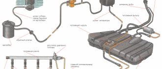
Fuel supply diagram for an engine with a fuel injection system
1 – injectors 2 – fitting plug for monitoring fuel pressure 3 – injector ramp 4 – bracket for fastening fuel pipes 5 – fuel pressure regulator 6 – canister with solenoid valve 7 – hose for sucking gasoline vapors from the canister 8 – throttle assembly 9 – two-way valve 10 – gravity valve 11 – safety valve 12 – separator 13 – separator hose 14 – fuel tank plug 15 – filler pipe 16 – filler pipe hose 17 – fuel filter 18 – fuel tank 19 – electric fuel pump 20 – fuel drain line 21 – fuel supply line
Fuel is supplied from a tank installed under the bottom in the rear seat area. The fuel tank of the VAZ 2111 is made of steel and consists of two stamped halves welded together. The filler neck is connected to the tank with a gas-resistant rubber hose secured with clamps. The plug is sealed. The fuel pump is electric, submersible, rotary, two-stage, installed in the fuel tank. The developed pressure is at least 3 bar (3 atm).
The VAZ 2110 fuel pump is turned on at the command of the injection system controller (with the VAZ 2112 ignition on) via a relay. To access the pump, there is a hatch under the rear seat in the bottom of the car. From the pump, fuel under pressure is supplied through a flexible hose to the fine filter and then through steel fuel lines and rubber hoses to the fuel rail.
The fine fuel filter is non-separable, in a steel housing, with a paper filter element. There is an arrow on the filter housing that must coincide with the direction of fuel movement.
The fuel rail serves to supply fuel to the injectors and is mounted on the intake manifold. On one side there is a fitting for monitoring the fuel pressure, on the other there is a pressure regulator. The latter changes the pressure in the fuel rail - from 2.8 to 3.2 bar (2.8-3.2 atm) - depending on the vacuum in the receiver, maintaining a constant difference between them. This is necessary for accurate dosing of fuel by injectors.
The fuel pressure regulator VAZ 2111, VAZ 2112 is a fuel valve connected to a spring-loaded diaphragm. The valve is closed under the action of the spring. The diaphragm divides the regulator cavity into two isolated chambers - “fuel” and “air”. The “air” is connected by a vacuum hose to the receiver, and the “fuel” is connected directly to the ramp cavity. When the engine is running, the vacuum, overcoming the resistance of the spring, tends to retract the diaphragm, opening the valve. On the other hand, fuel presses on the diaphragm, also compressing the spring. As a result, the valve opens and part of the fuel is released through the drain pipe back into the tank. When you press the gas pedal, the vacuum behind the throttle valve decreases, the diaphragm, under the action of a spring, closes the valve - the fuel pressure increases. If the throttle valve is closed, the vacuum behind it is maximum, the diaphragm pulls the valve harder - the fuel pressure decreases. The pressure difference is set by the spring stiffness and the size of the valve opening and cannot be adjusted. The pressure regulator is non-separable; if it fails, it is replaced.
The injectors are attached to the ramp through rubber sealing rings. The injector is an electromagnetic valve that allows fuel to pass through when voltage is applied to it, and closes under the action of a return spring when there is no power. At the injector outlet there is a nozzle through which fuel is injected into the intake manifold. The injection system controller controls the injectors. If there is a break or short circuit in the injector winding, it should be replaced. If the injectors become clogged, they can be washed without dismantling at a special service station.
The feedback injection system uses the VAZ 2110 fuel vapor recovery system. It consists of an adsorber installed in the engine compartment, a separator, valves and connecting hoses. Fuel vapor from the tank partially condenses in the separator, and the condensate is drained back into the tank. The remaining vapor passes through gravity and two-way valves. The gravity valve prevents fuel from leaking out of the tank when the VAZ 2111 car rolls over, and the two-way valve prevents excessive increase or decrease in pressure in the fuel tank.
Then the fuel vapors enter the VAZ 2110 adsorber, where they are absorbed by activated carbon. The second fitting of the adsorber is connected by a hose to the throttle assembly, and the third to the atmosphere. However, when the engine is turned off, the third fitting is closed by an electromagnetic valve, so that in this case the adsorber does not communicate with the atmosphere. When the engine starts, the injection system controller begins to send control pulses to the valve with a frequency of 16 Hz. The valve communicates the adsorber cavity with the atmosphere and the sorbent is purged: gasoline vapors are sucked through the hose into the receiver. The greater the engine's air consumption, the longer the duration of the control pulses and the more intense the purging.
In an open-loop injection system, the fuel vapor recovery system consists of a separator with a two-way check valve. The VAZ 2111 air filter is installed in the front left part of the engine compartment on three rubber holders (supports). The filter element is made of paper; when installing, its corrugations should be located parallel to the axis of the car. After the filter, the air passes through the mass air flow sensor and enters the intake hose leading to the throttle body. The throttle assembly is fixed to the receiver. By pressing the gas pedal, the driver slightly opens the throttle valve, changing the amount of air entering the engine, and therefore the combustible mixture - after all, the fuel supply is calculated by the controller depending on the air flow. When the engine is idling and the throttle valve is closed, air flows through the idle air control valve, a valve controlled by the controller. The latter, by changing the amount of supplied air, maintains the idle speed specified (in the computer program). The idle speed regulator of the VAZ 2112 is non-separable; if it fails, it is replaced.
How to clean the injectors of a VAZ 2107
Methods for cleaning sprayers may vary; the use of one method or another depends on the level of contamination of the holes and the nature of the deposits. If you carry out preventive cleaning or remove light contamination, you can use special chemicals, the use of which does not involve removing the injectors.
If the injectors are in a neglected state and cleaning with additives does not make sense, then you will have to dismantle the injector and replace the VAZ 2107 injectors.
Cleaning injectors with additives
Additives can not only remove deposits from fuel nozzles, but also clean the fuel system as a whole. This method is effective only with the systematic use of cleaning chemicals. Additives need to be used every 17-20 thousand kilometers. To clean, the standard fuel pump is turned off, and the fuel injection line is connected to a container through which the cleaning liquid is supplied under pressure.
The engine is started and idles for a quarter of an hour, after which it is turned off for the same amount of time. During this time, the deposits become soft. The engine is then started again, but this time the speed is gradually increased to maximum to remove sludge fragments. In this mode, the internal combustion engine should operate for about half an hour.
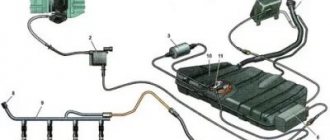
Fuel supply diagram for an engine with a fuel injection system
1 – nozzles; 2 – fitting plug for monitoring fuel pressure; 3 – injector ramp; 4 – bracket for fastening fuel pipes; 5 – fuel pressure regulator; 6 – adsorber with solenoid valve; 7 – hose for suction of gasoline vapors from the adsorber; 8 – throttle assembly; 9 – two-way valve; 10 – gravity valve; 11 – safety valve; 12 – separator; 13 – separator hose; 14 – fuel tank plug; 15 – filling pipe; 16 – filling pipe hose; 17 – fuel filter; 18 – fuel tank; 19 – electric fuel pump; 20 – fuel drain line; 21 – fuel supply line.
Fuel is supplied from a tank installed under the bottom in the rear seat area. The fuel tank is made of steel and consists of two stamped halves welded together. The filler neck is connected to the tank with a gas-resistant rubber hose secured with clamps. The plug is sealed.
The fuel pump is electric, submersible, rotary, installed in the fuel tank. The developed pressure is at least 3 bar (300 kPa).
The fuel pump is turned on at the command of the injection system controller (with the ignition on) through a relay. To access the electrical connector of the pump, there is a hatch under the rear seat in the bottom of the car. From the pump, fuel under pressure is supplied through a flexible hose to the fine filter and then through steel fuel lines and rubber hoses to the fuel rail.
The fine fuel filter is non-separable, in a steel housing, with a paper filter element. There is an arrow on the filter housing that must coincide with the direction of fuel movement.
The fuel rail serves to supply fuel to the injectors and is mounted on the intake manifold. On one side there is a fitting for monitoring the fuel pressure, on the other there is a pressure regulator. The latter changes the pressure in the fuel rail - from 2.8 to 3.2 bar (280-320 kPa) - depending on the vacuum in the receiver, maintaining a constant difference between them. This is necessary for accurate dosing of fuel by injectors.
The fuel pressure regulator is a fuel valve connected to a spring-loaded diaphragm. The valve is closed under the action of the spring. The diaphragm divides the regulator cavity into two isolated chambers - “fuel” and “air”. The “air” is connected by a vacuum hose to the receiver, and the “fuel” is connected directly to the ramp cavity. When the engine is running, the vacuum, overcoming the resistance of the spring, tends to retract the diaphragm, opening the valve. On the other hand, fuel presses on the diaphragm, also compressing the spring. As a result, the valve opens and part of the fuel is released through the drain pipe back into the tank. When you press the gas pedal, the vacuum behind the throttle valve decreases, the diaphragm, under the action of a spring, closes the valve - the fuel pressure increases. If the throttle valve is closed, the vacuum behind it is maximum, the diaphragm pulls the valve harder - the fuel pressure decreases. The pressure drop is determined by the spring stiffness and the size of the valve opening; cannot be adjusted. The pressure regulator is non-separable; if it fails, it is replaced.
The injectors are attached to the ramp through rubber sealing rings. The injector is an electromagnetic valve that allows fuel to pass through when voltage is applied to it and closes under the action of a return spring when there is no power. At the injector outlet there is a nozzle through which fuel is injected into the intake manifold. The injection system controller controls the injectors. If there is a break or short circuit in the injector winding, it should be replaced. If the injectors become clogged, they can be washed without dismantling at a special service station.
The closed-loop injection system uses a fuel vapor recovery system. It consists of an adsorber installed in the engine compartment, a separator, valves and connecting hoses. Fuel vapor from the tank partially condenses in the separator, and the condensate is drained back into the tank. The remaining vapor passes through gravity and two-way valves. The gravity valve prevents fuel from leaking out of the tank when the vehicle rolls over, and the two-way valve prevents excessive increase or decrease in pressure in the fuel tank.
Then the fuel vapor enters the adsorber, where it is absorbed by activated carbon. The second fitting of the adsorber is connected by a hose to the throttle assembly, and the third is connected to the atmosphere. However, when the engine is turned off, the third fitting is closed by an electromagnetic valve, so that in this case the adsorber does not communicate with the atmosphere. When the engine starts, the injection system controller begins to send control pulses to the valve with a frequency of 16 Hz. The valve communicates the adsorber cavity with the atmosphere and the sorbent is purged: gasoline vapors are sucked through the hose into the receiver. The greater the engine's air consumption, the longer the duration of the control pulses and the more intense the purging.
In an open-loop injection system, the fuel vapor recovery system consists of a separator with a two-way check valve. The tube connecting the tank to the atmosphere is led into the cavity of the rear right wing.
The air filter is installed in the front left part of the engine compartment on three rubber holders (supports). The filter element is paper.
After the filter, the air passes through the mass air flow sensor and enters the intake hose leading to the throttle body.
The throttle assembly is fixed to the receiver. By pressing the gas pedal, the driver slightly opens the throttle valve, changing the amount of air entering the engine, and therefore the combustible mixture, because the fuel supply is calculated by the controller depending on the air flow. When the engine is idling and the throttle valve is closed, air flows through the idle air control valve, a valve controlled by the controller. By changing the amount of supplied air, the controller maintains the idle speed specified (in the computer program). The idle speed regulator is non-separable; if it fails, it is replaced.
Signs and Symptoms of a Malfunctioning Fuel Pressure Regulator
- the engine stalls at idle;
- engine power is greatly reduced;
- when accelerating, it is not possible to achieve normal dynamics;
- the car reacts poorly to pressing the gas pedal;
- fuel consumption suddenly increases greatly;
- the amount of carbon dioxide emissions increases;
- the crankshaft rotation speed changes.
All these problems arise due to the fact that the regulator becomes clogged or completely clogged over time. Another common cause of failure is weakening of the spring, leading to a strong decrease in pressure. In the absence of normal pressure, fuel supply decreases, power decreases and controllability deteriorates. Such problems are especially common on Ladas - Kalina and Priora, as well as on cars of the 2110, 2112, 2114, 2115 series.
To check the part, you need to carefully inspect it itself, the vacuum hose and all connections. Any leaks found must be corrected. It is also recommended to check the membrane. Disconnect the tube that goes from the RTD to the receiver and shake it. If no gasoline comes out from inside and there is no strong odor, then the membrane is in order.
RTD in diesel engines
Diesel vehicles running on the Common Rail system are also equipped with a pressure regulator. It fits into the fuel rail or is located on the high pressure fuel pump housing. The principle of operation is approximately the same. A special valve diverts unused fuel into the return line, preventing excessive loading.
In diesel engines, the regulator has a slightly different structure than in gasoline engines. It consists of a solenoid and a rod, which rests against a ball to shut off the return line. The design protects the engine from hydraulic vibrations and, as a result, from rapid wear.
VAZ 2110 engine 8 valves, design of the “tens” injection engine, power circuit
The VAZ 2110 8-valve engine became the first power unit to appear on the “top ten”. At first it was a carburetor engine, which differs little from the 08 engine, which we will talk about today, and then they mastered the production of the VAZ 2110 with an 8-valve injection engine. The device of which we will also consider.
In total, during the production of the “ten”, three 8-valve engines were under the hood of this car. This is a carburetor with a volume of 1.5 liters, an injector of the same volume and an 8-valve injector, but with a volume of 1.6 liters. These are engine models 2110, 2111 and 21114 respectively. The main difference between the 1.5 and 1.6 liter engines is the increased piston stroke from 71 to 75.6 mm, due to which the volume increased. At the same time, the cylinder diameter remained the same 82 mm. The height of the cylinder block and the crankshaft configuration have increased.
To begin with, we will take a detailed look at the structure of the VAZ-2110 engine with a carburetor power system, so that we can then clearly understand the differences between the injection version of the VAZ 2110 8-valve engine and the carburetor version. So, pay attention to the picture, just below.
The “tens” unit differed from the 08 engine only in the presence of an original camshaft. Otherwise, the layout is almost the same as on the G8, the same components and parts. For convenience, everything in this picture is numbered.
Signs of breakdown
There are several situations in which the pump or its components can be at fault. This will definitely have to be checked. Otherwise, you can spend a lot of money buying and installing a new fuel pump, but in the end it turns out that the problem is completely different.
- The engine will not start. This is not a clear sign of problems with the pump, but still. Therefore, first check the condition of the spark plugs, the presence of a spark, and the absence of traces of oil on them. Also check the electronic control unit.
- Pressure inside the fuel system. If the pump is operating normally, it will create a pressure of 3.2 bar. Depending on the type of engine in your VAZ 2114, the characteristics may differ slightly: For a 1.5-liter engine, the optimal values are 285-325 kPa;
- For a 1.6-liter engine, these characteristics in optimal operating mode will range from 375 to 390 kPa.
There is no signal that is not sent to the pump. This happens when you turn the ignition key. During normal operation, the pump begins to vibrate slightly when turning the key. If this does not happen, be sure to check the wiring. Troubles the power unit. This is also not an ideal sign of a fuel pump failure. But you still have to check. It is likely that the culprit in this situation will be the pump. The engine jerks. Moreover, this happens at low speeds or even at start. There are two possible reasons for the situation - a breakdown of the pump itself or a problem with the fuel pump grid, which will have to be replaced.
New and old coarse filter
We recommend: How to get rid of an air lock in the cooling system?
Many people purchase the entire fuel module assembly at once, which includes a filter, sensor, float, intake chamber and the pump itself. Such a purchase will cost approximately 3,000 rubles. It is much more profitable and practical to buy a separate pump, which costs up to 1000 rubles. This is due to the fact that when the pump fails, the remaining elements almost always remain intact and are fully suitable for further use.
Engine structure VAZ 2110 8 valves, carburetor
1 – generator drive pulley (damper); 2 – oil pump; 3 – toothed pulley of the coolant pump; 4 – connecting rod; 5 – piston pin; 6 – tension roller; 7 – camshaft toothed pulley; 8 – front cover of the timing mechanism drive; 9 – timing belt; 10 – rear cover of the camshaft drive; 11 – camshaft oil seal; 12 – cylinder head cover; 13 – camshaft; 14 – front cover of camshaft bearings; 15 – oil separator mesh for the crankcase ventilation system; 16 – rear cover of camshaft bearings; 17 – oil filler cap; 18 – fuel pump; 19 – ignition distributor; 20 – housing of auxiliary units; 21 – outlet pipe of the cooling jacket; 22 – pusher; 23 – valve spring; 24 – coolant temperature sensor; 25 – valve; 26 – cylinder head; 27 – cylinder block; 28 – piston; 29 – flywheel; 30 – crankshaft rear oil seal holder; 31 – rear crankshaft oil seal; 32 – crankshaft; 33 – main bearing cover; 34 – oil pan; 35 – oil pump receiver; 36 – connecting rod cover; 37 – front crankshaft oil seal; 38 – crankshaft toothed pulley; 39 – oil pan drain plug; 40 – oil filter; 41 – coolant pump; 42 – exhaust manifold; 43 – intake manifold; 44 – carburetor; 45 – valve adjusting washer; 46 – crankcase ventilation hose; 47 – valve holder; 48 – valve guide; 49 – oil dipstick.
The main difference between the VAZ 2110 injection engine is 8 valves in the power system, which is much more complicated, but this has its advantages. The injection engine is more economical, more powerful, works better and more stable. However, such an engine requires diagnostic equipment for maintenance, without which it can be extremely difficult to identify poor operation of the power unit.
VAZ 2110 engine power supply diagram 8 valves injector
The power supply system of an injection engine with 8 valves (these are engines 2111 1.5 liters and 21114 1.6 liters) consists of the following elements. Let's look at the image below.
Sealed tank with built-in electric fuel pump, which constantly provides the required pressure in the rail. The ramp contains injectors that inject fuel into the engine. In this case, the process is controlled by electronics, which sends a pulse to the injector solenoid valve, it opens and fuel is injected into the combustion chamber, and due to a mechanical return spring, the injector closes, cutting off the fuel supply. The pressure created in the injector fuel system is about 3 atmospheres. Actually, without this, not a single injection engine will work, especially if the fuel system is not sealed.
It is worth noting that the VAZ 2110 injection engine has 8 valves , among other things, there are a number of sensors, without which stable operation of the engine is not possible, these are an oxygen concentration sensor, a mass air flow sensor, a throttle position sensor. Data from the sensors is constantly transmitted to the engine control unit, which is a computing module programmed for a specific engine operating mode. It is this block that determines when and how much fuel needs to be injected into the internal combustion chambers of the engine. Some craftsmen even reprogram this unit, making the VAZ-2110 engine more powerful, but such a unit at the same time becomes more voracious.
How to check on foreign cars and VAZs
To determine a breakdown, the following procedures are performed:
- The fitting plug is unscrewed - the element that controls the fuel pressure.
- The sealing ring is inspected; if the ring is damaged, this component must be replaced.
- The spool is removed from the fitting.
- The engine is started using a pressure gauge and the pressure in the regulator is measured.
- The information obtained is compared with that specified by the manufacturer.
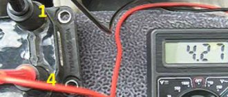
operability You can check the RTD yourself, and without even tools. To do this, it is enough to either pinch, disconnect the valve and examine the intensity of the pressure gauge. jet will give a more accurate result. It should be connected between the fitting and the fuel hose, having first disconnected the vacuum hose. The measurement is performed at idle speed. The obtained model information depends on the car - for example, in a VAZ 2110, the pressure indicator should start at 0.3 and gradually increase to 0.7 Regulator.
Fuel pressure bar with connected pressure gauge
has it changed? not Pressure You may have connected the pressure gauge incorrectly. connection Check. If everything is correct, it means the regulator has become unusable.
Repair manual for VAZ 2110, 2112, 2111 (Lada 110)
The power supply system includes elements of the following systems:
– a fuel supply system, including a fuel tank, a fuel pump, a pressure regulator, a fuel filter, a ramp with injectors, hoses and pipelines;
– an air supply system, which includes an air filter, an air supply pipe, a throttle assembly;
– a fuel vapor recovery system consisting of an adsorber and connecting pipelines.
The functional purpose of the fuel supply system is to ensure the supply of the required amount of fuel in all operating modes.
4.17. Engine fuel supply system mod. 2111 and 2112: 1 – fitting plug for monitoring fuel pressure; 2 – injector ramp; 3 – bracket for fastening fuel pipes; 4 – fuel pressure regulator; 5 – fuel pump; 6 – fuel filter; 7 – fuel drain line; 8 – fuel supply line; 9 – nozzles
Design of the motor power supply system mod. 2111 and 2112 (Fig. 4.17) differs from the power supply system for mod. 21114 and 21124 (Fig. 4.18) in that the latter do not have a return fuel line, since the pressure regulator is installed directly in the gas tank in the fuel pump module. In addition, for connecting elements of the fuel line on engines mod. 21114 and 21124 use special clamping tips instead of threaded fittings, the shape and design of the fuel rail are changed, new injectors are used, and the pressure is increased.
4.18. Engine fuel supply system mod. 21114 and 21124: 1 – fitting plug for monitoring fuel pressure; 2 – injector ramp; 3 – fuel pump module; 4 – fuel filter; 5 – tee; 6 – fuel supply line; 7 – nozzles
Troubleshooting
No pressure in the fuel rail? Causes:
- Clogged fuel filter;
- Clogged fuel pump filter;
- Fuel pump malfunction;
- Malfunction of the fuel pressure regulator (FPR). And with high blood pressure too.
If the pressure in the fuel rail gradually drops, the cause may be:
- leaking fuel pump connections;
- leaking injectors;
- fuel pump malfunction.
Let's check it like this. We clamp the leading rubber hose of the fuel rail:
- the pressure has become stable - the fuel module is leaking or the pump is faulty;
- the pressure drops - the injector(s) are leaking.
Checking the RTD. Connect the pressure gauge hose to the outlet fitting of the fuel pump and turn on the ignition:
the pressure is low but stable - this means the RTD is faulty and is releasing pressure too intensely.
If the pressure in the fuel rail is within normal limits, we look for the causes of engine malfunctions elsewhere.
Modern cars are equipped with electronic fuel pumps; mechanical ones are found only in cars manufactured before 2000. The task of this component is to ensure an uninterrupted supply of fuel. Everything functions well at high engine speeds, but problems arise when moving to low and idle speeds. Increased pressure damages fuel supply hoses and other system components. The fuel pressure regulator protects against such consequences. If there are malfunctions in it, this can be determined by several signs.
Diagram of the fuel system of the 16-valve injection VAZ-2112
The fuel system is one of the most important components in any car. After all, without it it is simply impossible to imagine the full operation of the vehicle. And so that you can imagine what the fuel system on your VAZ-2112 consists of, below we will present you with its detailed diagram, with a detailed description of each of the main elements.
Recommendations
Every car enthusiast can do a lot to extend the life cycle of all elements of the unit in question. To ensure that your car's power system works flawlessly, use the following recommendations:
- Refuel only at approved gas stations.
- Replace fuel and air filters in a timely manner.
- Use cleaning additives with caution.
- Try not to drive on a half-empty gas tank, especially in winter.
Detailed diagram of the fuel system
Detailed diagram of the fuel system.
1 — nozzles; 2 — fitting plug for monitoring fuel pressure; 3 — injector ramp; 4 — bracket for fastening fuel pipes; 5 — fuel pressure regulator; 6 — adsorber with solenoid valve; 7 — hose for suction of gasoline vapors from the adsorber; 8 — throttle assembly; 9 - two-way valve; 10 - gravity valve; 11 - safety valve; 12 - separator; 13 — separator hose; 14 — fuel tank plug; 15 - filling pipe; 16 — filling pipe hose; 17 — fuel filter; 18 — fuel tank; 19 — electric fuel pump; 20 — fuel drain line; 21 - fuel supply line.
Below we will look at the main elements of the fuel system separately.
Fuel tank
Dismantled VAZ-2112 gas tank.
The filled gasoline is supplied from the tank, which is located in the rear of the car, in the area where the sofa is located . The tank is made of steel and assembled by welding two stamped parts. Gasoline is supplied to the tank through a special neck, from a gas-resistant hose made of rubber, secured together with clamps.
Gasoline pump
Fuel pump VAZ-2112 1139009
A gas pump is an electrical functional device, submersible, installed directly into the gas tank itself. This pump is started by a signal from the ECU controller, which is responsible for fuel injection, through a relay when the ignition is turned on. If the fuel pump doesn't pump, the engine won't start! The operating pressure of the pump is at least 2.8-3 bar (atmospheres - approx.). In order to get to it, just lift the rear sofa and unscrew the technical hatch.
Fine filter
The new filter is ready for installation.
From the fuel pump, through a flexible steel hose, gasoline passes under pressure to the fine filter. The filter is made of steel and cannot be disassembled. A special paper filter element is installed inside. On the housing cover there is a special arrow, created for visual indication during installation, showing the direction of movement of gasoline in the system.
Fuel rail
Through steel fuel pipes, after filtration, gasoline passes directly to the fuel rail. It is designed to transfer gasoline to atomization and is mounted on the “outlet”. On one side of the fuel rail there is an RTD, on the other there is a fitting for controlling gasoline pressure. The pressure in the ramp in operating condition should be from 2.8 to 3.2 bar ( 2.8-3.2 atmospheres - approx.) - this indicator depends on the stabilization in the receiver, indicating constant differences in them. This is necessary in order to dose the optimal amount of gasoline into the injectors.
Fuel pressure control
Be careful when dismantling.
An RTD is a special device with a valve, assembled with a special diaphragm with a spring retainer. Under the influence of this element, the working position is in the locked type. It is also designed to divide the internal space of the regulator itself into two closed cavities - air and fuel.
The cavity for air is connected to the hose and receiver, and for fuel it is connected to the structure itself on the ramp.
During operation of the motor, the vacuum overcomes the resistance created by the spring and tries to tighten the diaphragm, thereby opening the valve. And from another position, at this time, gasoline presses on the diaphragm, also influencing the spring. As a result of this action, the valve opens slightly and part of the fuel flows back into the gas tank through the fuel line.
When the gas is pressed, the vacuum behind the throttle valve (throttle valve - approx.) becomes less, and the diaphragm, under the influence of a spring, closes the valve, increasing the fuel pressure. And if it is closed, the vacuum pulls the valve as far as possible - reducing fuel pressure.
The total pressure drop in the sensor is determined by the stiffness of the spring and the size of the hole. It cannot be adjusted, it is a non-separable element, and when it fails it must be replaced.
Fuel rail with injectors
An injector is a special solenoid valve that is needed to transfer gasoline to the manifold when current is applied to it, and close under the influence of a return spring when the power is turned off. They are mounted in place of fixation through special rubber rings and held there with a metal bracket. It is controlled by the ECU from the injection system. If a break or short circuit occurs in the injection wiring, the injectors should be replaced.
Injection system
An injection system in which feedback is provided and a fuel evaporation trap is installed. It consists of an adsorber, a separator, connection hoses and valves mounted under the hood. Its action is as follows:
- Some of the fuel vapor that accumulates in the tank is condensed in the separator and then drained back into the tank. And the rest pass through two-way and gravity valves.
- A two-way valve prevents excessive decrease and increase in pressure inside the fuel tank, and a gravity valve prevents fuel from leaking out when the vehicle rolls over.
Vapor recovery system
This is what the adsorber looks like on a VAZ-2112.
Afterwards, fuel vapors go through one fitting into the engine compartment - namely into the adsorber, where coal is installed to absorb them. The second fitting of the adsorber is connected to the throttle units using a tube, and the third is directly connected to the atmosphere. However, when the engine is not running, the 3rd fitting is closed by a valve and in this state the remaining elements are not associated with air. And when starting the engine, the controller of the system responsible for injection sends a signal to the valves with a frequency of 15-16 Hz , communicating the adsorber itself with the atmosphere. During such work, if the air flow rate is higher and the intensity of the pulses passes through more, then the blowing will be much more efficient.
And where this feedback does not exist, fuel vapors are “caught” only by a separator and one check valve.