Every more or less experienced motorist certainly knows that, depending on the type of power supply, cars can run on gas, gasoline and diesel fuel. If with the first system everything is relatively simple - gas fuel from a cylinder is sent directly to the injectors and injected into the engine, then with gasoline and diesel power systems things are much more complicated. Considering the high relevance of their consideration, our resource decided to devote a full-fledged article to this topic. In the material presented below, anyone can find information about how the power systems of diesel and gasoline units are designed and operated. Interesting? Then be sure to read everything to the end.
Node device
Oddly enough, the layout of the diesel fuel system is very similar to its gasoline counterparts. The only difference is the injection system. But more on that a little later, but for now let’s look at the design of this unit.
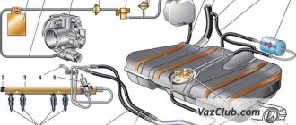
So, the fuel system diagram assumes the presence of the following structural elements:
- Gas tank. This element can be made of thin sheet steel or very dense polypropylene. On cars and SUVs, the gas tank is installed on the bottom. On trucks, in particular truck tractors, it is mounted on special supports between the rear and front axles (on the left or right side). The fuel tank has a valve that prevents fuel from leaking when the vehicle rolls over.
Filler cap. This part has a special thread that allows air to enter when unscrewing it. And to make it convenient for the driver to unscrew the cover, it has a special ratchet mechanism. This element also contains a safety valve, which, if the car gets into an accident, relieves the pressure inside the tank. By the way, on modern cars with Euro-2 or higher exhaust standards, fuel vapors are not allowed to enter the atmosphere. Therefore, to catch them, a special carbon adsorber is installed in the system.- Fuel pump. This element is electrically driven and is located inside the tank. The pump is controlled by an electronic control unit. The part is activated using a special relay. When the driver turns on the ignition, it works for some time (no more than 4-5 seconds), thereby providing the necessary pressure in the system to start the engine. It is also worth noting that the pump is cooled by gasoline. Therefore, working with an empty tank can damage it.
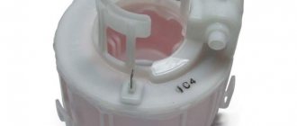
- Fuel filter. Often a car is equipped with two types of these elements. This is a mechanism for fine and coarse fuel purification. The strainer is mounted on the fuel pump housing. The essence of its work is to trap contaminants that can enter the engine and form excess carbon deposits. Also, a working filter significantly increases the service life of the pump, preventing its frequent contamination. The fine cleaning mechanism is located on the underbody, in front of the rear suspension of the car. This type of filter is based on a paper element that is capable of trapping small particles of dirt, resins and deposits that can damage the fuel system.
Fuel level sensor
It is located on the pump module. By design, the fuel level sensor is a small system consisting of a float and a variable resistance mechanism with a nylon contact. Depending on the amount of contents in the fuel tank, the resistance of the element changes, which is indicated by an arrow on the instrument panel in the cabin.
It should be noted that the gasoline sensor is not negatively affected by low-quality fuel additives and does not break down due to frequent changes in temperature and pressure inside the tank.
System structure and principle of its operation
Nowadays, there are several different fuel systems, consisting of the following common components:
A fuel tank in which fuel is stored. As a rule, it is located at the bottom of the body at the rear of the car. The tank can be of different volumes, but in most cases it can provide a vehicle with a driving range of 500 km;- The fuel pump, which is responsible for supplying fuel to other elements and maintains the pressure necessary for the operation of the entire system;
- Fuel level sensor. The design of the sensor is simple and consists of a mechanism consisting of a float and a measuring device (potentiometer). Moving the float leads to a change in resistance in the electrical circuit and a decrease in voltage at the fuel level indicator;
- Fuel filter, responsible for purifying the fuel from impurities, rust and dust;
- Fuel lines that supply fuel to the engine and drain excess fuel back into the tank;
- The injection system is a device that ensures the mixing of fuel and air and its further flow into the internal combustion chamber.
The operation of the fuel system is quite simple. When the ignition system is turned on, the fuel pump starts working, pumping fuel from the tank to other elements of the system. As the fuel passes through, it is cleaned, then it enters the injection system, in which a mixture of fuel and air is formed. As a result, this mixture ends up in the combustion chamber, where it is ignited, and the engine receives the energy necessary to move the car. This cycle repeats as the car moves.
Injectors
This part is of particular importance for the car, since the quality of combustion of the fuel-air mixture, fuel consumption and power of the vehicle depend on its condition. The injector is a small mechanism with a solenoid valve. The latter is controlled by an ECU. When the control unit commands power to the injector winding, the closed ball valve opens and fuel passes through the plate into the injector nozzles. By the way, there are holes on the plate used to adjust fuel consumption. Fuel is injected by a nozzle into the channel of several intake valves. As a result, it evaporates before entering the combustion chamber of the engine.
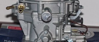
Carburetor Features
The main difference between this fuel system and an injector is the presence of a special mixture former. Its name is carburetor. It is in it that the fuel-air mixture is prepared. The carburetor is installed on the intake manifold. Fuel is supplied to it, which is subsequently sprayed using jets and mixed with air. The finished mixture is supplied to the manifold through the throttle valve. The position of the latter depends on the engine load level and its speed. By the way, the diagram of the fuel system of a gasoline engine is shown in the photo below:
As you can see, during the preparation and combustion of the fuel mixture, a lot of electronic sensors are involved. Of particular importance for the car is the throttle position and crankshaft speed sensor.
We also note that the carburetor-type fuel system design (UAZ “Bukhanki” included) is characterized by a low level of pressure that is formed when fuel is pumped. The very supply of gasoline to the engine cylinders is carried out by gravity, that is, when the pressure in the combustion chamber decreases when the piston reaches BDC.
Combined fuel supply
As you probably already guessed, this is an attempt to combine two systems at once, namely: distributed and direct injection.
One cylinder has two injectors (injectors) at once - one is located in the intake manifold, the other is located directly in the cylinder, that is, it is a kind of combining two systems and taking advantage of the advantages of both.
However, as a rule, they do not simultaneously pump fuel, but distribute the load according to operating modes:
- So at low speeds with minimal load, say, for example in the city, in traffic jams, distributed injection works
- At high speeds and high speeds and loads, direct injection is switched on, it “slightly” increases power (about 5%), saves fuel and reduces emissions into the environment.
The positive aspects of the combined system are the combination of the advantages of various designs, the greatest efficiency and environmental emissions are achieved.
Negative points - an even more complex design (often two fuel rails and two pumps), complex repairs - diagnostics, high prices. That is why such systems are used almost only on business class cars.
Injector features
The fuel system diagram (including Mercedes E200) of the injection type has a fundamental difference from the carburetor analogue:
- Firstly, fuel from the tank in it is supplied to a ramp to which spray nozzles are connected.
- Secondly, air is supplied to the engine combustion chamber through a special throttle assembly.
- Thirdly, the level of pressure created by the pump in the system is many times greater than that created by the carburetor mechanism. This phenomenon is explained by the need to ensure rapid injection of fuel by the nozzle into the combustion chamber.
But this is not the only difference between a fuel injection system and a carburetor. The Chevrolet Niva (its fuel diagram is shown in the photo below), like other modern cars, has at its disposal so-called “electronic brains,” that is, an ECU. The latter is responsible for collecting and processing information from all existing sensors in the car.
So, the ECU also controls gasoline injection. Depending on the operating mode, the electronics independently determine which mixture needs to be fed into the cylinder - lean or rich. But this is not the only difference between the injection-type fuel system (Ford Transit CDi among others). It can have a different number of nozzles. We will talk about this in the next section.
Fuel injection scheme for injection cars
Currently, there are two types of injection systems:
- Single injection.
- With distributed injection.
In the first case, fuel is supplied to all cylinders using one nozzle. At the moment, single injection systems are almost never used on modern cars, which cannot be said about cars with distributed injection. The peculiarity of such injectors is that each cylinder has its own individual nozzle. This installation scheme is very reliable, and therefore all modern automakers use it.
Difference between gasoline and diesel engines
Before you pay close attention to the design and operating principle of different types of fuel systems, you need to clearly understand how a gasoline engine differs from a diesel unit. and the differences, by the way, are quite significant. First of all, it is worth noting the compression ratios that are necessary for ignition of different types of fuel:
- For gasoline it is 9-11 atmospheres;
- For diesel fuel – as much as 19-25 units.
The design of gasoline and diesel engines does not have any special differences, since in the other, compression occurs with an explosion of the fuel mixture. The only thing worth noting is the stronger alloys used to create diesel units. It is clear that the compression ratio is higher, the loads are greater, and non-reinforced components simply would not be able to compete with gasoline engines in terms of service life. As a result, the weight and overall size of a diesel engine is noticeably larger than a gasoline engine.
However, the main difference lies far from this. The basis of this issue lies in the methods of forming the fuel mixture that ignites in the cylinders. The fact is that in the cavity of gasoline engines, fuel enters immediately in a mixture of gasoline and air. In diesel, air and fuel are sent separately. The principle of its operation is as follows:
- First, air enters the cavity of each cylinder, which is literally compressed in an instant and heated to 700-800 degrees Celsius;
- After this, already at the final stage of compression, the injectors deliver the required amount of fuel to each cylinder;
- In the end, an inevitable explosion of the fuel mixture occurs, which pushes the motor shafts that ensure the movement of the car.
For those who are not well acquainted with physics, it will be surprising that such an engine organization does not require the use of spark plugs. The start of a diesel engine occurs with the help of heating elements, which, at the stage of starting the internal combustion engine, heat the air in the cylinders to the desired temperature. Then, when several compression strokes and explosions have occurred, the heating elements are not needed at all, since the temperature in the cylinders does not drop, and they turn off. As a result, the air naturally heats up itself and is already “personally” capable of igniting the resulting fuel.
It is this difference between gasoline and diesel engines that provoked the difference in the design of their fuel systems. Previously, in terms of ease of use and due to the insignificant difference in efficiency, gasoline units outperformed diesel engines. The latter worked noisily and with strong vibration. However, the development of the automotive industry was veiled by these shortcomings and the two types of engines became real competitors.
How does the injector work?
The operating principle of this system is very simple. Fuel from the tank is supplied to the ramp under the action of a pump (the fuel in it is always under high pressure). Next it goes to the nozzles, through which it is sprayed into the combustion chamber. It is worth noting that injection does not occur constantly, but at certain intervals. Simultaneously with the supply of fuel, air enters the system. After the mixture of fuel has occurred in a certain proportion, it enters the combustion chamber. The process of preparing the mixture with injectors is several times faster than with carburetor systems. We also note that the operation of the spray nozzles is controlled by a number of additional sensors. Only by their signal does the electronic unit give the command for fuel injection. As you can see, the layout of an injection-type fuel system differs from a carburetor one. First of all, it has separate nozzles that inject fuel into the combustion chamber. Well, then, as in carburetor cars, the spark plug excites a spark and the fuel combustion cycle takes place, which then turns into the power stroke of the piston.
Additives and their use
In conclusion, I would like to talk a little about additives for flushing injectors, in which systems should they be used and in which should they not be used?
Firstly , the use of any additives for cleaning injectors, whether distributed or direct injection, must be done at your own peril and risk. There are a lot of fakes, a lot of deception, and you can “crash” the injector even worse than cleaning it.
Secondly , distributed injection is less susceptible to an aggressive environment, because it is located in the intake manifold, there are no high temperatures, and therefore such injectors can run for 70 - 80,000 without cleaning. You can add fuel additives to them, which (if they work) can easily “wash away” the deposits on them. THIS IS REASONED HERE!
Thirdly , direct injection, as I already wrote - that the injectors are in an aggressive environment! All sorts of deposits are simply baked on them (which settles both in the cylinders and on the spark plugs). It is difficult to wash it off, and with the use of some additives - so it is advisable to remove them and clean them at a service station, on a stand, and let them demonstrate their performance to you. YES it is more expensive, but I told you that such a fuel supply system is more expensive to operate. I WOULD NOT USE ADDITIVES TO CLEAN THEM.
That’s it, now there’s a detailed video version of the article, for those who didn’t understand, I tried to make it simple.
Read our AUTOBLOG, there will be many more useful articles and videos.
Similar news
- Engine without valve springs. Really a revolution in the engine industry...
- Efficiency of an internal combustion engine. Approximately how much is...
- Scratches on the car body
Add a comment Cancel reply
Diesel fuel system diagram
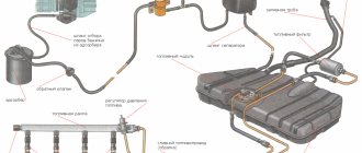
The fuel supply system of a diesel engine has its own characteristics. Firstly, fuel is supplied to the combustion chamber by a nozzle under enormous pressure. Actually, due to this, the mixture in the cylinders ignites. On injection engines, the mixture ignites using a spark created by a spark plug. Secondly, the pressure inside the system forms the injection pump (high pressure fuel pump).
That is, the layout of the fuel system (including MAZs and KamAZs) is such that two pumps are used for injection. One of them is low pressure, the second is high. The first (also called pumper) supplies fuel from the tank, and the second directly supplies fuel to the injectors.
Below is a diagram of the fuel system (KAMAZ 5320):
As you can see, many more elements are used here than on carburetor cars. By the way, on some modifications of KamAZ engines an additional turbocharger is installed. The latter performs the function of reducing the level of toxicity of exhaust gases and at the same time increases the total power of the internal combustion engine. This design of the fuel system (KAMAZ 5320-5410) allows fuel to be pumped under higher pressure. At the same time, the total fuel consumption remains at the same level.
Device evolution
The number of cars is growing every year, emissions into the atmosphere are becoming more and more. Therefore, engineers of large concerns are fighting for the ecology of emissions, systems such as EURO are being adopted, now in Russia they have already reached “EURO 5”, in Europe this is already “EURO 6”, and “EURO 7” should appear soon. Each increasing level imposes strict requirements on many components, and in particular on the fuel supply system; if such requirements did not exist, it is quite possible that we would still be riding on “carburetors”, or let’s say on “mono-injection”. In the design of our cars, there would be no such parts as a catalyst. But ecology is ecology, and in general I support manufacturers; to be honest, I’m generally in favor of electric cars or, for now, hybrids. Still, living on a dirty planet is not entirely good! Well, okay, this is a lyrical digression - but now to the point.
If you track the evolution of fuel supply systems, and today I’m talking specifically about gasoline options (we’ll talk about diesel later). Then we can define only five main structures, in increasing order. SO:
- Carburetor
- Mono injection (or central)
- Distributed injection
- Direct injection
- Combined system
As you understand, the very first was the carburetor (very environmentally friendly, EURO1 standard), now the most progressive type is direct injection (the most environmentally friendly at the moment, EURO5 - EURO6). Let's take a closer look at each design; many are probably waiting.
Work algorithm
The operating principle of diesel systems has many complexities, unlike the injector. The layout of the fuel system (Ford Transit TDI) is such that the fuel, using a booster pump, passes through a fine filter and is supplied to the injection pump. There it enters the injectors located in the cylinder head under high pressure. At the right moment, the mechanism opens, and after this the combustible mixture is sprayed into the chamber, into which pre-purified air is supplied through a separate valve. The excess diesel fuel from the high-pressure pump and nozzles returns back to the tank (but not through the filter, but through separate channels - ebb pipes). Thus, the fuel system circuit of a diesel engine is more complex and requires higher precision when preparing the combustible mixture. Accordingly, the cost of servicing such engines is higher than repairing injection engines.
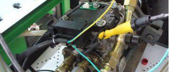
Coarse and fine fuel filters
Fuel is purified from mechanical impurities and water in coarse 9 and fine 3 filters. The coarse filter, installed in front of the main fuel pump 8, traps particles measuring 20...50 microns, which account for 80...90% of the mass of all impurities. A fine filter, placed between the main fuel pump and the injection pump, traps impurities with sizes of 2...20 microns.
Currently, the following types of coarse filters are used in diesel power plants:
- mesh
- tape-slit
- plate-slit
For mesh filters, the filter element is a metal mesh. It can be used to form concentric cylinders through the walls of which fuel is pressed, or disk-shaped sections strung on a central pipe with holes in the wall connected to the outlet pipeline.
In a slotted belt filter, the filter element is a corrugated glass with a profile tape wound on it. Through the gaps between the turns of the tape formed by its protrusions, fuel from the space surrounding the filter element enters the depressions between the corrugated glass and the tape, and then into the cavity between the bottom and the lid of the glass, from where it is removed through the outlet pipeline.
The filter element of a plate-slit filter is a hollow cylinder made up of identical thin annular disks with folded projections. Due to these protrusions, gaps are formed between the disks. The fuel flows to the outer and inner surfaces of the cylinder and, passing through the slots between the disks, is cleaned. The cleaned fuel is directed through the end holes in the disks to the upper part of the filter to the outlet.
Very often, a coarse filter is combined with a settling tank for water contained in diesel fuel. In this case, it is necessary to periodically unscrew the sump plug to remove accumulated water from it.
In fine filters, cardboard elements of the “multi-beam star” type or bags of cardboard and felt disks are usually used as filter elements. Less commonly used are frames with padding that absorbs mechanical impurities (for example, mineral wool), frames with fabric or thread winding, etc.
During vehicle operation, fuel filters become dirty, which leads to an increase in their resistance. To ensure that the fuel supply to the injection pump does not stop, it is necessary to periodically wash the coarse filter and replace the fine filter element with a new one.