Sooner or later, any car enthusiast may be faced with the need to remove the intake manifold on a 16-valve VAZ-2112 engine. This may be needed to carry out incidental repair operations or other work.
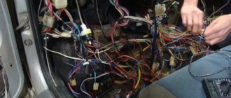
The video will tell you how to remove the intake manifold, and also tell you about all the subtleties and nuances
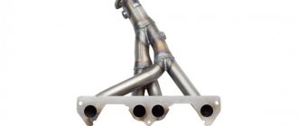
Intake manifold removal process
General view of the intake manifold
Dismantling the intake manifold is carried out with the car cooled down for safety reasons. So, this operation can take about an hour and will require some knowledge of the car’s design, namely the injection system. So, let's consider the sequence of actions for dismantling the unit:
- We dismantle the throttle. To do this, it is not necessary to disconnect all the pipes and pipes; it is enough to disconnect the unit from the manifold and move it to the side. Of course, at the same time, it is still recommended to remove the throttle valve completely for cleaning.
Location of the throttle valve on a VAZ-2112 - photo of an editorial car
Removed the wires and coil
Unscrew the clamp and disconnect the vacuum brake booster tube
Using a Phillips screwdriver, unscrew the oil level indicator guide tube
Unscrew the ignition coils and receiver
Unscrew the bolts securing the manifold to the block head
Pull the collector towards you and dismantle it
It is worth noting that installation of the intake manifold is carried out in the reverse order and does not require any additions or changes.
Video
Main signs of pollution
While driving a car, various gases, traces of oil and dust particles enter the outer and inner walls of the throttle valve, which the air filter is not able to retain. This can cause deposits on the walls of the damper and lead to disruption of the normal functioning of this element of the intake system.
Typical signs of a clogged throttle body are:
- Difficulties in engine operation at idle, when it stalls or the speed fluctuates.
- Unstable starting of the internal combustion engine when it starts with difficulty.
- The appearance of car jerking at a speed of less than 20 km/h when pressing the accelerator pedal.
- Noticeable increase in fuel consumption.
The main causes of damper contamination include:
- Poor quality gasoline. This factor is considered the most common cause of contamination that requires cleaning the throttle valve. The reason for the low quality of fuel may be various impurities and additives added to increase the octane number of gasoline and ultimately precipitate. These contaminants enter the throttle and turn into carbon deposits, which interfere with the operation of the unit.
- Microparticles of motor oil that enter the assembly structure through the ventilation system, as well as dust particles that penetrate from the atmosphere into the air duct. These elements mix with each other and interfere with the normal movement of the valve, and ultimately disrupt the operation of the engine as a whole.
- A clogged fuel filter causes throttle contamination due to untimely replacement of this element. Once dirt elements from the filter element get onto the damper, it can no longer move as intended during the production of the car. Accordingly, when the damper is opened slightly, a small amount of air enters, which is why the fuel does not even ignite.
- Excessive air dust also often causes throttle contamination. Dust can enter the damper through a damaged air filter or faulty air duct, thereby interfering with its normal operation.
conclusions
Dismantling the intake manifold of a 16-valve VAZ-2112 is quite easy and simple. Of course, it’s worth understanding at least a little about the design of the main power unit, but if desired, any car enthusiast can remove this unit.
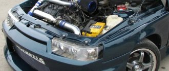
The 16-valve VAZ-2112 engine was at one time the most dynamic and responsive engine in the VAZ lineup, which made it both the most popular and difficult to repair and maintain. In this article we will tell you in detail about the design of this engine, its advantages and disadvantages.
Causes of malfunctions
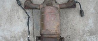
The gasket is placed between the exhaust manifold and the cylinder head. The stamped asbestos gasket is resistant to high temperatures, can be compressed (creating the necessary impermeability) and has increased strength. To enhance the latter quality, the exhaust manifold gaskets are additionally reinforced with steel.
IMPORTANT! The main task of the gasket is to prevent exhaust gases from penetrating under the hood, where they can cause ignition of parts/assemblies of the engine compartment. The gasket is recognized as the most vulnerable point of the exhaust manifold, which operates under extreme loads in both temperature and pressure
It is not surprising that gaskets have to be changed not only on cars with a significant mileage, but also on almost new cars
The gasket is recognized as the most vulnerable point of the exhaust manifold, which operates under extreme loads in both temperature and pressure. It is not surprising that gaskets have to be changed not only on cars with significant mileage, but also on almost new cars.
Gaskets need to be rotated for several reasons:
- poor factory quality;
- engine overheating due to intensive use;
- engine repair (a used gasket loses its properties when dismantled).
Schematic sketch of the VAZ-2112 engine
Detailed diagram of the VAZ-2112 engine.
1 – engine sump. 2 – front crankshaft oil seal. 3 – crankshaft. 4 – crankshaft pulley. 5 – oil pump. 6 – generator drive pulley. 7 – timing belt. 8 – front cover of the timing mechanism drive. 9 – coolant pump pulley (pump). 10 – tension roller. 11 – camshaft toothed pulley. 12 – rear cover of the timing mechanism drive. 13 – camshaft oil seal. 14 – exhaust camshaft. 15 – hydraulic pusher. 16 – valve spring. 17 – valve guide sleeve. 18 – exhaust valve. 19 – receiver. 20 – camshaft bearing cover. 21 – guide pipe. 22 – cylinder head cover. 23 – plastic cover. 24 – spark plug. 25 – intake camshaft. 26 – inlet valve. 27 – cylinder head. 28 – coupling. 29 – fuel rail. 30 – crankcase ventilation hose. 31 – nozzle. 32 – intake manifold. 33 – flywheel. 34 – crankshaft rear oil seal holder. 35 – rear crankshaft oil seal. 36 – cylinder block. 37 – oil dipstick. 38 – piston. 39 – connecting rod. 40 – connecting rod cover. 41 – crankshaft main bearing cover.
Comments
Repair manuals
Mikha
wrote on 07/26/2015 Guys! I’ll tell you right away that it’s better not to get involved in such a responsible task. My son-in-law said yesterday that it’s like two fingers on… asphalt. In short, we argued, it’s a pity that it was for a bottle of beer, but that’s not the point. So he ruined the whole life and that’s all. Of course, I won, but I had to help my son-in-law. In general, I unscrewed all the sensors and tubes, removed the power steering reservoir, and drained the fluid from it. I took out the intake manifold. By twisting the membrane (vacuum) to pull out the quadratic axis. I looked, everything seemed to be fine on the damper, and then mine said that it was the only one knocking and pointed to the end. I pulled out the axle with a hammer and nail, since the dampers were firmly on the axle. The son-in-law began to dig out the valves; one of his doors cracked, but the rest remained intact. Having freed the manifold from the flaps, I started cleaning it, but I didn’t find anything except 95, but what to do... I started cleaning the oil separator. Afterwards, he stacked it a little, inserted new bushings and flaps. And he began the reverse process, which is no less labor-intensive! There’s nothing complicated here, you just need to do it without pressure so that nothing cracks)
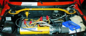
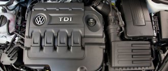
Engine device
16-valve 124 engine under the hood of a “two-wheeler”
- The engine is a sixteen-valve, in-line, four-stroke gasoline engine, consisting of four cylinders. The operating order of the cylinders is: 1-3-4-2 – starting from the crankshaft pulley. With a power supply system – distributed injection, controlled via a Bosch, “January” or GM controller.
- The engine is secured in the engine compartment using four elastic supports, of which the front and rear are rods that are fixed from the engine to the body, and the left and right are identical to the VAZ-2110(11).
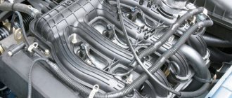
- On the engine, on one side there are camshaft and crankshaft drives, a coolant pump (about checking the pump and choosing a pump - note), a generator, as well as a timing belt (about replacing it here), on the other side there are sensors: coolant temperature, pressure oil, starter, thermostat, front: ramp with injectors, intake manifold, oil dipstick, knock sensor, crankcase ventilation hose, phase sensor. On the reverse side: oil filter, crankshaft position sensor, exhaust manifold. Top: spark plugs, high-voltage wires. More details about all sensors are written here.
- The cast-iron cylinder block has the same index “21083” with engines from the VAZ-2110 (11), however, they have different screws for the cylinder heads M10x1.25 in contrast to M12x1.25, as well as their smallest entry depth.
- Each engine has its own serial number.
Cylinders
This is what the cylinder block looks like with the engine removed.
The engine cylinders are bored directly into the block. The initial diameter is 82 mm and during repairs can be increased by 0.4 or 0.8 mm. The class of the cylinder is marked on the bottom plane of the block in Latin letters.
Crankshaft
This element practically does not fail.
The crankshaft is made of high-strength cast iron, and is equipped with five main journals, four connecting rod journals, and eight counterweights cast together with the shaft. The difference between this crankshaft and its analogues with the VAZ-2112 is due to its increased strength and wear resistance, so installation from younger models is completely excluded. The flywheel is secured to the back of the crankshaft using six self-locking bolts.
When to change: self-diagnosis
The fuel system of an injection engine has a fairly extensive architecture and faults can only be identified after an accurate diagnosis of each of the system elements. For example, a drop in engine power may be the result of either a malfunction of the injectors, insufficient performance of the fuel pump or a clogged fuel filter.
In addition, jerks and dips, unstable idle and difficult starting, increased consumption, can occur when the injector is simply clogged.
You can check the injectors themselves directly on the engine without removing them. To do this, just start the engine and remove the wires from the connector one by one. If the stability of the engine changes at the same time, the engine starts to oscillate, then the injector is in order. If, when removing the wires from the connector, the stability of the motor does not change, the injector needs to be cleaned or replaced.
Sources
- https://rmo-ru.ru/dvigatel/vpusknoj-kollektor-na-vaz-2112.html
- https://ilifia-club.ru/dvigatel/kak-snyat-vpusknoj-kollektor.html
- https://avto-mekhanik.ru/dvigatel-i-navesnoe/kak-snyat-vpusknoj-kollektor-na-vaz-2112-16-klapanov-plastikovyj.html
[collapse]
Modifications of the VAZ-2112 car
VAZ-21120 . Modification with a 16-valve injection engine with a volume of 1.5 liters and a power of 93 horsepower. 14-inch wheels were installed on the car. This modification has a problem with valves bending when the timing belt breaks. The problem can be solved by increasing the depth of the grooves in the piston bottoms.
VAZ-21121 . The car was equipped with a VAZ-21114 8-valve injection engine with a volume of 1.6 liters and a power of 81 horsepower.
VAZ-21122 . Budget modification with an 8-valve injection engine VAZ-2111. The car was produced without electric windows, the wheels were 13 inches in size, and the brakes were unventilated from a VAZ-2108 car.
VAZ-21123 Coupe . Three-door, five-seater hatchback. The only two doors for entering the car are 200 millimeters wider than those of the five-door hatchback, and they are mounted on new, durable hinges. The rear arches of the car have become wider. The engine was installed with a 16-valve injection engine with a volume of 1.6 liters and a power of 90 horsepower. The car was produced from 2002 to 2006 in small quantities, the reason for this was the high cost of the car.
VAZ-21124 . Modification with a 16-valve injection engine VAZ-21124 with a volume of 1.6 liters. Produced from 2004 to 2008. For this type of engine, the problem with valve bending was solved. To do this, the depth of the grooves in the piston heads was increased (up to 6.5 mm). In addition, the design of the cylinder block was changed to achieve a working volume of 1.6 liters, for which its height was increased by 2.3 mm, and the radius of the crankshaft was increased by 2.3 mm accordingly. There were also a number of other minor changes.
VAZ-21128 . The luxury version of the car, produced by Super-auto JSC, was equipped with a 16-valve VAZ-21128 engine with a volume of 1.8 liters and a power of 105 horsepower.
VAZ-2112-37 . A racing modification of the VAZ-2112, prepared for the “ring” in the Lada Cup qualifying group. The car was equipped with a 1.5-liter VAZ-2112 engine with a power of 100 horsepower. The racing car was equipped with a safety cage, an external aerodynamic kit and a front extension of the strut support cups.
VAZ-2112-90 Tarzan . All-wheel drive modification with a VAZ-2112 body on a frame chassis with transmission and suspension parts from a VAZ-21213 Niva. It was also equipped with a 1.7 or 1.8 liter engine from the Niva.
Tuning
Simple firmware or chip tuning for 124 engines not the technical characteristics . To significantly increase power, it is necessary to modify the engine.
- The simplest and most common tuning of the 21124 engine is the installation of sports camshafts, a direct-flow resonator, an increased throttle - in this way you can increase the power to 120 hp. Installing a lighter piston engine can add some power to this. This, at the same time, will reduce the fuel consumption of the VAZ 21124.
- About 150 hp can be ensured by modification of the cylinder head and installation of camshafts with increased valve opening phases.
- Installing a compressor has approximately the same effect; it is installed on eight-valve and sixteen-valve engines.
- Stable engine operation at any speed is ensured by installing four chokes, one for each cylinder. According to popular experience, the most suitable option is to install an injection system from ToyotaLevin. To do this, a set is assembled from the chokes themselves, an adapter manifold, a zero-resistance filter, injectors, an absolute pressure sensor and a fuel pressure regulator. Due to the fact that the speed exceeds the limit, it is necessary to install lightweight piston and wide-phase camshafts. With this modification, engine power can reach 200 hp. But such modernization sharply reduces the service life of the engine, is fraught with frequent breakdowns and the need to carry out serious repairs of the VAZ 124, due to the fact that the engine easily and often spins up to 9,000 rpm.
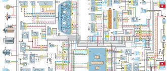
Electrical diagram of VAZ-2112
Designations: 1 – Headlight, 2 – Klaxon, 3 – Main radiator fan, 4 – Starter, 5 – Battery, 6 – Generator 2112, 7 – Gearbox limit switch (reverse), 8 – Actuator in the front passenger door, 9 – Power window enable relay, 10 – Starter relay, 11 – Heater fan, 12 – Electric heater partition drive, 13 – Main pump, 14 – Washer reservoir sensor, 15 – Driver’s door actuator, 16 – Front passenger window selector, 17 – Unlock button fifth door, 18 – Heater fan resistance unit, 19 – Main wiper motor, 20 – Driver’s window lift selector, 21 – Front passenger’s window lift motor, 22 – Central locking, 23 – Exterior light switch, 24 – Brake fluid leakage sensor, 25 – Pump additional, 26 – Driver's window lift motor, 27 – PTF on indicator, 28 – PTF switch, 29 – Dashboard, 30 – Heated glass on indicator, 31 – Heated glass switch, 32 – Steering column selector switch, 33 – PTF relay, 34 – Ignition switch, 35 – Main fuse block, 36 – Illumination of heater controls, 37 – Hazard warning button, 38 – Heater control controller, 39 – Glove compartment lighting, 40 – Glove compartment lid end cap, 41 – Cigarette lighter, 42 – BSK – display unit, 43 – Ashtray illumination, 44 – 12V socket, 45 – Instrument lighting switch, 46 – Actuator in the right rear door, 47 – Right rear passenger window selector, 48 – Clock, 49 – Right rear passenger window motor, 50 – Brake limit switch (closed – pedal is pressed), 51 – Left rear passenger window motor, 52 – Left rear passenger window selector, 53 – Actuator in the left rear door, 54 – Turn signal, 55 – Handbrake limit switch (closed – handbrake on), 56 – Rear wiper motor , 57 – Navigator's lamp, 58 – Interior lamp, 59 – Temperature sensor in the heater, 60 – Limit switch for the open front door, 61 – Limit switch for the open rear door, 62 – Trunk light, 63 – Rear optics (on the body), 64 – Rear optics (on the fifth door), 65 – License plate illumination.
The letters indicate the terminals to which it is connected: A – Front speaker on the right, B – Radio, C – Injector harness, D – ESD diagnostic connector, D – Front left speaker, E – Diagnostic connector for the heater controller, G – Rear right speaker, W – Rear left speaker, I – BC connector, K – glass heater thread, L – fifth door actuator, M – Additional brake light.
Wiring diagram VAZ-2112 injector 16 valves - full view
My LADA 2110 “Red Swallow”
Many people have their own cars, of various brands, configurations, tuned and simply “gray” cars for everyday driving. Some make various gadgets for cars with their own hands, some send them to special services, and others simply admire how people do it. Actually, this is what I would like to talk about - tuning!
I didn’t have a car before and somehow didn’t need one, but in my heart I always wanted to sit, steer and enjoy the speed. The first step to buying a car was getting a driver's license, which I also went to study for spontaneously. In general, I studied for 3 months in DOSAAF and 29.
On 02.2008 I received my driver's license. From time to time there was a desire to buy a car, but there was no money to buy it, and I began to think about it – where should I go?
Time passed, years flew by, rumors circulated about a crisis. By that time, we had managed to save a little cash, which we finally decided to invest in some kind of automobile before it disappeared.
One wonderful morning, we got ready and went to the car market in Saratov to choose a car for me.
I had to borrow a considerable additional amount of cash from friends, otherwise my savings were not enough.
We set off on the road, drove and drove, and finally arrived. Let's go to the market.
There were a lot of cars in Saratov, some not for our money, others too dead, in general, we wandered and wandered and saw a red VAZ2110 (my favorite color). After some time, after a lot of walking, it was finally decided to buy the first car I liked and finally go home.
The path to home was not close, about 200 km. At first, I thought that my friend would drive and drive my car to my native Kamyshin, but I still drove it back myself.
This is my very first time when I drove for so long, because the last time I held it in my hands was back in February and that was for about 10 minutes. For the first 10-20 minutes I couldn’t come to my senses that I was sitting behind my own car, My hands were shaking a little and I still couldn’t believe that I was going.
Literally, after driving 50 kilometers, I already began to feel much more confident, fell back on the seat and began to enjoy the trip.
Everything would be fine, but in Krasnoarmeysk at the traffic police checkpoint we were stopped to check our documents. And I stupidly took only my license with me, and the rest of the documents remained with my mother, who drove ahead in another car with a driver. Luckily they stopped about 300 meters from us.
The inspector had to wait for some time, to which he made a menacing expression on his face. They brought the documents, checked everything, but still got to the bottom of the fact that there was no first aid kit, fire extinguisher and sign.
We got home quickly, we drove for about 3 hours in total, although it could have been longer, but I was still a beginner at that time, and the car was not tested, you never know what would break down, so I kept the speed around 100-110 km/h . But still, there was a desire to experience the drive and therefore I accelerated once to 155 km/h, the car behaved amazingly on the road, I remained satisfied throughout the entire journey.
Here is a short story about the steps to buying my first car, which is with me to this day and makes me happy. From time to time I do something for the soul in it, a little tuning, etc. what I will tell you about in my Logbook
.
Express your opinions about my work, and just like that, we can discuss something, further work, plans...
VAZ-21124 engine control circuit
Connection diagram of the VAZ-21124 engine control system with distributed fuel injection to Euro-2 emission standards (controller M7.9.7): 1 - ignition coils; 2 — nozzles; 3 - controller; 4 - main relay; 5 - fuse connected to the main relay; 6 — cooling system electric fan relay; 7 - fuse connected to the cooling system electric fan relay; 8 - electric fuel pump relay; 9 - fuse connected to the electric fuel pump relay; 10 — mass flow and air temperature sensor; 11 — throttle position sensor; 12 — coolant temperature sensor; 13 — solenoid valve for purge of the adsorber; 14 — oxygen sensor; 15 — knock sensor; 16 — crankshaft position sensor; 17 — idle speed regulator; 18 — immobilizer control unit; 19 — immobilizer status indicator; 20 - phase sensor; 21 — vehicle speed sensor; 22 — electric fuel pump module with fuel level sensor; 23 — oil pressure warning lamp sensor; 24 — coolant temperature indicator sensor; A - block connected to the wiring harness of the ABS cabin group; B — diagnostic block; B - block connected to the air conditioner wiring harness; G - to the “+” terminal of the battery; D — to the side door wiring harness block; E - block connected to the instrument panel wiring harness; G1, G2 - grounding points; I - the order of conditional numbering of plugs in the block of the immobilizer control unit; II - the order of conditional numbering of contacts in the diagnostic block.
Connection diagram of the VAZ-21124 engine control system with distributed fuel injection under Euro-3 toxicity standards (controller M7.9.7): 1 - ignition coils; 2 — nozzles; 3 - controller; 4 - main relay; 5 - fuse connected to the main relay; 6 — cooling system electric fan relay; 7 - fuse connected to the cooling system electric fan relay; 8 - electric fuel pump relay; 9 - fuse connected to the electric fuel pump relay; 10 — mass flow and air temperature sensor; 11 — rough road sensor; 12 — throttle position sensor; 13 — coolant temperature sensor; 14 — idle speed regulator; 15 — control oxygen sensor; 16 — diagnostic oxygen sensor; 17 — solenoid valve for purge of the adsorber; 18 — knock sensor; 19 — crankshaft position sensor; 20 — immobilizer control unit; 21 — immobilizer status indicator; 22 - phase sensor; 23 — vehicle speed sensor; 24 — electric fuel pump module with fuel level sensor; 25 — oil pressure warning lamp sensor; 26 — coolant temperature indicator sensor; A - block connected to the wiring harness of the ABS cabin group; B — diagnostic block; B - block connected to the air conditioner wiring harness; G - to the “+” terminal of the battery; D — to the side door wiring harness block; E - block connected to the instrument panel wiring harness; G1, G2 - grounding points; I - the order of conditional numbering of plugs in the block of the immobilizer control unit; II - the order of conditional numbering of contacts in the diagnostic block.
Reasons for the appearance of oil in the air filter and its housing
Air filter that has absorbed oil
If we take the normal condition of the car, then the air filter must be dry throughout its entire service life. But the presence of oil indicates that there are problems in the mechanical part of the engine. Therefore, we will not consider problems in the electronic control unit, since this part has nothing to do with it in this case . So, let's look at the reasons for this effect:
- Compression.
- Adjustment of valves.
- Crankcase ventilation.
- Additives.
- Catalyst.
Once the causes have been considered, you can move directly to methods for solving problems, in the order in which they might occur.
Solution methods
The main reason where the problems lie is the valve stem seals. It is through them that the oil enters the pipe, which squeezes the lubricant onto the filter. First of all, it is necessary to replace this particular element. Of course, there are quite a lot of reasons besides valve seals, so it is necessary to dwell on each separately.
Air filter in oil compared to new and clean
Compression drop
A loss of compression may cause traces of oil to be visible on the air filter element. The problem can be corrected quite easily - a small tube with a diameter of 1 mm extends from the brood pipe near the crankcase. It often gets clogged, which causes a drop in compression. Next you need to clean it and put it in place. If you put your finger to the tube and feel that it is being sucked in, then you need to adjust the valves.
The process of measuring engine compression
Adjustment of valves
A fairly common cause, along with valve stem seals, is incorrect valve clearance. A characteristic sign is the appearance of bluish smoke from the exhaust system. To eliminate the malfunction, a simple adjustment of the valve clearances is necessary. This is quite simple and not difficult to do.
Valve clearance adjustment process
Crankcase ventilation
One of the reasons for the appearance of oil in the car air filter is the oil level is higher than normal or its poor quality . So, at an increased level, the crankshaft creates foam, which enters the rest of the system through the ventilation pipes, especially the air filter element.
VAZ-2112 harness diagrams
Instrument panel harness diagram
1, 2, 3, 4 – instrument panel harness pads to the front harness; 5 — block of the instrument panel harness to the side door harness; 6, 7, 8 — instrument panel harness pads to the rear harness; 9 – rear window heating switch; 10 – light signaling switch; 11 – windshield wiper switch; 12 – block of the instrument panel harness to the radio; 13 – mounting block; 14 — instrument cluster; 15 – heater control controller; 16 – heater motor switch; 17 — block of the instrument panel harness to the ignition system harness; 18, 19 — blocks of the instrument panel harness to the air supply box harness; 20 — ignition switch; 21 – fog lamp relay; 22 – sound signal relay; 23 — power window relay; 24 — starter relay; 25 – seat heating relay; 26 – external lighting switch; 27 – fog lamp switch; 28 – cigarette lighter; 29 – lampshade lighting of the glove box; 30 – glove box lighting switch; 31 – switch for rear fog lights; 32 – right steering column switch; 33 – socket for connecting a portable lamp; 34 — instrument lighting switch; 35 – brake signal switch; 36 – sound signal switch; 37 – alarm switch; 38 – air distribution drive gearmotor; 39 – VAZ-2112 illuminator; 40 — instrument panel harness block to the front harness; 41 – trunk lock drive switch; 42 – rear fog light relay.
A – grounding point of the instrument panel harness.
Ramp
The ramp is removed as an assembly with the fuel pressure regulator:
- It is necessary to disconnect the vacuum hose from the regulator.
- Using 2 open-end wrenches 17, unscrew the fittings securing the gasoline supply pipes to reduce pressure.
- Disconnect the ramp voltage connector.
- Using a screwdriver, unscrew the screw of the bracket for fastening the gasoline supply and outlet pipes and disconnect it.
- Using a hexagon, unscrew the 2 screws for fastening the ramp.
- Pull the ramp in the axial direction of the injector from the seat, remove the ramp towards the left side of the hood.
Note: follow the direction of travel of the vehicle.
- Unscrew the nut from the left intake manifold bracket and loosen the lower bolt.
- Remove the bracket from it.
- Perform the same operation with the right bracket and remove it.
- Unscrew the 2 nuts from the eye stud.
Removing the eye
- Unscrew the 3 nuts from the receiver bracket and remove it.
- Carefully remove the bushing from the intake manifold stud.
- Disconnect the exhaust air intake pipe and remove it from the lower intake air studs.
- Unscrew the top nut and loosen the bottom nut a little on the bar.
Note. It holds the antifreeze pump tubes for cooling. The bar at the bottom has a through slot; carefully remove it.
The intake manifold is mounted on studs, so you need to unscrew one nut on top and 2 on the side. To remove the exhaust manifold, you need to unscrew an additional 2 nuts. You need to carefully inspect the connection point, since 2 gaskets are installed between the manifold and the block head.
Note
When dismantling the intake manifold, pay attention to the gaskets. If the gasket burns out, antifreeze can get into the cylinder block.
There may be holes drilled by antifreeze on the head of the blocks, and there may also be holes in the gasket.
- Antifreeze may leak into valves and cylinders. In this case, you need to remove it from there using a syringe. Unscrew the spark plugs (see Replacing spark plugs on a VAZ 2110 on your own) and crank them with the starter to remove any antifreeze that gets there. If grooves are found on the surface, the collector must be replaced.
- At the bottom, the exhaust manifold is attached to the exhaust pipe. Then it is connected to the exhaust pipe. Unscrew the three bolts and disconnect the pipe. Remove the collector. You need to unscrew them from the inspection hole and first tap the heads. Use a metal brush to clean the nuts and threads.
- During assembly, replace all gaskets with new ones one by one. It is advisable to tighten the nuts during assembly using a special wrench. Also replace the injector O-rings with new ones.
READ Kia RIO 4 windshield replacement
Gaskets are sold in sets, plus the cost of a set of gaskets and a manifold. When doing your own repairs to replace the exhaust manifold, you must carefully and scrupulously read the instructions. Also view video clips and photos.
Note: photographs must be arranged in order of work. As repair processes are completed, fold them in reverse order. Once you've finished disassembling, turn the stack of photos over. Reassemble in reverse order. Before assembly, the nuts must be lubricated with graphite thread lubricant, and the threads of all bushings must also be lubricated. Thoroughly clean the installation areas of the gaskets from inclusions and foreign contents.
By doing the work yourself, you can save a lot of money, because the price of repairs in special workshops and service stations is very high and not everyone can afford to pay the cost.
View analogues and other offers View analogues
Step by Step Actions
The process of replacing a seal when it fails is simple, but has nuances for different engines. In general terms, the algorithm for dismantling and subsequent installation of the VK gasket looks like this:
- Open the hood and remove the air intake with the carburetor, under which there is a manifold.
- Remove the thermal screen covering the VC (some older models do not have a screen).
- Unscrew the bolts that attach the spider to the exhaust pipe, and then the bolts connecting it to the engine block.
- Proceed to removing the exhaust manifold itself, on which sits a burnt-out gasket, which often “sticks” to the VC.
- Carefully clean the area between the cylinder head and the manifold with a spatula, removing carbon deposits and fragments of worn gasket from the second.
- Once the area is shiny, coat it with graphite lubricant and install a new gasket.
- Treat the fasteners with the same lubricant (to prevent corrosion).
return all dismantled parts to their rightful places.
Comparative characteristics
To help you understand which piston group is better, let’s look at the comparative characteristics of all three manufacturers with photos:
- Let's start with STI products. STI forged pistons are produced in Togliatti using hot stamping. Feedback from consumers who have already installed STI shows that these forged pistons greatly reduce engine efficiency. This is because STI parts have a low compression ratio and a large combustion chamber. It should also be noted that the STI piston alloy contains less silicon, resulting in lower component resistance to high temperatures.
In addition, due to the reduced nickel content in the alloy, the service life of the element can be significantly reduced. At the same time, STI pistons without a cap are more expensive than STK and Avtramat.
Avtramat cast pistons are produced in Kharkov, Ukraine. The pistons are manufactured using an alloy identical to the original Prior parts. However, unlike the latter, Ukrainian-made products can have deep coatings, and this is an undoubted advantage of Avtramat over standard pistons. In this case, we are talking about safety in the event of a timing belt break. As for the compression ratio, in the case of the Avtramat it has not changed.
See also: Cooling fan not working due to above reason
Receivers 16V
This section contains sports intake receivers for VAZ cars, which are equipped with 16-valve engines. The sixteen-valve engine is the most common engine for tuning VAZ cars as it has greater potential for modifications. Accordingly, our online store of tuning spare parts offers you the maximum selection of receivers for 16-valve cars from various manufacturers.
Sports and tuning 16v receivers in this section differ in the production method (welded, cast). Cast aluminum receivers allow you to obtain a more optimal shape for better filling of the cylinders, so they can safely be classified as “sport”. Such receivers include the LADASPORT cast receiver. But the price of such a sports receiver is quite high due to the complex manufacturing technology.
Receivers for tuning VAZ are made of steel, their design and shape also allows you to get good cylinder filling rates (StingerSport channel on YouTube) The price of steel tuning receivers is much lower than the prices of aluminum ones, and besides, steel receivers are made for different types of throttle valves: for throttle VAZ with a maximum bore diameter of 56 mm, and for a GAZ throttle with a bore diameter of 60 mm
How does he work
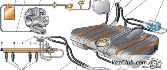
The intake manifold is a complex structure that allows fuel and air to enter the engine.
Upon arrival, they are distributed into streams depending on the number of cylinders in the engine. The moving pistons create a vacuum that reaches its maximum at the lowest point. Therefore, a vacuum is practically formed here, due to which the gases from the crater are neutralized.
The intake system has changed greatly during the development of the automotive industry.
Thus, its structure has come to us in its current form:
- tampon.
- a tube
- muffler,
- intake manifold,
- frame,
- throttle
- pipe outlet,
It turns out that the manifold itself is part of an important system that ensures proper engine operation. Its place is on the left side of the header. Sensors are installed on it to monitor the pressure and temperature inside. The control unit calculates and issues commands.
One of the functions of the intake manifold is to redistribute the air-fuel mixture between the engine cylinders.
The main problem for all car enthusiasts has become overheating of the intake manifold; for this reason, heated air expands and its intake volumes are significantly reduced. Thus, fuel consumption increased and the quality characteristics of the engine decreased. So the technicians decided to make most of the structure out of plastic, which alleviated the problem. However, to avoid breakdowns and other problems, this compartment must be cleaned on time.