01/25/2022 1,419 Alarms
Author: Victor
APS alarms are conventionally divided into two types: early versions with a limited set of options and later ones with expanded functionality. Regardless of the year of manufacture of the anti-theft system, it can be installed on any make of car, both domestic and imported. Configuration and programming of all models of APS security systems is carried out according to one algorithm and allows you to link up to four communicators to the control unit.
[Hide]
Characteristic
Overview of the main characteristics of “APS” alarms for cars:
- to power the car's security system, a 12-volt voltage source is required;
- the rating of safety devices for protecting electrical circuits is 5–15 amperes;
- current consumption level when the protection system is turned on - no more than 20 mA;
- The signaling device is activated after pressing the buttons on the transmitter after 3/45 s;
- the maximum number of alarm mode cycles is 6 pcs. 30 seconds each;
- number of protection zones for car security - 4;
- packet data transmission between the microprocessor and the key fob is carried out at a frequency of 434 MHz;
- operating temperature range for the control unit is from –40 to +85 degrees, for the siren – from –30 to +85°C;
- The degree of protection of the siren according to GOST corresponds to class IP54, for all other elements - IP40.
Optimal operation of the APS microprocessor alarm module is possible at a voltage in the range from 9 to 16 volts. If a load surge occurs in the on-board network that goes beyond these limits, this can lead to damage to the control unit.
Models
There are many models of the APS alarm brand. But the most popular of them are these:
- APS 3900. This model is inexpensive. Has two-way communication. Controls 5 protection zones. Remote control without display. The data transmission channel has a dynamic (constantly changing) security code. There is a security option when the engine is running.
- APS 3800. Main characteristics as the 3900 model. Only 3800 takes control of 6 protection zones. This model is suitable for internal combustion engines with pipe charging.
- APS 3700. Remote control without display. There are an additional 12 options compared to previous models.
- APS 7100. This model is more expensive and is usually bought for business class cars. Has an intelligent protection option. Disabling security in a car is carried out using a two-step algorithm.
- APS 5200. Cheaper than model 7100, but has the Anti-Hi-Jack . The impact controller is two-level. There is a passive immobilizer, which is equipped with a built-in feedback adapter.
- APS 7000. A common model of the APS brand. The system has scanning protection. and interception of the signaling code by a code grabber. There is a two-way connection with the internal combustion engine locking mechanism. Impact control is two-zone.
- APS 7200. Also has protection against theft, scanning and digital signal interception. There is a “ Turbo timer ” mode.
- APS 2300. The remote control has only two buttons and Keeloq coding option. This alarm system includes a siren; you can set different sound tones.
- APS 2500. You can also program different alert sounds in case of an alarm.
- APS 2650. Average cost. There is dynamic code and a two-level shock controller.
- APS 2350. A simple model, very common because it is inexpensive and has all the basic functions.
- APS 1650. The remote control is thin. What else to say. You can also customize the options for yourself.
- APS 1500. This model is expensive, and accordingly, car security has a slightly higher degree of protection.
Equipment
Description of parts and elements included in the delivery set of APS anti-theft systems:
- Main module equipped with a microprocessor. The device includes a board equipped with built-in sensors and relays for blocking electrical circuits of the starter mechanism and controlling door locks.
- Touch controller with the ability to adjust the sensitivity parameter. The device detects physical impacts on the body in two zones - warning and alarm.
- Push-button switch for activating the technical mode of car alarm maintenance.
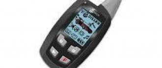
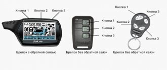
- The main communicator equipped with four keys. The main key fob has a two-way communication function, which is carried out through the display.
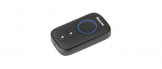
- Spare remote control. The device is not equipped with a screen, so it does not have a warning system.
- LED element for determining the state of the security complex.
- Multi-tone siren.
- Harness with cables for connecting all alarm components.
- Diode elements.
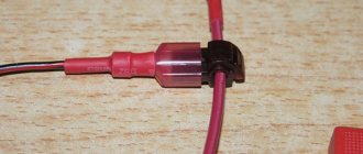
- One limit switch (trigger) for installation on the hood or trunk. The first option is more preferable, since the main components of the vehicle (V) are located in the engine compartment.
- Car windshield stickers.
- Warranty card.
- Service manual for installation and operation. The documentation contains all the nuances that allow you to correctly connect and configure the alarm.
- Packing box.
It is important to know
Since door triggers are not included, these items must be purchased additionally prior to installation.
Video: overview of the APS 3800 system equipment
The “Unpacking Auto Products” channel in its video presented the delivery kit for a car alarm using the example of the 3800 model.
Self-connection of APS 2100
The aps 2100 car alarm connection diagram is included in each kit. With the help of this manual, even a driver who has never done this before can perform the installation.
To successfully carry out installation, you must act in accordance with the instructions. In this case, it is necessary to take into account the following nuances:
- install all elements in places where moisture does not enter
- the central unit, sensors and other parts must be securely mounted on a hard surface, as they are susceptible to constant vibration
- The wiring must be connected into bundles and securely fastened to the body
- It is advisable to install the Valet service button in an inconspicuous place, since attackers know how to disable the aps 2100 car alarm using this key
- Connect wires only in accordance with the diagram, where each wire is connected to the same color.
Advantages and disadvantages
Advantages characteristic of APS car alarms:
- The “signals” of this manufacturer are practically not subject to hacking due to the effective encoding technology of transmitted signals. The pulse format changes every time you press the key fob button, so it is almost impossible to repeat and record a data packet.
- Possibility of using old and new APS security systems on vehicles with carburetor and injection power units.
- Huge functionality comparable to that of full-fledged security systems
- Most popular models are characterized by affordable prices.
- The ability to control window regulators, provided that these devices are equipped with an electric drive.
- A wide range of models with different options and capabilities.
- Easy to connect and install.
Owners of cars with APS alarms highlight the following disadvantages in their reviews:
- low quality of component products, for example, a key fob (due to a weak case, the device can quickly fail);
- spontaneous operation, in particular at low negative temperatures;
- in some service manuals, the colors of the insulating layer of the wires do not match those included in the package, which complicates the connection process;
- low alarm operating range, which in fact can be no more than 50 meters;
- the weak insulating layer of the cables and their thinness lead to the fact that during operation the conductors can crumble, which will lead to short circuits;
- the difficulty of finding spare parts for alarm repairs, in particular for earlier models.
Installation of APS 2100 on VAZ cars
APS alarms are often installed on cars of domestic manufacturers. This is dictated, first of all, by the affordable price of the equipment, as well as the ease of installation and use of this system.
The aps 2100 car alarm connection diagram contains an addition that describes the installation features on VAZ 2108-21099, VAZ 2110 and Niva cars.
Model range and their functionality
Alarm systems models are divided into:
- budgetary;
- business class.
Budget models
These versions of systems include models:
- APS 1000;
- APS 1100;
- APS 1300;
- APS 1350;
- APS 1500;
- APS 1550;
- APS 2000;
- APS 2300;
- APS 2350;
- APS 2500;
- APS 2550;
- APS 2900;
- APS 5200.
These models of anti-theft systems have the following capabilities:
- One way communication. If there is an attempt to steal, only the siren will turn on; no notifications will be sent to the communicator or mobile device.
- Ability to control the central locking of the car. The communicator is used to open and close doors.
- Availability of service mode.
- Using Panic mode. Its use leads to the activation of the siren and external lighting devices upon command from the communicator. This is required to search for a vehicle in a parking lot, attract attention to the car, or scare off potential intruders.
- Possibility of silent activation of security mode. When protection is activated, the siren does not produce sound signals.
- The presence of an LED to determine the alarm status.
Business class models with advanced features
List of the most popular business class models in Russia and the CIS countries:
- APS 2100;
- APS 2700;
- APS 2800;
- APS 3900;
- APS 5000;
- APS 7100 Two Way;
- APS 9000.
Features that more modern models have:
- Feedback and warning system. The user is warned about any events related to the operation of the protective installation by sending a message to the key fob or mobile device.
- Availability of “Anti-robbery” mode. In the event of a forceful seizure of the vehicle or a robbery, the engine is automatically blocked 30 seconds after the command is sent. The motor can be locked while driving.
- Automatic start of the power unit. The engine can be started by an alarm clock at a specified time, by a timer, at certain intervals, and by air temperature. You can also start the engine automatically by command from the key fob.
- Using a special code with a secret for data transfer. This allows you to prevent electronic hacking of the alarm with a code grabber or scanner.
- Availability of a personal password for emergency alarm control. The code may be required if the remote control is lost. The user must program the password in advance.
- Possibility to separately disable warning and alarm zones of the sensitivity controller.
- Determination of a faulty alarm zone with its designation on the remote control screen.
- Remote measurement of the temperature level in the vehicle interior.
- Availability of automatic and manual modes for diagnosing communication quality.
- Ability to control additional equipment provided it is connected to the microprocessor unit. This includes power windows, sunroof, outside side mirrors, heating and air conditioning system, etc.
- Possibility of activating the protection mode on a car with the power unit running.
- Availability of non-volatile memory of the control unit. If a power failure occurs, the alarm blocks the engine, and after applying voltage it returns to its original state.
Photo gallery: the most popular models of APS systems
APS 2550 equipment
APS 2700 model equipment
Photo of the APS 1350 delivery set
APS 2800 scope of delivery
Delivery set of APS 7100
Full set of APS 9000
Questions and answers
How to disable panic mode? Just press any key on the remote control or key fob.
Why do we need panic mode? For example, you got up at night and saw that someone was spinning next to your car, you need to activate the panic mode and your horse will stay with you.
How to put a car under passive security? Turn off the ignition and close all doors. If all two are closed, the diode lights will blink and the countdown will begin until the alarm is activated. After 30 seconds, the siren beeps once, which means that the car alarm has blocked the starter and motor.
How to remove a car from passive security? Turn off the ignition and press the large sensor button and hold it for at least 3 seconds, or better yet, hold it until the siren goes off. There should be one short signal sound.
How much does an APS alarm cost? Cheap models from 1500 to 3000 rubles.
How to install an alarm (step-by-step algorithm with connection diagrams)
Installation of the anti-theft system is carried out after disconnecting all electrical equipment and the battery. To deactivate the battery, you must disconnect the negative signal terminal from the device using a wrench.
Photo gallery: APS alarm connection diagrams
General connection diagram
General connection card for 20-pin output:
Table: designation of contacts for connecting the main 20-pin output
| Insulation color | Description |
| Grey | Connects to the engine compartment lid negative limit switch |
| Brown | Connects to negative output of door lock triggers |
| Yellow-gray | To the output of the handbrake lever or pedal |
| Black-gray | Connects to the tachometer or vehicle ground. In the latter case, any bolt screwed into the car body is used for connection. |
| Black-pink | Output for connecting a fourth additional channel |
| Black and white | Positive siren output |
| Two white | Must be connected to the positive terminal of the electrical circuits of the turning lights or side lights |
| White-red | The contact goes to the positive terminal of the battery |
| Black | Connects to the negative output of the battery or machine ground |
| Red | Connects to the positive terminal of the battery |
| Green | Negative signal of the tailgate limit switch |
| Violet | Goes to the positive contact of the trigger installed in the door |
| Black | Negative battery output or car body |
| Pink | Output for connecting a third additional channel |
| White-green | Auxiliary contact for controlling interior lighting or power windows |
| Red-white | Security system status output |
| Blue-white | Programmable negative signal to disable the standard anti-theft system |
| Black-orange | Connects to the additional starter lock relay |
| Blue | Second additional channel output |
Installation with work algorithm
DIY installation guide for anti-theft system:
- At the first stage, the microprocessor module is installed; for its placement, you should choose the most hidden place and protected from external influences. It is recommended to install the unit behind the instrument cluster if there is available space there. The device is secured using plastic ties or self-tapping screws included in the delivery kit. The module should not be placed close to electronic devices and equipment - such devices emit interference and will cause unstable operation of the system. To further protect the unit from the effects of vibration and moisture, it can be wrapped in cellophane and foam rubber.
- The siren is located under the hood of the car; it can be installed on the shield separating the engine compartment from the passenger compartment, or on the fender liner. This element should be positioned with the horn facing down or to the side to prevent moisture from accumulating inside. Neither the device nor its wires should be accessible when the hood is locked. In addition, installation of the siren is not allowed near moving mechanisms and the cylinder block, as well as metal surfaces adjacent to it. If a stand-alone device is used, the user must ensure clear access to its keyhole during installation.
- The siren harness is routed to the control unit through a special technological hole in the engine panel.
- The limit switch is mounted on the hood or tailgate. This element is installed on the metal surface of the housing, and the user must ensure maximum ground connection. For installation, a standard hole in the car body with a diameter of 6–7 mm is used. The device must not be placed in drains or places where moisture accumulates. The free play of the limit switch rod must be at least 6 mm.
- The wiring is routed from the limit switch to the microprocessor module. It is important that the cable is not laid under tension or bent, otherwise it will quickly wear out.
- A transceiver module with a built-in antenna is installed on the windshield. The surface must first be cleaned with a solvent or alcohol.
- An LED light is installed on the instrument cluster or in the plastic trim around the windshield. For installation, you will need to drill a small hole of the appropriate diameter. The diode light bulb can be located in any other place, but the user must see its operation from the street.
- A push-button switch is installed in the most hidden way inside the vehicle to activate the service mode. The cable from the device is laid to the microprocessor. To place the button, you can choose the free space under the instrument cluster or behind the safety module.
- The next step is to install the touch controller. The sensor is installed in the central part of the body, preferably on the partition separating the engine compartment from the passenger compartment. During installation, the user must provide free access to the device controls. Self-tapping screws or plastic ties are used for fixation.
- All elements are connected to the alarm control unit. For connection, special connectors on the module are used.
Installation Guide
Before installing and configuring the alarm, you should carefully read the user manual, study the alarm installation diagram, as well as the electrical diagram of the car.
Alarm installation
It is necessary to prepare tools and materials (minimum set):
- soldering iron;
- solder and flux (non-acid);
- pieces of wire with a suitable cross-section;
- additional terminals;
- tester;
- a set of wrenches or socket wrenches;
- screwdrivers with flat and Phillips blades;
- electrical tape or heat shrink tubing;
- pliers;
- mounting knife;
- screwdriver or drill;
- drill with a diameter of 6 mm.
Steps for installing APS security systems yourself:
- Decide on the installation location of the main module. It is usually located in the dashboard and is secured using the two screws included in the kit. It is possible to fix the module with cable ties on the panel frame. Due to the leakage of the device, it is not recommended to install the unit in the engine compartment, since components may become damp and the system may fail. It is not allowed to place the unit on top of the car’s standard electronic devices. Standard modules are sources of interference in various ranges and can lead to interruptions in the operation of the alarm transmitter or to a significant reduction in the range of operation.
- Find a suitable place to mount the siren in the engine compartment. The device is installed on a vertical engine shield or fender liner. However, it should not be accessible through the arches or the bottom of the car. It is necessary to make sure that there are no sources of moisture and heat, as well as moving elements, at the installation site. To protect against flooding, the siren is mounted with the socket down, located in the direction opposite to the body parts or engine block. This setting ensures full volume of the device.
- Route the siren power harness through the standard holes in the engine panel to the block. When installing an autonomous siren, it is necessary to power the device from a battery. Protective fuses should be used in the circuit in accordance with the device manufacturer's recommendations (usually 3-5 Amps). The autonomous siren is equipped with a keyhole switch. Access to the switch must be unobstructed.
- Install the limit switch from the kit, which is designed to protect the trunk lids on vehicles with hatchback or station wagon bodies, as well as the hood lid. The limit switch must be installed on a metal body panel, ensuring a reliable connection to ground. The switch location should not be in an enclosed cavity subject to water accumulation. The optimal place is a plane on the lower edge, protected from flooding by standard rubber seals. When installing, it is recommended to lubricate the end switch with a special lubricant that prevents the development of corrosion. For installation, you can use a standard or additional hole in the body panel with a diameter of 6-7 mm or an adapter bracket.
- Lay the wiring from the limit switch to the block. When laying it yourself, you need to ensure that there is no tension on the wires and no creases (especially on the sharp edges of the body panels). Neglect of this rule leads to chafing of the insulation and short circuit of the wiring, which causes false alarms or breakdown of APS security systems.
- Install a visualizer of system operation parameters on the instrument panel. The diode can be placed at the junction of the panels or in a drilled hole with a diameter of 6 mm. The element can be placed in any convenient place in the cabin. The indicator should be clearly visible to the owner when he is in the driver's seat and outside the car. When drilling a hole, you must make sure that there are no standard harnesses nearby. The diode must fit tightly into the hole and be held in it (you can use glue for fixation).
- Place the service mode button in a hidden but accessible place for the owner and lay a wire from it to the unit. The key is usually located on the inner surface of the instrument panel screens, under covers on the center console, or behind the relay and fuse blocks in the wiring box.
- Install a shock sensor. The manufacturer recommends mounting it on a metal engine shield located behind the instrument panel. The sensor is placed on the interior side and secured with a pair of self-tapping screws included in the delivery kit. It is allowed to place the device on the dashboard brackets using zip ties. The installation point must provide unobstructed access to the sensitivity control. The sensor is adjusted during alarm setup, as well as during operation.
- After placing the main elements, you can connect the system to the vehicle’s on-board network.
The alarm limit switch must have a working stroke of at least 6 mm. When opening the covers, the switch rod must rise to the calculated height - until it stops at the structural stop.
Connection diagram
Connection diagram for APS-2600 harnesses
Before starting to connect the wires, you must:
- mount a diode between the contacts of the additional control relay (the system output is connected to the diode anode);
- disconnect the battery from the on-board network or remove the safety inserts from the alarm power harness.
The connection is considered using the APS-2600 alarm system as an example (may differ for other systems):
- Connect the white wire of the main harness (12 pins) to the positive power supply circuit for the side lights. The cable is designed for supplying pulse signals and is designed for a maximum current in the circuit of 15 Amps. To connect the positive wires, a plug into the standard harnesses is used. The area is connected with solder and insulated with heat shrink tubing or insulating tape. The wires should be located away from moving elements (rods, levers).
- Connect the red wire to the parking light control circuit. The cable design has a 15 Ampere fuse link.
- The red wire with a white stripe is used to supply positive voltage (main power to the system). The permissible current is not higher than 5 Amperes.
- A white wire with a black stripe is used to supply voltage to the siren. The response cable from the siren has red insulation.
- Connect the black wire of the main harness to the car body. It is important to ensure high quality contact, since the performance of the system depends on it. It is recommended to connect to standard bolts or studs welded to the body. With this installation method, the end of the wire is equipped with an additional terminal. For extension, use a copper cable with a cross-section no less than the main one.
- Lead a wire with dark blue insulation to the output of the external relay. It is unacceptable to connect the cable directly to the actuators, since their operation uses a current exceeding the circuit rating (up to 0.3 Ampere).
- The dark green wire is used to connect the hood or trunk switches.
- The purple braided wire is used to connect door switches with positive polarity. You can determine the type of polarity from the electrical diagram of the car. It should be noted that such devices are used on most Ford models. The cable is connected to the output pin of one of the switches (with a parallel connection of indicators).
- When using a circuit with negative door terminals, the brown wire is connected. Purple remains free. The connection diagram is similar.
- Determine the positive power wire of the vehicle ignition switch (with the ignition on and the starter running). Connect the yellow cable from the harness to it.
- Connect the starter interlock circuit to the orange wire through an additional relay.
- Connect the service button harness to the blue connector.
- Connect the white LED indicator connector.
- Install the sensor pads into two white connectors (4 pins each).
- Disconnect the six wires of the lock control block. Below are several typical installation methods.
- Stretch the thin black antenna wire between the instrument panel elements and secure it with zip ties. The antenna should not be placed near wiring that carries high currents, such as electric power steering.
- Connect the battery or replace the fuses.
- Adjust the sensitivity of the shock sensor by rotating the regulator (rotation angle 270 degrees). Turn the potentiometer all the way counterclockwise, close the doors and covers and turn on the system. After 6-10 seconds, strike the bumper with your fist with medium force. Determine the sensitivity of the alarm and set the warning signal threshold, usually it is 30% lower than the trigger threshold. During operation, you may have to adjust the sensitivity of the sensor.
- Check the routing of the wiring harnesses and secure the sagging elements with zip ties.
- Perform parameter programming.
Below are several diagrams for connecting the model-2700 alarm elements (also used in other APS systems).
Connecting the standard trunk release button
Additional relay for engine blocking
Using the interior lighting function
The second option for connecting the interior lighting circuit
APS systems can work with separate electric door locking drives, for example, on many VAZ or GAZ models:
- Connect the negative voltage wires to the body. Cables often have a red insulator with green and blue stripes.
- Connect the white wires (with blue and green stripes) to the positive power terminal. An additional fuse must be placed in the circuit.
- Connect the yellow-blue wire to the blue wire of the gearmotor.
- Connect the yellow-green wire to the green terminal of the gearbox.
- Spray the connections with solder and insulate them with electrical tape or heat shrink.
When installing systems on VAZ-2109 or 2123 cars with the APS 4 immobilizer, it is recommended to connect the wire through an additional diode. A similar scheme is used on cars 2110 or 2115 with an interior light control unit.
Connection to 2109 (via limit switch)
Installation on 2110 (with control unit)
When connecting a system with auto start, it is necessary to engage the brake light switch and parking brake lever circuits. Additionally, wires are used for connecting to the generator or tachometer circuit, which are used to determine engine operation.
Security system programming
The process for setting up the alarm differs on different models.
Setting up APS-2100
Example of programming the APS-2100 system:
- Turn on the ignition circuit.
- The user has ten seconds at his disposal, during which he must switch the Valet button three times according to the procedure - off-on-off-on-off-on-off. The siren will sound (single beep) and the LED will go into continuous operation.
- Press two key fob buttons at the same time and hold for ten seconds. A long beep will sound and the LED will flash slowly to indicate setup mode has been activated.
- Select a function by switching the service button; a total of 10 parameters can be configured. Each switching is confirmed by a short beep.
- To select a parameter, use the first button of the key fob (turns on the mode) or the second (turns off). When turned on, one beep sounds, and when turned off, two beeps sound.
- To move to setting the next parameter, press the button (off-on mode). The number of clicks is equal to the difference between the current parameter and the one planned for setting.
- After setting all parameters, turn off the ignition or wait ten seconds. A double beep will sound indicating exit from programming mode.
Setting up a PIN code
Programming an emergency access code using the model 2700 system as an example:
- Deactivate the service button shutdown function in the settings.
- Disable security mode.
- Enter the standard code - 11. To do this, you need to turn on, turn off and reactivate the ignition. Use the button to enter the first digit (one press).
- Deactivate and turn on the ignition, and enter the second digit.
- Turn the lock key in both directions again. If the code is entered correctly, one beep will sound.
- Within five seconds after the signal, turn off the ignition system.
- After this, press the service button 5 times no later than five seconds after turning off the ignition. Wait for double sound confirmation.
- Press the security mode button on the remote control, this will activate the code programming mode.
- Enter the first digit by pressing the service button from 1 to 9. The dialed number is confirmed by the siren and the blinking of the diode.
- After this, press the alarm off button on the key fob.
- Enter the second digit.
- Turn off the ignition and pause for 10 seconds. The end of programming will be signaled by a double beep from the siren.
When the anti-robbery function is activated, after turning on the ignition for the first time, you need to press Valet, and then immediately enter the first digit of the code. This feature is typical for all APS systems.
Key fob recording
The procedure for recording a key fob using the APS-7000 as an example:
- While in system disabled mode, you need to turn the ignition on and off.
- Press the service button 5 times. The mode of recording remote controls into memory will be indicated by a five-time siren beep and slow blinking of the LED diode.
- Press any button on the programmable transmitter. The signal that the remote control has been stored in memory will be a single beep and the LED will turn on for one second.
- Enter the remaining remote controls into memory. Each entry is confirmed by siren signals and LED flashing.
- After recording the fourth remote control, the system automatically exits the setup mode.
The memory capacity of APS systems is designed for four remote controls. When programming a new key fob, the others are deleted automatically. This nuance should be remembered when storing a new device in memory.
How to set up and use the alarm?
The instruction manual states that the user must turn on the communicator before using the APS system. To do this, just insert a battery into the device. The battery is installed in a compartment hidden behind the back cover, taking into account the polarity.
Control key fob
Using the full functionality of the communicator is possible only after linking the device to the control unit. The programming procedure may differ depending on the anti-theft system model.
Designation of symbols and buttons on the key fob
Button numbers on the main communicator:
Identification of keys on the key fob with APS 7000 screen
Description of the indicators located on the remote control display:
- Determining the time of day.
- Board with the current time. The screen can also display information about the engine temperature for autostart.
- The mode of sound notification of the user about alarm events is enabled.
- Vibration alert activated. Instead of sound alerts and warnings, the device will vibrate.
- Indication of battery charge in the key fob.
- Door locking when security mode is turned on. If the “lock” is open, then the door locks are unlocked.
- Vehicle condition. If the headlights blink, this indicates the activation of external lighting devices. If one of the doors or the hood flashes, it can be concluded that the body element is not locked.
Indication of icons on the communicator screen
Table: description of remote control button commands
| Button combination | Press type | Function description |
| 1 | Short term | Enabling the car protection function or locking the door locks when the ignition system is activated |
| 1, 1 | Brief within 5 s after arming | Deactivating the Sensitivity Controller Warning Level |
| 1, 1, 1 | Press twice after enabling protection | Disabling both shock sensor zones |
| 1 | Hold for 2 seconds | Silent activation of security mode |
| 1 | Hold for 2 s with the engine running | Enabling the protective function on a car with the engine running. All doors, trunk and hood must be locked. |
| 1, 3 | Simultaneous pressing | Activation of silent security mode |
| 2 | Short term | Disabling the protective function or opening the door locks when the ignition is on |
| 2 | Hold for 2 seconds | Silent disabling of the security mode |
| 3 | Hold for 2 s | Activation and control of the second additional channel |
| 3, 3 | Press twice within 5 s | Temporary cancellation of passive activation of protection mode |
| 3, 3 | Press twice within 5 s | Temporarily cancel the engine blocking mode. The buttons are pressed after the ignition system is turned off. |
| 1+2 | Hold for 2 s with ignition off | Activating Panic mode |
| 1+2 | Hold for 2 s with ignition on | Enabling the Anti-Robbery function |
| 1+2 | Simultaneous pressing for 1 s with the ignition off | Activating the “Search” option |
| 2+3 | Simultaneous short press | Enabling the feedback coverage diagnostic mode |
| 1+4 | Simultaneous hold for 2 sec. | Selecting the user notification mode using the remote control |
| 4 | Press and hold for 5 seconds | Activating or deactivating the Sleep function |
| 4 | Short term | Disabling alarm reminders |
| 5 | Short term | Activating the screen backlight |
| 5 | Double tap | Enabling the alarm time indication system, provided that the option is activated |
| 4+3 | Hold for 2 s until beep | Activating the hour bell option |
How to program the key fob?
Good to know
The APS microprocessor alarm module, regardless of the model, is designed to link no more than four remote controls.
The programming procedure is as follows:
- The vehicle's security is disabled. The user must turn the ignition system on and off.
- The button to enter the service mode is pressed 5 times. The siren should beep five times and the LED indicator will blink slowly.
- Any key can be pressed on the remote control being linked. To confirm, the siren will emit one beep and the LED will turn on for 1 second.
- Other devices are linked in the same way. When programming each communicator, the siren should sound and the LED should turn on.
- After binding the fourth key fob, the control unit will automatically exit the setup menu.
Table: decoding of signals supplied by an LED light bulb
| Flashing type | Description of the mode |
| Uniform blinking when the ignition is off | Vehicle protection activated |
| Uniform flashing when the ignition is activated | “Anti-robbery” option enabled |
| Slow blinking light bulb | Additional powertrain lock activated |
| Fast LED flashing | The alarm operates in standby mode for passive activation of the protection mode or motor blocker |
| The light is off | Vehicle security is disabled |
| The diode lights up without blinking | The service mode for servicing the anti-theft system is enabled |
| Two blinks of the diode with a pause | Warning the car owner about the inclusion of the warning zone of the shock sensor |
| Three blinks of the lamp with a pause | Notification when the alarm zone of the sensitivity controller is turned on |
| Four flashes and a long pause | The alarm mode was activated as a result of activation of the luggage compartment or hood trigger |
| Five LED blinks and a pause | Warning about the inclusion of an additional shock sensor |
| A series of flashes after ignition activation | Indication of the number of configured options |
How to configure and disable autorun?
Setting up a system with autostart using the example of the APS 9000 alarm system:
- The vehicle is prepared by setting the program neutral function for a car with a manual transmission. If the car has an automatic transmission, then the selector must be moved to the “Parking” position.
- The third key is pressed on the communicator.
- The starter mechanism will begin cranking the crankshaft of the power unit to start. In total, the alarm will make four attempts to start the engine.
- If the engine starts successfully, an icon in the form of smoke from the muffler will appear on the key fob display.
To prepare the vehicle, several steps are performed:
- On a car with the engine running, the transmission selector is set to neutral.
- The handbrake lever is lifted.
- The key is set to the “Off” position and removed from the lock. The engine running icon should light up on the key fob display, and the engine operating time will also be displayed.
- The auto protection mode is activated. The power unit should stop at this moment. This indicates that the engine is ready to autostart.
If you need to enable autostart based on air temperature, you need to follow this algorithm:
- The ignition system in the car is turned off.
- The button to enter the service mode is pressed four times. If you need to enable autorun by timer, then click on the key five times.
- The ignition system is turned on. The siren should give several warning signals depending on how the autostart will be carried out.
- The next time you press the service key, the option is activated or deactivated.
- The ignition system is deactivated.
Programming
The alarm programming process is discussed using the APS 2100 model as an example:
- The car's ignition system turns on.
- Over the next ten seconds, the user must press the key to enter the service mode three times. The number of clicks is determined by the alarm version. The siren will sound a warning signal and the LED light will turn on.
- On the communicator, press buttons 1 and 2 simultaneously and hold for ten seconds. If the programming menu is entered, the siren will emit an extended signal and the LED light will blink slowly.
- Using the service key, you select an option; the number of presses must correspond to the function number in the table. The latter is attached to the service manual. Each time you press the siren will emit a short signal.
- To activate the selected option, use key 1 of the communicator; to disable it, use key 2. In the first case, the siren gives a single signal, in the second, a double signal.
- If you want to move on to the next function, the service mode button is pressed again.
- To exit the setup menu, the ignition system is turned off. You can also take no action for 10 seconds.
How to turn off the alarm?
Example of disabling alarm 1300 in emergency mode:
- The car door is opened with the key, this will activate the alarm.
- The ignition system is activated. Over the next 5 seconds, the service button is pressed once and moved to the on position.
- The alarm and security mode should turn off, the LED will stop blinking.
If the anti-theft system is equipped with feedback, then the procedure for deactivating the protection is as follows:
- The car door opens.
- The ignition system is activated. Within 15 seconds after this, the button to enter the service mode is pressed once. The security mode should turn off.
If deactivation using a code was previously configured, the deactivation procedure is performed as follows (using the example of APS 2700):
- The car door opens with a key. The alarm mode will turn on.
- The key is inserted into the lock, the ignition system is activated, turned off and turned on again.
- Using the service button, the first character of the password is entered. The number of presses must correspond to the code number.
- The ignition in the car is turned off and reactivated.
- The second digit of the password is entered in the same way. If the code is entered correctly, the siren will sound twice and the system will disarm the security system.
Video: APS system emergency shutdown
The Paha Eger channel in its video showed the process of disabling the APS car alarm using the example of the 2100 model.
APS 2100 – simple and effective vehicle protection
The main feature of the aps 2100 car alarm is its reliability in the fight against burglary attempts and car theft. The one-way system works flawlessly. It instantly notifies the vehicle owner of possible danger and sounds an alarm.
Autoprotection also has other functions, the main of which are:
- Unlocking and locking doors using the remote control.
- Service mode. Using the Valet button hidden in the cabin, you can remove the alarm in emergency mode and program some additional functions.
- Panic mode, which allows you to find a car in a crowded parking lot.
- Anti-theft function, which gives an alarm signal when the engine is on, and more.
The developers also provided the APS 2100 with some additional features that the owner can program individually.
Aps alarm problems and their elimination
Read more about why the anti-theft system does not respond to the key fob and how to troubleshoot:
- Formation of corrosion on contact elements and jamming of triggers. These components are inexpensive, so it makes more sense to replace them than to repair them. To prevent this problem, APS alarm limit switches are recommended to be periodically lubricated and cleaned of rust.
- Malfunction of the alarm system as a result of breakdown of lighting devices or safety elements. First of all, you need to check the condition of the latter, and then diagnose the integrity of the electrical circuits. Contact closure may be due to wear of the insulating layer on the wires; in this case, the cables must be replaced.
- Poor contact of the control unit with the vehicle's on-board network, which is associated with oxidation of the connector. To fix the problem, you need to disconnect the block with wires from the module and clean it from corrosion. If necessary, lubricate the contact elements with a special substance.
- The battery in the remote control is low. With this problem, the transmission of signals to the control unit may fail, or the alarm may stop responding to button presses altogether. To eliminate the malfunction, the battery is replaced with a new one.
- Damage to the communicator as a result of prolonged exposure to moisture. The key fob buttons may respond every once in a while; sometimes you need to press the keys hard to execute a command. To eliminate the malfunction, the remote control should be disassembled and its working board should be dried on a battery or in another dry and warm place. The use of a household oven, hair dryer or open fire is not allowed, as this will completely damage the electrical circuit. If these steps do not help, the communicator will have to be changed.
- Lack of alarm response as a result of desynchronization of the remote control and microprocessor module. This problem occurs infrequently, but sometimes occurs as a result of interference. To eliminate it, you will need to emergency disable the security mode and leave the pulse action area. After this, the device is re-linked to the control unit.
- Spontaneous activation of the security mode. The problem may be due to either a malfunction of the triggers or the control unit, or incorrect settings of the shock sensor. The touch controller is equipped with special controls that allow you to change the sensitivity level. It is recommended to reduce this parameter if there are frequent false positives.
- A software malfunction of the control unit will lead to malfunctions of the alarm system. It is impossible to eliminate this cause on your own; this will require the help of specialists.
Positive and negative opinions of Sheriff APS 2400 owners
| Positive feedback | Negative reviews |
| Vasya Pavlyuk (avtogsm.ru) It’s bad that the siren itself is not included in the kit. I had to buy more. And so, the alarm is normal. I installed it myself and am pleased. | Sergey (www.citilink.ru/) I can’t set up this alarm. At first I couldn’t remove the passive security, and now I can’t enter the service mode. It seems like I'm doing everything according to the instructions. I'll take it to the specialists tomorrow, maybe it's defective? |
| Alexey (rozetka.com.ua) I recently bought it at a very low price. I lay there for six months before I got around to it. Yesterday I finally installed it. What can I say? The item is good, the wiring is of high quality, everything is included in the installation kit. I just had to buy additional central locks, and the bell I had was from an old Sinhala and it worked. | Pavel Yankin (https://autolocked.ru/) I don’t really like Sheriff 2400, although his friends recommended it. There are often false alarms, and if you remove the sensitivity of the sensor, it does not work at all. Some advertised features don't work at all. For example, I couldn’t set the doors to open in 2 stages. And the “comfort” function is glitchy. |
| Vitaly (https://autolocked.ru/) This is the first alarm system that I installed myself. I don't want to brag, but it turned out great! Everything is described in the instructions very clearly, even for “dummies” like me. Which wiring should be connected where and how to install the parts themselves. It took two days, but the result is worth it! | Kolyan (https://gtauto.ru/) The protection in this alarm is not very good. Recently, my friend opened it with a key fob from an old APS-ki. Maybe the car alarm key fob circuits are the same. Thieves have probably known about this for a long time. |
Video: opening the trunk door on the APS alarm
User Alexander Pavlinov spoke about the features of connecting contacts to control the tailgate using the example of the 2300 model.
Do you have any questions? Specialists and readers of the AUTODVIG website will help you ask a question
Was this article helpful?
Thank you for your opinion!
The article was useful. Please share the information with your friends.
Yes (100.00%)
No
X
Please write what is wrong and leave recommendations on the article
Cancel reply
Rate this article: ( 7 votes, average: 5.00 out of 5)
Discuss the article:
Car alarm aps 1500 instructions
This system was developed and manufactured taking into account the wishes of Russian customers and is characterized by simplicity and reliability in operation.
And thanks to the use of a modern industrial-type Microchip microprocessor, alarm programming becomes convenient and easy.
The configuration of the anti-theft system reduces the need to change system settings to a minimum and can be installed on almost any type of vehicle.
In the APS anti-theft system
1500 has all the necessary functions: dynamic code, built-in starter blocking relay, the ability to connect 2 additional engine blocking circuits, 2-level shock sensor with the ability to remotely turn off, Valet switch (service mode), built-in relays for controlling door locks and car direction indicators, 2nd channel output, the ability to control the interior lighting of the car, Anti-Carjacking protection against violent theft, false alarm protection mode, “Panic” mode, “search”, a number of programmable functions and much more.
List of main functions of the APS 1500 system:
- Two 2-button, 3-channel programmable keychain transmitters
- Keeloq dynamic code
- Anti-theft function “Anti-Carjacking”
- 2-level shock sensor
- Powerful siren included
- Starter interlock using built-in relay
- Output for additional engine blocking
- Possibility of connecting a 3rd engine blocking circuit
- Built-in relays for controlling door locks
- Built-in relay for controlling right/left turn signals
- Ability to control the car’s “polite lighting”
- “Valet” switch, service mode
- Multi-function alarm status LED (LED)
- Improved Panic mode
- Silent arming and disarming of the system
Programmable functions of the APS 1500 system:
- Automatic arming with door locking
- Automatic (passive) arming
- Automatic locking/unlocking of doors when the ignition is turned on/off
- Output pulse to door locks 1 or 4 sec.
- 30 second delay before arming*
- Programming the output functions of the 2nd channel of the system
- Arming with shock sensor disabled
- Quick temporary disabling of automatic arming
- Disabling the alarm mode in 2 stages
- Warning about enabled Valet service mode
- Protection against false alarms
- Channel 2 output (for unlocking the trunk or for connecting additional accessories)
- Limited alarm time
- Light and sound confirmation signals
- System Trigger Warning
- Indication of the sensor or trigger that triggered the system
- System fault indication
- Bypass a faulty zone or circuit
- Positive and negative door trigger inputs
- Input for connecting the hood/trunk trigger
- Maintain system state when power is turned off
* for installing car alarms on cars with a delay in turning off the interior lighting of the car