Products of the domestic automobile industry have always aroused a desire among car owners for independent servicing. There are several reasons for this: from high prices at service stations to the lack of professionalism of domestic service providers. Whereas many technical operations can be performed on a car yourself.
Wiring on a VAZ 2112: general diagram of connecting electrical equipment and devices
VAZ-2112 diagram
The VAZ-2112 car was produced at AvtoVAZ from 1998 to 2009, in Ukraine from 2009 to 2014. The following are color wiring diagrams (injector and carburetor) with a description of all elements for various modifications. The information is intended for self-repair of cars. Electrical circuits are divided into several blocks for ease of viewing via a computer or smartphone; there are also circuits in the form of a single picture with a description of the elements - for printing on a printer in one sheet.
To diagnose and repair yourself, first look to see if everything is okay with the generator. Is it put on well and does not sag? This procedure must be done with all versions of the fuel system, both carburetor and injection. We check the fuses according to the electrical diagram. The reverse side of the safety block cover will also be of great help. There are clues there that the diagram will help you decipher. Replace the burnt out element and try to start the car again. You need to check whether the battery terminals are tightly connected and whether they are oxidized. Is the wire going from the battery to the generator and to the starter damaged?
Injection "ten"
In addition to the wiring that is provided for the VAZ 2110 - carburetor, "ten" - injector, it is also equipped with a number of fuses that protect almost all of it from the possibility of short circuiting.
Structurally, fuses are not provided only for the electrical supply via a relay wire from the battery, in the car starting and ignition circuit, as well as for the wire going to the generator.
Electrical circuit of an injection car
In addition, the injector (as opposed to the carburetor) is a more complex system, and in order to repair it yourself, you need to understand it well. The controller in this wiring system “reads” the operation of all systems, thereby determining and setting many indicators - calculation of the fuel mixture, etc.
Modifications of the VAZ-2112 car
VAZ-21120 . Modification with a 16-valve injection engine with a volume of 1.5 liters and a power of 93 horsepower. 14-inch wheels were installed on the car. This modification has a problem with valves bending when the timing belt breaks. The problem can be solved by increasing the depth of the grooves in the piston bottoms.
VAZ-21121 . The car was equipped with a VAZ-21114 8-valve injection engine with a volume of 1.6 liters and a power of 81 horsepower.
VAZ-21122 . Budget modification with an 8-valve injection engine VAZ-2111. The car was produced without electric windows, the wheels were 13 inches in size, and the brakes were unventilated from a VAZ-2108 car.
VAZ-21123 Coupe . Three-door, five-seater hatchback. The only two doors for entering the car are 200 millimeters wider than those of the five-door hatchback, and they are mounted on new, durable hinges. The rear arches of the car have become wider. The engine was installed with a 16-valve injection engine with a volume of 1.6 liters and a power of 90 horsepower. The car was produced from 2002 to 2006 in small quantities, the reason for this was the high cost of the car.
VAZ-21124 . Modification with a 16-valve injection engine VAZ-21124 with a volume of 1.6 liters. Produced from 2004 to 2008. For this type of engine, the problem with valve bending was solved. To do this, the depth of the grooves in the piston heads was increased (up to 6.5 mm). In addition, the design of the cylinder block was changed to achieve a working volume of 1.6 liters, for which its height was increased by 2.3 mm, and the radius of the crankshaft was increased by 2.3 mm accordingly. There were also a number of other minor changes.
VAZ-21128 . The luxury version of the car, produced by Super-auto JSC, was equipped with a 16-valve VAZ-21128 engine with a volume of 1.8 liters and a power of 105 horsepower.
VAZ-2112-37 . A racing modification of the VAZ-2112, prepared for the “ring” in the Lada Cup qualifying group. The car was equipped with a 1.5-liter VAZ-2112 engine with a power of 100 horsepower. The racing car was equipped with a safety cage, an external aerodynamic kit and a front extension of the strut support cups.
VAZ-2112-90 Tarzan . All-wheel drive modification with a VAZ-2112 body on a frame chassis with transmission and suspension parts from a VAZ-21213 Niva. It was also equipped with a 1.7 or 1.8 liter engine from the Niva.
Electrical diagram of VAZ-2112
Designations: 1 – Headlight, 2 – Klaxon, 3 – Main radiator fan, 4 – Starter, 5 – Battery, 6 – Generator 2112, 7 – Gearbox limit switch (reverse), 8 – Actuator in the front passenger door, 9 – Power window enable relay, 10 – Starter relay, 11 – Heater fan, 12 – Electric heater partition drive, 13 – Main pump, 14 – Washer reservoir sensor, 15 – Driver’s door actuator, 16 – Front passenger window selector, 17 – Unlock button fifth door, 18 – Heater fan resistance unit, 19 – Main wiper motor, 20 – Driver’s window lift selector, 21 – Front passenger’s window lift motor, 22 – Central locking, 23 – Exterior light switch, 24 – Brake fluid leakage sensor, 25 – Pump additional, 26 – Driver's window lift motor, 27 – PTF on indicator, 28 – PTF switch, 29 – Dashboard, 30 – Heated glass on indicator, 31 – Heated glass switch, 32 – Steering column selector switch, 33 – PTF relay, 34 – Ignition switch, 35 – Main fuse block, 36 – Illumination of heater controls, 37 – Hazard warning button, 38 – Heater control controller, 39 – Glove compartment lighting, 40 – Glove compartment lid end cap, 41 – Cigarette lighter, 42 – BSK – display unit, 43 – Ashtray illumination, 44 – 12V socket, 45 – Instrument lighting switch, 46 – Actuator in the right rear door, 47 – Right rear passenger window selector, 48 – Clock, 49 – Right rear passenger window motor, 50 – Brake limit switch (closed – pedal is pressed), 51 – Left rear passenger window motor, 52 – Left rear passenger window selector, 53 – Actuator in the left rear door, 54 – Turn signal, 55 – Handbrake limit switch (closed – handbrake on), 56 – Rear wiper motor , 57 – Navigator's lamp, 58 – Interior lamp, 59 – Temperature sensor in the heater, 60 – Limit switch for the open front door, 61 – Limit switch for the open rear door, 62 – Trunk light, 63 – Rear optics (on the body), 64 – Rear optics (on the fifth door), 65 – License plate illumination.
The letters indicate the terminals to which it is connected: A – Front speaker on the right, B – Radio, C – Injector harness, D – ESD diagnostic connector, D – Front left speaker, E – Diagnostic connector for the heater controller, G – Rear right speaker, W – Rear left speaker, I – BC connector, K – glass heater thread, L – fifth door actuator, M – Additional brake light.
Wiring diagram VAZ-2112 injector 16 valves - full view
VAZ-21124 engine control circuit
Connection diagram of the VAZ-21124 engine control system with distributed fuel injection to Euro-2 emission standards (controller M7.9.7): 1 - ignition coils; 2 — nozzles; 3 - controller; 4 - main relay; 5 - fuse connected to the main relay; 6 — cooling system electric fan relay; 7 - fuse connected to the cooling system electric fan relay; 8 - electric fuel pump relay; 9 - fuse connected to the electric fuel pump relay; 10 — mass flow and air temperature sensor; 11 — throttle position sensor; 12 — coolant temperature sensor; 13 — solenoid valve for purge of the adsorber; 14 — oxygen sensor; 15 — knock sensor; 16 — crankshaft position sensor; 17 — idle speed regulator; 18 — immobilizer control unit; 19 — immobilizer status indicator; 20 - phase sensor; 21 — vehicle speed sensor; 22 — electric fuel pump module with fuel level sensor; 23 — oil pressure warning lamp sensor; 24 — coolant temperature indicator sensor; A - block connected to the wiring harness of the ABS cabin group; B — diagnostic block; B - block connected to the air conditioner wiring harness; G - to the “+” terminal of the battery; D — to the side door wiring harness block; E - block connected to the instrument panel wiring harness; G1, G2 - grounding points; I - the order of conditional numbering of plugs in the block of the immobilizer control unit; II - the order of conditional numbering of contacts in the diagnostic block.
Historical reference
The prototype for the new car, or as it is commonly called a platform, was the VAZ 2108 model.
Inspired by the success of the G8, which became the first-born among domestic front-wheel drive models, the automaker focused its efforts on:
- Modification of a hatchback body (VAZ 2108) into a sedan;
- Development of a new power unit.
But during the work, many changes were made to the G8, which was considered inappropriate for such a reconstruction. According to experts, the price of the car increased significantly, making it uncompetitive.
And then the project was divided into 2 directions:
- Creation of a model with a sedan body (VAZ 21099) (see also wiring diagram for VAZ 21099) with maximum unification of parts from the VAZ 2108;
- Development of a new platform and a new power unit of the “tenth” family.
The factory instructions begin with the overall dimensions of the VAZ 21103
Development of the “110” project
In 1985, when the project was launched, new models appeared on the international automobile market:
- Opel Astra;
- Opel Kadett E;
- VW Golf Mk2;
- Daewoo Nexia.
A number of technical solutions used in these machines were considered promising.
And that is why the Togliatti Automobile Plant invited global manufacturers who took part in the production of foreign cars to collaborate on the creation and development of a new platform, designated Project “110”:
- The American company Delphi, which developed and supplied a fuel injection system for VAZ engines under the GM brand;
- The German company Porsche, which improved the driving parameters of the car according to the VAZ 2108 project;
- The German manufacturer Bosh, which still supplies engine control systems to the auto conveyor today.
For reference: In addition to work on fine-tuning the G8, Porsche specialists, together with domestic engineers, worked on creating an engine with a 16-valve head. And their developments formed the basis of a whole family of VAZ 21120 engines.
Resulting in:
- The VAZ family represented by the “eight”, “nine” and “ten” is rightfully considered the fastest among the models of the Gorky Automobile Plant (see also VAZ wiring diagram - 2110 injector);
- The controllability of the models is also quite high, since pre-production samples were tested at the Porsche test site;
- Engine management and emission neutralization systems allowed the engine to comply with EURO 3 environmental standards.
The model and engine number are indicated by an information plate under the hood
Electrical system features
The entire front-wheel drive family of VAZ vehicles has design features that affect the configuration and arrangement of electronic components.
In particular, the wiring diagram of the VAZ 21103 has specific differences that depend on the type of controller used:
- The M1.5.4N controller was installed on the power unit with a 16-valve cover;
- The car could be equipped with a “January-5.1” controller;
- A number of models were equipped with a BOSCH MP7.0H controller.
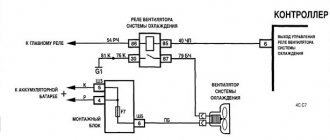
VAZ-21103 engine control circuit with “January-5.1” controller
For reference: the 16-valve design is directly related to the neutralization of harmful emissions, while the 8-valve design has already exhausted its possibilities for modernization. This is supported in every possible way by the manufacturer - just watch the promotional video where these engines comply with EURO 3 requirements.
VAZ-2112 harness diagrams
Instrument panel harness diagram
1, 2, 3, 4 – instrument panel harness pads to the front harness; 5 — block of the instrument panel harness to the side door harness; 6, 7, 8 — instrument panel harness pads to the rear harness; 9 – rear window heating switch; 10 – light signaling switch; 11 – windshield wiper switch; 12 – block of the instrument panel harness to the radio; 13 – mounting block; 14 — instrument cluster; 15 – heater control controller; 16 – heater motor switch; 17 — block of the instrument panel harness to the ignition system harness; 18, 19 — blocks of the instrument panel harness to the air supply box harness; 20 — ignition switch; 21 – fog lamp relay; 22 – sound signal relay; 23 — power window relay; 24 — starter relay; 25 – seat heating relay; 26 – external lighting switch; 27 – fog lamp switch; 28 – cigarette lighter; 29 – lampshade lighting of the glove box; 30 – glove box lighting switch; 31 – switch for rear fog lights; 32 – right steering column switch; 33 – socket for connecting a portable lamp; 34 — instrument lighting switch; 35 – brake signal switch; 36 – sound signal switch; 37 – alarm switch; 38 – air distribution drive gearmotor; 39 – VAZ-2112 illuminator; 40 — instrument panel harness block to the front harness; 41 – trunk lock drive switch; 42 – rear fog light relay.
A – grounding point of the instrument panel harness.
Source
Fuses and relays VAZ 2110
F1 - 5A - License plate lamps. Instrument lighting lamps. Side light indicator lamp. Trunk light. Left side side light lamps F2 - 7.5A - Left headlight (low beam) F3 - 10A - Left headlight (high beam) F4 - 10A - Right fog lamp F5 - 30A - Door window electric motors F6 - 15A - Portable lamp F7 - 20A — Electric motor of the engine cooling system fan. Sound signal F8 - 20A - Rear window heating element. Relay (contacts) for turning on the heated rear window F9 - 20A - Recirculation valve. Windshield and headlight cleaners and washers. Relay (winding) for turning on the heated rear window F10 - 20A - Reserve F11 - 5A - Side light bulbs on the right side F12 - 7.5A - Right headlight (low beam) F13 - 10A - Right headlight (high beam). Indicator lamp for turning on the high beam. F14 - 10A - Left fog lamp F15 - 20A - Electric seat heating. Trunk lock lock F16 - 10A - Relay-breaker for direction indicators and hazard warning lights (in emergency mode). Hazard warning lamp F17 - 7.5A - Interior lighting lamp. Individual backlight lamp. Ignition switch illumination lamp. Brake light bulbs. Clock (or trip computer) F18 - 25A - Glove box lighting lamp. Heater controller. Cigarette lighter F19 - 10A - Door locking. Relay for monitoring the health of brake light lamps and side lights. Direction indicators with warning lamps. Reversing lamps. Generator excitation winding. On-board control system display unit. Instrument cluster. Clock (or trip computer) F20 - 7.5A - Rear fog lamps
K1 – relay for monitoring the health of light bulbs; K2 – front wiper relay; K3 – repeater and alarm relay; K4 – low beam relay; K5 – high beam relay; K6 – additional relay; K7 – relay for turning on the heated rear window; K8 – backup relay
Repair and tuning VAZ
- admin to the post differences between 8v and 16v controllers using the example of January 7.2 8v and Bosch 7.9.7 16v
- admin to post Useful information
- admin to post Atomic soft
- admin to the post Answered questions (comments) over the past months
- admin to the entry Pinout of the connection block SUD M7.9.7./January7.2 to the interior wiring of the Europanel (VAZ 2114)
- admin to the entry Chiptuning - About the table of monitoring stations and control centers (for dummies)
- admin to the post Answer to a question about Atomic Tune 2.8.8
- daser on Angel Eyes
- Kirill on the entry Pinout of the connection block SUD M7.9.7./January7.2 to the interior wiring of the Europanel (VAZ 2114)
- Anonymous to the post Answered questions (comments) in recent months
Basic principles
Regardless of whether your VAZ 2110 has a carburetor or an injector, the basic principles for laying the wiring are the same. Finding a wiring diagram is not at all difficult, the main thing is to understand it. Actually, according to the location, the wiring is under the hood and in the cabin.
Its basic principles are the same, and boil down to the following:
the wire supplying power to the positive terminal of the battery is always braided in red; it is also advisable not to change its color. In all diagrams it is designated as “P”, that is, plus;
In the VAZ 2110, if the battery is connected, all electrical equipment is energized. That is why, in fact, before starting any repair (especially if it is related to the electrical part of the car), it is strongly recommended to disconnect the battery.
VAZ-2110 wiring diagram
Wiring diagram and troubleshooting
Electrical wiring plays one of the important roles in a car. The correct operation of the main devices and systems, as well as the vehicle as a whole, depends on it. Today we will look at the electrical wiring diagrams of the VAZ-2110 family.
Electrical wiring for the VAZ-2110 is of two types: carburetor and injector . There are slight differences, but the basic principles of operation and wiring are the same. Depending on the location, the wiring differs into: under the hood and in the cabin . All electrical equipment of the car is connected using wires of a certain color. Each element has its own wiring harness through the blocks and fuses.
The on-board voltage is 12V constant, minus on the car body.
Having a wiring diagram and knowing the operating principles of the main components of the car is not at all difficult to find the malfunction and the cause of its occurrence.
Before starting to repair the vehicle's electrical wiring (if this is not related to troubleshooting), the terminals should be removed from the battery.
Electrical diagram of a carburetor ignition system
At the first releases of the VAZ-2110, a carburetor was installed, which was later replaced by an injector, as a more modern and reliable system that ensures economical stable operation of the engine. The wiring of an engine with a carburetor includes almost the same vehicle life support systems as with an injector.
A
— the order of conventional numbering of plugs in the blocks of the mounting block, instrument cluster, ignition switch and gear motor of the windshield wiper
B
— the order of conventional numbering of plugs in the blocks of the ignition sensor-distributor and speed sensor
Notes:
1.
In the instrument panel wiring harness, the second ends of the white, black, orange, white with red stripe and yellow with blue stripe wires are connected to each other at the same points.
2.
The bends of the wires at the points of entry into the harness indicate the direction of their laying in the harness.
Electrical diagram of a contactless car ignition system
The carburetor is already an obsolete car part. It is less reliable and cannot provide such an accurate supply of the fuel mixture. In later releases, the carburetor ignition system was replaced with an injection system. The controller in this system “reads” the operation of all systems, thereby determining and setting many indicators - calculation of the fuel mixture, etc.
To find a wiring fault, you need to start looking in the contacts. Moreover, you need to check all the wires that are included in the harness: their visual integrity, resistance, reliability of contacts, etc. The underhood wiring has identical plugs.
In addition to the wiring that is provided for the VAZ 2110 - carburetor, "ten" - injector, it is also equipped with a number of fuses that protect almost all of it from the possibility of short circuiting. The fuse and relay box in VAZ-2110 cars is located in the car interior near the driver's seat, to the left and below the steering wheel.
Fuse box VAZ-2110, VAZ-2111, VAZ-2112
VAZ-2110 fuses (number, rating and what they are responsible for)
Structurally, fuses are not provided only for the supply of current by the wire from the battery, in the car starting and ignition circuit, as well as for the wire going to the generator.
To replace a faulty fuse, first find the one that has blown and be sure to eliminate the cause. After that, install a new one of the same value.
Do not replace fuses with jumpers; this may cause blocks and devices to become unusable, as well as a wiring fire!
F1 - 5A - License plate lamps. Instrument lighting lamps. Side light indicator lamp. Trunk light. Left side marker lamps. F2 - 7.5A - Left headlight (low beam). F3 - 10A - Left headlight (high beam). F4 - 10A - Right fog lamp. F5 - 30A - Electric door window motors. F6 - 15A - Portable lamp. F7 - 20A - Electric motor of the engine cooling system fan. Sound signal. F8 - 20A - Rear window heating element. Relay (contacts) for turning on the heated rear window. F9 - 20A - Recirculation valve. Windshield and headlight cleaners and washers. Relay (coil) for turning on the heated rear window. F10 - 20A - Reserve. F11 - 5A - Starboard side marker lamps. F12 - 7.5A - Right headlight (low beam). F13 - 10A - Right headlight (high beam). Indicator lamp for turning on the high beam. F14 - 10A - Left fog lamp. F15 - 20A - Electric seat heating. Locking the trunk lock. F16 - 10A - Relay-breaker for direction indicators and hazard warning lights (in emergency mode). Hazard warning lamp. F17 - 7.5A - Interior lighting lamp. Individual backlight lamp. Ignition switch illumination lamp. Brake light bulbs. Clock (trip computer). F18 - 25A - Glove box lighting lamp. Heater controller. Cigarette lighter. F19 - 10A - Door locking. Relay for monitoring the health of brake light lamps and side lights. Direction indicators with warning lamps. Reversing lamps. Generator excitation winding. On-board control system display unit. Instrument cluster. Clock (or trip computer). F20 - 7.5A - Rear fog lamps.
Fuse box relay (number and what includes)
K1 – relay for monitoring the health of light bulbs; K2 – front wiper relay; K3 – repeater and alarm relay; K4 – low beam relay; K5 – high beam relay; K6 – additional relay; K7 – relay for turning on the heated rear window; K8 – backup relay (not installed on 110 series vehicles);
Ignition and engine control circuit
Here are the control diagrams for the following internal combustion engines:
- 21120 – January 5.1 or BOSCH M1.5.4N, Euro-2;
| Motor | 21120 (Euro-2) | 21124 (Euro-2) | 21124 (Euro-3) |
| Injectors | 1 | 2 | 2 |
| Ignition coil | — | 1 | 1 |
| Candles | 2 | — | — |
| Ignition module | 3 | — | — |
| Diagnostic connector | 4 | B | B |
| ECU | 5 | 3 | 3 |
| Tidy taps | 6 | E | E |
| Ignition relay (6) | 7 | 4 | 4 |
| Ignition fuse (1) | 8 | 5 | 5 |
| Fan relay (4) | 9 | 6 | 6 |
| Fan fuse (2) | 10 | 7 | 7 |
| Fuel pump relay (5) | 11 | 8 | 8 |
| Fuel pump fuse (3) | 12 | 9 | 9 |
| Mass air flow sensor | 13 | 10 | 10 |
| Rough road sensor | — | — | 11 |
| TPDZ | 14 | 11 | 12 |
| DTOZH | 15 | 12 | 13 |
| RXX | 16 | 17 | 14 |
| Lambda probe main | 17 | 14 | 15 |
| Additional lambda probe | — | — | 16 |
| Knock sensor | 18 | 15 | 18 |
| DPKV | 19 | 16 | 19 |
| Canister purge valve | 20 | 13 | 17 |
| APS block | 21 | 18 | 20 |
| APS indicator | 22 | 19 | 21 |
| Speed sensor | 23 | 21 | 23 |
| Fuel pump + level sensor | 24 | 22 | 24 |
| Oil pressure sensor | 25 | 23 | 25 |
| Antifreeze thermometer sensor | 26 | 24 | 26 |
| Oil level sensor | 27 | — | — |
| Phase sensor | 28 | 20 | 22 |
| ABS connector | A | A | A |
| Air conditioner connector | B | IN | IN |
| Fan connector | C | — | — |
| Illumination of the ignition switch (to the blue-white wire) | D+E | — | — |
| Bends to the door harness | — | D | D |
| + battery | F | G | G |
| Weight | G1+G2 | G1+G2 | G1+G2 |
The elements installed in the additional mounting block are indicated in brackets.
Mounting block on the right side under the dashboard
General information
The car and electricity are fused together from the very beginning. You may recall that the very first such vehicle used an electric motor, until the internal combustion engine was invented.
Wiring a VAZ 2112 makes it possible to perform actions that simply cannot be carried out without electricity.
- ignition of the fuel mixture in the cylinders of a carburetor and injection engine;
- starting the engine;
- operation of head lighting devices at night to illuminate the road surface;
- fog lights when driving in conditions of limited visibility;
- light indication of the instrument scale;
- side lights for vehicle detection at night;
- turn indicators;
- signaling devices.
Schematic diagram of the electrical wiring of a VAZ 2112 car (16 valve)
In addition, the wiring diagram of the VAZ 2112 will help you figure out how and what the auxiliary equipment is connected to:
- “wipers”, which allow the driver to feel normal in rainy or snowy weather;
- sound signals in case of an emergency;
- searching for a spark in case of engine failure;
- CD player and radio;
- window lifters;
- windshield and rear window heaters;
- interior lighting lamps.
The electrical wiring of the VAZ 2112 connects electrical appliances and devices with current sources located in the car. An electrical equipment system is a collection of current consumers and its producers .
Serviced battery
Car power supplies and ignition
Let's take a closer look at it, starting with the most important elements:
A rechargeable battery is a chemical source of energy, which is a lead-acid DC battery module. The photo shows a battery being serviced. Usually there are six of them.
- starting the engine with an electric starter;
- supplying power to electrical equipment when the engine is not running or when it is running at low crankshaft speeds.
Generator . Used as the main source of current for all electronic and electrical devices and instruments in the car. But, it can provide this only at medium or high crankshaft speeds. The price of this equipment depends on the manufacturer.
Ignition system . Designed to ignite fuel in engine cylinders. Can be contact or non-contact. Modern VAZ 2112 cars are equipped with the latter version, which has a number of advantages over the contact system, which is already considered obsolete.
The main advantages should be noted:
- increased voltage potential supplied to the secondary winding of the ignition coil;
- increased power and longer spark discharge duration;
- increased service life of the spark plug;
- the breaker contacts practically do not fail;
- fuel burns better in the cylinders, which saves money as a result;
- makes engine starting easier;
- the engine becomes more responsive and more economical.
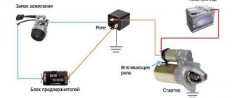
Starter relay installation diagram
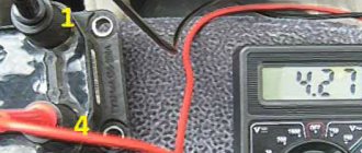
If the battery is not charging
When the battery is no longer charged, it does not allow the car to be used for a long time. Maximum until it is completely discharged. In this case, a red light comes on on the instrument panel, which signals that the wiring on the VAZ 2112 requires checking.
The instructions below will help with this:
- Check the generator drive belt, it should be intact and have the required tension.
Advice: it is not recommended to apply too much tension; it will significantly shorten the life of the belt.
- If everything is fine, check the fuse. The VAZ 2112 wiring diagram for 8 or 16 valves, as well as the reverse side of the mounting block cover, will help you find out where it is located. After replacing it and starting the engine, the lamp should go out, allowing you to continue your journey.
Checking and replacing the fuse
- When the charging lamp does not go out, check the wire from the generator to the “+” terminal of the battery. There are usually two of them:
- thick – from the battery to the starter,
- thin - to the generator.
It should not be broken or have oxidized contacts . It happens that there is no way to fix the breakdown, which means that the generator itself needs to be repaired. Repairs must not be delayed as a short circuit may occur. But it’s better to do this at a service station or at home in the garage with your own hands.
Advice: when driving only on battery power, to reduce on-board electricity consumption, turn off as many devices as possible - radio, heater fan, etc.
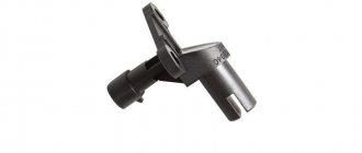
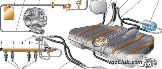
1 - ignition relay; 2 — ignition switch; 3 - battery; 4 - neutralizer; 5 — oxygen concentration sensor; 6 — adsorber with solenoid valve; 7 — air filter; 8 — mass air flow sensor; 9 — idle speed regulator; 10 — throttle position sensor; 11 — throttle assembly; 12 — diagnostic block; 13 — tachometer; 14 — speedometer; 15 — control lamp “CHECK ENGINE”; 16 — immobilizer control unit; 17- ignition module; 18 — nozzle; 19 — fuel pressure regulator; 20 - phase sensor; 21 — coolant temperature sensor; 22 — spark plug; 23 — crankshaft position sensor; 24 — knock sensor; 25 — fuel filter; 26 - controller 2112; 27 — fan switching relay; 28 — electric fan of the cooling system; 29 — relay for turning on the electric fuel pump; 30 — fuel tank; 31 — electric fuel pump with fuel level indicator sensor; 32 — gasoline vapor separator; 33 - gravity valve; 34 - safety valve; 35 — speed sensor VAZ-2112; 36 - two-way valve.
The VAZ-2112 engines and some VAZ-2111 engines are equipped with a distributed phased injection system: fuel is supplied alternately by injectors in accordance with the operating order of the cylinders, which reduces the toxicity of exhaust gases. In this case, a phase sensor is installed on the cylinder head, and a disk with a slot in the rim is installed on the camshaft pulley.
Electrical connection diagram of the ECM Russia-83 Bosch 1.5.4, January 5.1.2 VAZ-21103, 21113, 2112
- — nozzles;
- - spark plug;
- — ignition module;
- — diagnostic block;
- — controller;
- — block connected to the instrument panel harness;
- — main relay;
- — main relay fuse;
- — electric fan relay;
- — controller power supply fuse;
- — electric fuel pump relay;
- — fuse for the power supply circuit of the electric fuel pump;
- — mass air flow sensor;
- — throttle position sensor;
- — coolant temperature sensor;
- — idle speed regulator;
- - knock sensor;
- — crankshaft position sensor;
- — camshaft position sensor (phases);
- — APS control unit;
- — APS status indicator;
- - speed sensor;
- — electric fuel pump with fuel level sensor;
- — oil pressure warning lamp sensor;
- — coolant temperature indicator sensor;
- — oil level sensor;
- - block connected to the ignition system harness;
- — instrument cluster;
- — mounting block;
- — electric cooling system fan;
- — ignition switch;
A - block connected to the ABS cabin group harness; B - block connected to the air conditioner harness; C — block connected to block R of the front harness; D — wire connected to the ignition switch (backlight); E - block connected to the blue-white wires disconnected from the ignition switch; F - to the “+” terminal of the battery; G1, G2 - grounding points; L — contacts of the block to the trip computer; M - contact of the block to the on-board control system unit; N — contacts of the instrument panel harness block and the front harness; R — block connected to block C of the ignition system harness; Z - to the “B+” terminal of the VAZ-2112 car generator.
Electrical connection diagram for VAZ 2114, additional segment
Here are grouped auxiliary equipment that is not related to the power plant or on-board computer of the car:
- 1 – contact group of wiring from the doors to the instrument panel block;
- 2 – a similar terminal intended for connecting heated seat devices for the driver and front passenger;
- 3/4 – central locking drive, sections of the front left and right doors, respectively;
- 5/6 – contact blocks of the front right and left speakers, respectively;
- 7 – electronic central locking control unit;
- 8/9 – connecting door parts of electrical equipment to the auxiliary left beam;
- 10 – terminal for connecting the standard speaker system;
- 11 – “mother” of doors to the right wiring harness for connecting electrical equipment;
- A1 – connection of grounding electrical wiring.
Physically, the output is connected to the dashboard, with a contact group located near the hood opening handle. The corresponding fuse is also located here.
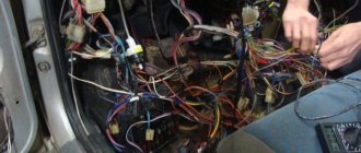
Replacing the wiring harness in the rear of the car
The vehicle manual warns that harsh climatic operating conditions have a negative impact on the vehicle's electrical components. And electrical connectors and wires are among the first to suffer. And since the price of parts is low, the car owner can replace:
- Collapsed terminal block;
- Wire with damaged insulation;
- Components and devices approved for installation from other models of the VAZ family.
Advice: for this you need a VAZ 2112 wiring diagram with decoding in order to clearly understand which electrical circuit is responsible for what and controls what.
Rear Harness Terminal Blocks
Let's take a closer look at the above diagram:
- common terminal block of the wiring harness for connecting the wiring coming from the instrument panel (in the diagram under No. 1);
- terminal block of the wiring harness for connection with the wiring of the instrument panel of cars in the “standard” configuration and for connection to the side door harness for cars in the “luxury” configuration (in diagram No. 2);
- rear harness terminal block for connection to the instrument panel harness (No. 3);
- two 4-pin terminal blocks (for modifications 2112-3724558-10 16 valves). Indicated on the diagram as No. 4 and No. 5;
- side direction indicators (no. 6 – left, no. 7 – right);
- power supply to the individual lighting lamp (number 8 on the diagram);
- power supply for the general interior lighting lamp (No. 9);
- handbrake sensor connector (No. 11);
- rear lights (in the diagram No. 11 is left, No. 12 is right);
- interior temperature sensor connector (No. 13 in the diagram);
- connector for connecting 4 interior dome light switches (in the diagram under numbers 14,15,16 and 17);
- connector for trunk light (No. 18);
- reserve block of the wiring harness (in diagram No. 19). Can be used as a connector to connect to the side door wiring harness;
- block for connecting the wiring harness of the license plate lights (no. 20 in the diagram);
- The wiring grounding points are indicated in the diagram as A and A1.
Wiring an additional wiring harness for VAZ 2112
Individual parts of the wiring can also be replaced with your own hands. Specifically, an additional wiring harness in the trunk of the car (pictured below).
It connects to the mains:
- rear window heating system;
- electric rear wiper gear;
- additional brake light;
- trunk lock electric motor.
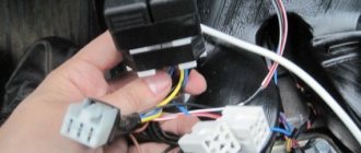
The VAZ 2112 electrical wiring of this wiring harness has the following designations:
- Through the terminal block No. 1, the wiring harness is connected to the main wiring of the car. Includes 4 wires: red, yellow-blue, white-blue and pink-black;
- Block No. 2 is similar in functionality. Uses wires: green, white, black and red;
- Terminal No. 3 is responsible for the operation of the electric motor unit and the rear window wiper gearbox. The contacts are powered by 4 wires: black, pink-black, yellow-blue and white-blue;
- terminal blocks No. 4 and 5 are responsible for connecting the rear lights;
- Terminal No. 6 powers the trunk lock motor. Wires – white and black;
- terminal block No. 7 is responsible for connecting the heated rear window (two red wires);
- the additional brake light is powered from terminal block No. 8 (wires black and red).
Installation of fog lights
Car owners can independently equip their car with fog lights. To make installation easier, you can watch videos from forums where craftsmen share their experience of such work.
Wiring VAZ 2112 for fog lights (Luxury package)
Conclusions: in fact, replacing old wiring in the rear of a car is much easier than in the engine compartment or inside the cabin. And the diagrams proposed in the article will help you figure it out faster and avoid mistakes.
Let's also understand the wiring diagram of the VAZ 2107.
Information that a motorist must know before replacing existing wiring
First of all, the car owner must know when and in what cases the car wiring is replaced. At the same time, it is also necessary to have information about the final operational life in order to objectively understand when the wiring may need to be replaced. List of the most common reasons that cause wiring to malfunction:
- the appearance of cracks in insulation during a long period of operation;
- oxidation;
- corrosion;
- fuse blown, etc.
Components needed to perform wiring replacement:
- multivariate set of wires;
- fuse block for VAZ 21104;
- housing for the heating system;
- various types of sensors: brake fluid, cooling system, etc.;
- pads;
- many terminals;
- Of course, it goes without saying, duct tape.
A practical look at rewiring
Replacing wiring on a VAZ 2110
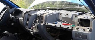
So, a detailed step-by-step algorithm for replacing the wiring:
- first you need to dismantle the front part of the cabin;
- then you can deal with the proper degree of isolation, if there is a desire for it;
- after which, you need to pay special attention to the front headlight switch;
- The windshield wiper (see Replacing windshield wipers on a VAZ 2110 on your own) operates using its own mini-motor, the wiring of which must be checked for serviceability, since very often it simply becomes acidified;
- understand all heating modes;
- the connection of all electronic devices must be carried out strictly sequentially, by increasing the number of connected wires.
Note. Before disconnecting all electronic devices, it is necessary to draw your own conventional electrical circuit by hand in order to correctly make the appropriate connections in the future.
- now it’s time to tackle the fuse blocks, or rather their installation;
- most wires exceed the required length, so they simply do not fit into the allotted space;
- the bracket is the most rational solution to the problem; it will allow you to successfully replace the fuses with new ones;
- with the installation of a new fuse, the position of the front light indicator light, as well as the emergency warning light, will change;
- the heater will also have to be affected: first you need to remove the old radiator and then disassemble it to make it possible to replace the fan;
- Assembly is carried out strictly in reverse order.
Note. Before you begin the wiring replacement procedure, you need to find its current diagram. Otherwise, during the process of assembly and disassembly, you can quickly get confused, and you will have to send the car to a car service center.
Electrical diagram for VAZ 2110
The main advantages of the new wiring:
- the emergence of a practical opportunity to connect any gadget;
- longer service life compared to old wiring;
- high degree of reliability of everyday functioning;
- improving the quality and stability of electronic devices and much more.
Replacement of electrical wiring of VAZ 2110
It is always necessary to remember that installing homemade wiring is an easily feasible technical manipulation; the main thing is to understand all the necessary nuances.
Latest publications
The interior heater of the VAZ-2110 (Heater), in comparison with previously produced car models of this car plant, has become a structurally more complex device. In his circuit, the valve that shuts off the supply of coolant to the heater radiator has disappeared, so it is constantly hot. The radiator is located horizontally and to remove air or steam from it, there is a steam outlet in its left tank. The air flow is controlled by two dampers driven by a micro motor. The entire work process is controlled by an electronic unit, which receives information from a temperature sensor installed next to the interior lighting lamp.
If we look at the statistics, the most likely causes of malfunctions in the stove on the VAZ 2110 can be: control unit, micro motor, fan, cabin temperature sensor, heater dampers. It was in this sequence that the stove malfunctions were located, after a survey of VAZ-2110 car owners.
Most car owners can only check if the control unit is faulty by replacing it with a known-good unit. At the same time, they should know that the “tens” that are currently in use can have four types of control units. Their markings are as follows: 1303.3854, 1313.3854, 1333.3854, 1323.3854. The first three blocks are interchangeable and can be installed on heaters 2110-8101012 and 2110-8101012-01. But the latest control unit began to be installed in 2003 on the stove 2111-8101012
That is, now, if you paid attention to the markings, on the “tens” there is a stove from a VAZ-2111.
The cabin temperature sensor is not difficult to get from the installation site. There is a mini fan on it and if you put the control unit in the “MIN” (blue dot) or “MAX” (red dot) position, it should not rotate. You can also check the functionality of the stove by replacing it with a working sensor.
Other faults may be located only inside the heater and cannot be eliminated without partial or complete disassembly. This applies to the micro motor and its shaft position sensor, as well as two dampers that distribute the flow of cold and warm air. In addition, AVTOVAZ does not recommend repairing the heater yourself. Well, you probably already know about such malfunctions of the cooling system as insufficient antifreeze level or failure of the thermostat, which affect the operation of the stove.
Sources
- https://gold.doitwork.ru/skachat-ventiljator-pechki-vaz-2112-novogo-obraztsa.html
- https://helping-auto.ru/vaz/2110/pochemu-ne-rabotaet-pechka-na-vaz-2110/