The VAZ-2123 SUV was produced in small series at AvtoVAZ OJSC from 1998 to 2002 as an improved Niva 2121. Then GM-AvtoVAZ began producing a new car called Chevrolet Niva. In addition to the basic five-door station wagon body, there were modifications with a pickup body (VAZ-2323) and a van (VAZ-2723). The injection engine was a further development of the VAZ-21214 engine, with a volume of 1.7 liters and a power of 79.6 horsepower.
Electrical wiring components
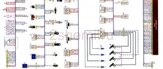
The standard Niva Chevrolet wiring diagram is divided into several sections for better maintainability and ease of maintenance.
- Front part - a set of cables connects all equipment located in the engine compartment of the car.
- The interior part - the unit is additionally divided into independent zones, which allows you to power different groups of equipment without the risk of damaging or overloading the main elements.
- Instrument panel compartment - a bundle of cables combines the lines from all gauges, sensors and indicators.
- The stern assembly - the bundle is responsible for voltage and control of equipment located on the rear side of the vehicle.
About the main elements of an electrical circuit
The vehicle's electrical circuit includes the following components:
- Sources of electrical energy.
- Devices responsible for its consumption.
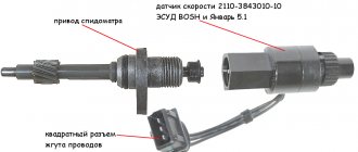
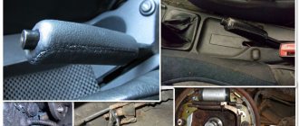
The main location of the block is to the left of the steering column. The device is closed from below with a special lid. You only need to unscrew two screws to get to the internal contents. After this, squeeze out the upper edge of the lid, gradually freeing this part from all fasteners. The entire connection diagram for the VAZ 2123 speed sensor and other devices becomes available.
A block will appear, which is held on a special bracket. Depending on the configuration and year of manufacture, the circuit itself varies, as does the total number of fuses.
Video instructions for replacement:
A fairly common option: “It’s getting cold outside. I got into the car, started it, and the car immediately stalled!” My first thought was “the fuel pump is broken.” The starter spins briskly, but doesn't grab a beat.
0) When the car is working properly, when you turn the ignition key, you hear a click from the fuel pump relay (under the glove compartment, at the passenger’s feet), after which the fuel pump hums for 4-6 seconds (increases pressure), after which the relay clicks again. Also, the relay and pump operation can be heard while the starter is running. (But due to the operation of the starter itself, it is very quiet).
In my case, the relay was audible, but the pump was silent.
But you should keep in mind that clicks and the pump will only be heard the first 2 turns of the key. After this, Boshev’s “brains” block the work of pressure, it is believed that there is pressure in the system.
Pinout of Niva Chevrolet connectors responsible for the front part of the wiring
- 1/6 – front right/left headlight block;
- 2 – joint assembly of the machine starter;
- 3 – voltage supply for traction starter;
- 4 – battery connection terminals;
- 5 – generator module for powering the electrical circuit;
- 7/15 – units for combining head optics fog lights;
- 8 – contact group for the drive of the electric motor for the front windshield washer;
- 9 – input of a temperature sensor that measures indicators outside the vehicle;
- 10 – contact plug for the engine compartment lighting lamp;
- 12 – standard sensor for measuring the remaining brake fluid level;
- 13 – plug of the standard electric motor for driving the windshield wiper;
- 14 – designation of a standard horn;
- 16/17 – plug inputs to the dashboard.
Chevrolet Niva wiring diagram, part of the ECM
- 1 – spark plug pins;
- 2 – contact group of injector drivers;
- 3 – ignition unit;
- 4 – control controller;
- 5 – main protective relay of the internal combustion engine;
- 6 – area for location of fuse links;
- 7 – main relay fuse;
- 8/9 – protective circuits of the right and left head fans of the radiator;
- 10 – protective element for the control fuse of the main fuel pump;
- 11 – controller circuit fuse;
- 12 – secondary protective element of the main radiator fan on the right side;
- 13 – auxiliary fuse of the above circuit;
- 14 – fusible link of the fuel pump control circuit;
- 15 – fan of the main radiator, located on the left side;
- 16 – standard oxygen concentration sensor in the intake manifold;
- 17 – drain output of the detonation channel meter;
- 18 – DPKV output;
- 19 – control by the adsorber purge valve;
- 20 – output of the mass air flow sensor group;
- 21 – idle speed control drive;
- 22/23 – activation of the left/right fan motor of the main engine cooling system;
- 24 – auxiliary resistor;
- 25 – control of the TPS device;
- 26 – output from antifreeze temperature sensor;
- 27 – status indicator of the above-described sensor;
- 28 – standard module for measuring lubricant pressure in the crankcase compartment of the power plant;
- A/B – battery terminal blocks;
- C – “mother” input for connecting to the dashboard;
- G1/G2 – grounding outputs of the wiring section.
Also interesting: The principle of operation of the air conditioner of a Niva Chevrolet car
Causes of fuse failure
Each element is designed for a specific current. Its meaning is written on the case, but for convenience, the colors of the case correspond to certain values.
- Brown – 7.5 A
- Red – 10 A;
- Blue – 15 A
- Yellow – 20 A;
- White – 25 A.
If the permissible current value is exceeded, the fuse blows and the circuit opens. In this way, consumer failure is prevented. The reason for the increase in current strength may be an increase in the circuit load or a short circuit. In this case, the total resistance of the circuit decreases, and the current increases.
Relay and fuse locations
The main part of the fuses is located inside the cabin, under the panel to the left of the steering column. There are four blocks in total:
- Engine control system fuses.
- Windshield wiper.
- General fuses.
- The engine management system, which is always complemented by the Chevy Niva circuit.
The last block is located at the bottom.
The main and additional blocks are always connected to each other. 10 fuses are included in the top block. There are six of them in the lower one. Cooling works, among other things, due to such a device.
The relay box for the engine management system is located below the main, additional fuse box. There are a total of five relays and one fuse in this part. Sometimes the so-called starter relay is additionally included in the circuit; the year of manufacture becomes the determining factor.
There are also mounting blocks, which are also located to the right or left of the steering column.
Replacing fuses
Before replacing an element, it is necessary to eliminate the cause of its failure. Do not use fuses of a different rating. The calculated current strength for each circuit can be found in the assignment table located above in the article.
The protective device may fail due to long periods of use, so if any consumer stops working, the first thing to check is its fuse.
They are held in their nests by sliding contacts. In order to remove the element, simply pull it out of the socket. To make this more convenient, modern mounting blocks are equipped with plastic tweezers.
A faulty fuse can be determined by visual inspection or using an ohmmeter. Since the housings are made of transparent plastic, the integrity of the conductor is easy to determine with the naked eye. In addition, conductor burnout is accompanied by an increase in temperature. Traces of heat exposure remain on the plastic case. Having selected an element suitable for its nominal value, it is inserted into the socket in place of the failed one.
In no case should you use bugs instead of a fuse, as they may not burn out when the current increases, which will lead to overheating and fire of the wiring.
If a fuse burns out on the road, you can replace it with an identical one that protects the circuit of the consumer that is not currently in use.
More information about Chevrolet Niva electronics can be found here.
Chevrolet Niva is a Russian-assembled compact crossover. Produced in 2002, 2003, 2004, 2005, 2006, 2007, 2008. In 2009, the car received a restyling. The updated version was produced in 2010, 2011, 2012, 2013, 2014, 2015, 2016, 2022 and 2018. We will look at a block with Chevrolet Niva fuses and relays with a full description of the presented circuits. Let's show you where the cigarette lighter fuse is located.
p, blockquote 1,0,0,0,0 —>
p, blockquote 2,0,0,0,0 —>
Niva electrical circuit responsible for the equipment built into the front doors
The following is a general breakdown of the electrical equipment of Chevrolet Niva car doors manufactured after 2009. The representation is based on the fact that both sides are almost identical:
- 1/10 – door position limit switches;
- 2/11 – drive of electric window regulator gearboxes;
- 3/12 – plugs for control drives for adjusting the position of rear-view mirrors;
- 4/13 – door lock gearboxes;
- 5/14 – standard terminal blocks for the speaker outputs of the standard acoustic module;
- 6/15 – window switch drives.
The NIVA electrical circuit is responsible for powering the equipment built into the rear doors
Here all the equipment is also mirrored. The elements and wiring completely duplicate the opposite side:
- 1/2 – outputs for the aft cable harness;
- 3/6 – terminal block for powering the door lock gear motor;
- 4/5 – door position limit switches.
- 1 – main lighting device;
- 2 – fuse box;
- 3 – headlight switching regulator;
- 4 – part of turning off the ignition;
- 5 – headlight switches;
- 6 – designation in the instrument cluster of the area responsible for turning on the high beam;
- K4/5 – protective relays for turning on the high- and low-range modes of the head optics;
- A – terminal pins going to the circuit’s power source.
Electrical Harness System
Due to the ignition system, a spark appears in the cylinders corresponding to the current power strokes. In modern engines, wires go to sensors that are responsible for monitoring several indicators:
- Motor temperature.
- Ignition, and so on. The injector also becomes an important part.
The ignition system harness is in most cases connected to several other parts:
- controller;
- instrument panels;
- "mass".
Next, the wires are sent to the rear harness. Moving on to the engine compartment, the main harness splits into two wires. Of these, the largest is sent to the radiator, connecting with the following components along the way:
- DMRV.
- Crankshaft sensor.
- Resistor.
- Electric fans.
Through the power steering pump, other wires are thrown from the core, going to additional sensors:
- phases;
- idle move;
- throttle valve;
- detonation;
- injectors - a fuse for them is not added to the system.
Due to the wiring, the operation of the engine is clearly controlled. Ensures uninterrupted operation regardless of environmental conditions.
The second core goes up, after which it is divided into two parts. The wires to the plus and minus go to the right. The battery is also located there. To the left they connect to the adsorber, fuel pressure sensor and oxygen sensor. This is how electrical wiring is arranged in most cases.
Also interesting: Platform for a winch with protection for Niva 2121, 2131 and their modifications
A branch from the harness may go to the air conditioning fuse if the car is equipped with such equipment.
If even one part of this system shorts, there is a high probability that the engine simply will not start. The controller stops seeing information regarding temperature, fuel supply to the injectors, and throttle valve position.
Under such circumstances, it is better not to resort to diagnostics, but to replace the entire harness at once. It may take too much time to find one wire, and the result will be questionable. The wiring works better when new.
What is a relay
A relay is called an electromagnetic switch, which is designed for switching during abrupt changes in the input value (current, voltage) in electrical circuits. In simple terms, it is a device that turns on when a voltage signal is applied to it, and turns off when the voltage disappears. The current that switches the device is very low, and to start the fuel pump a large current is required. Therefore, it is also called a kind of amplifier.
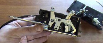
What does it consist of?
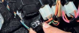
There are different numbers of relays, but almost all of them perform similar functions. This device consists of a contact group, which we can see by removing it from the block. Inside it there is a coil with a certain number of turns of copper wire, a return spring and an armature. All this is assembled in a certain sequence and located on the board. A photo of the contact group and the shape of the relay can be seen below, or you can enter it in a search engine and see all the types and types. We are interested in the Chevrolet Niva fuel pump relay, which looks like this.
Relay operating principle. The fuel pump relay is used only in engines with injection type. Carburetor engines use a mechanical fuel pump. The Niva (injection) car uses a 12V electric fuel pump. The electrical circuit of its operation includes power wires, a fuse, a relay, as well as fuel reading sensors in the tank. Thus, when you turn the car key, power is automatically supplied to the relay. It, in turn, operates instantly and closes the contacts that power the pump. This is how the fuel pump turns on briefly, as a result of which, when we sit behind the wheel and turn the key, we hear its buzzing, indicating its operation.
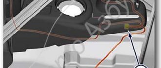
Location in Niva
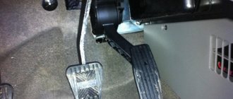
On the right side under the glove compartment there is a cover, and under it there is part of the electronics of the Niva car, the second part is under the dashboard on the driver’s side. Under this cover you can see the location of four relays. The device that is responsible for turning on the fuel pump and its operation is located under the third number. Next to it is a 15A fuse, which is designed to protect the circuit and electrical components of the fuel pump.
location of the relay box in the car
Connection between battery and starter
Each car has its own starter installation scheme. There may be several access options:
- on right;
- left;
- from the radiator side;
- from the salon side.
It is often necessary to use a lift or inspection hole to reach this component. The mechanism is needed to ensure engagement between the gear and the flywheel. Therefore, the device is most often located in the area where the clutch housing is attached. The electronic version is no exception.
For connection, only one connector is used, to which a special terminal is added. The starter starts working every time the owner turns the key.
It is best to use a multimeter to detect breakdowns in one of these parts of the car. But faults can be easily determined using other simple manipulations.
In most cases, repairing the starter is possible, even if such an important part as the windings has failed. The electrical equipment of a car in most areas is subject to complete restoration.
FakeHeader
Mounting block. The gear motor turns off when the glass reaches one of the extreme positions. The second terminals of the connectors are connected to the body - ground. Therefore, it is very important to have this cheat sheet in your car, but many people underestimate the importance of having this instruction until they encounter problems with the electronic components of their car. The schematic diagram serves as the basis for identifying faults in various components of the Chevrolet Niva SUV.
Instrument cluster. The electrical circuit diagram of a car is a useful map for the driver, with the help of which it will not be difficult to find any malfunction. Fog light switch. Therefore, it is very important to have this cheat sheet in your car, but many people underestimate the importance of having this instruction until they encounter problems with the electronic components of their car. The switch is in the driver's door pillar. Practice shows that the VAZ solution for power supply systems has two qualities that are most important for the automotive industry: simplicity and reliability. This arrangement increases safety and also simplifies maintenance.
Glove box light switch. Connection block to the wiring harness of the front seat heating system. Niva Chevrolet connecting towbar socket
Instrument panel pinout
Here is a description of the terminals and terminals of standard instrument panel wiring:
- 1 – diagnostic output, located on the underside of the board under the steering wheel;
- 2 – plug connector for connecting the ECM;
- 3/4 – standard modules for connecting the front connection of the cores responsible for the engine control systems;
- 5/7 – left and right steering column switches;
- 6 – ignition switch device connector;
- 8 – instrument panel combination;
- 9 – output for powering the connector of the contact group of the interior ventilation and heating system;
- 10/11 – lighting plugs for the above equipment;
- 12 – button switch of the alarm device;
- 13 – mounting box for fuse insertion;
- 14/15 – the lamp itself and the button to turn off the lighting of the glove compartment;
- 16 – contact pin for turning off the brake lights;
- 17 – switch of the standard sound warning module (horn);
- 18 – automatic protection of fog lights of head optics;
- 19 – automatic window lifters;
- 20 – protective relay for sound signal;
- 21 – safety module for the seat heating system;
- 22 – starter control relay;
- 23 – switch for the external lighting system;
- 24 – contact group for connecting the stove fan;
- 25 – built-in switch for turning on the heated windshield;
- 26 – device for turning off the front fog lights;
- 27 – switch for stern lights, fog lighting group;
- 28 – air conditioner setting button;
- 29 – position regulator of heating manipulators;
- 30 – cigarette lighter pin;
- 31 – buttons for adjusting the direction of the light flux of the head optics;
- 32 – adjust the brightness of the instrument panel illumination;
- 33 – auxiliary resistor mechanism of the heating fan;
- 34 – standard immobilizer module;
- 35/36 – standard-type onboard acoustic module terminals;
- 37/38 – terminal connectors for connecting the rear harness of the on-board circuit.
Also interesting: Niva Chevrolet installation of air conditioning - Auto workshop online
Fog light
The diagram for switching on the fog light is shown in Fig. 7-23. The fog lamps 3 in the rear lights are switched on by switch 4 through the APS control unit 5 only if the headlights are on (the corresponding key of the exterior lighting switch 2 is fully pressed). When the side lights are turned off, the rear fog lights turn off automatically.
Rice. 7-23. Diagram for switching on fog lights:
1 - ignition switch; 2 — external lighting switch; 3 — fog lamps in the rear lights; 4 — switch for rear fog lights; 5 — control unit of the automobile anti-theft system.
Pinout of contacts of the Niva Chevrolet fuse mounting block
The car is supplied to the market with several types of mounting blocks. The exact type of device depends on the configuration of the vehicle and its year of manufacture. Further description is given using the example of Bosch M,1,5,4:
- 1 – cylinder ignition system;
- 2 – empty;
- 3 – fuel pump connection contact;
- 4 – stepper motor;
- 5 – free;
- 6 – connection of the main power plant cooling fuse;
- 7 – incoming pulse from the MRI;
- 8 – empty;
- 9 – standard speedometer;
- 10 – not busy;
- 11 – knock sensor;
- 12 – voltage supply for sensors;
- 13 – L-line;
- 14 – weight on the body from the injectors;
- 15 – control of injector drives for cylinders 1-4;
- 16/17 – not used;
- 18 – power supply of devices from 12 volts;
- 19 – common ground cable for electrical appliances;
- 20 – ignition supply to cylinders 2 and 3;
- 21 – stepper motor terminal;
- 22 – engine check lamp;
- 23 – empty;
- 24 – mass of the stepper motor;
- 25 – air conditioning system relay output;
- 26/29 – stepper power plant;
- 27 – voltage to terminal No. 15 of the ignition switch;
- 28 – empty;
- 30 – mass of motor control sensors;
- 31/32 – not applicable;
- 33 – control of settings of injector drivers for cylinders No. 2/3;
- 34-36 – empty;
- 37 – device for powering the main relay;
- 38-40 – not used;
- 41 – submitting a request for an air conditioning module inside the cabin;
- 42 – empty;
- 43 – tachometer control signal;
- 44 – signal supply from the potentiometer;
- 45 – DTOZH;
- 46 – control of the main relay;
- 47 – device for confirming admission to ECU programming;
- 48 – low level of impulse from DPKV;
- 49 – opposite meaning;
- 50-52 – empty;
- 53 – receiving an impulse from the TPS;
- 54 – fuel consumption detail;
- 55 – K-line.
Prevention
To prevent breakdowns, the manufacturer recommends following several tips.
- Once a year, treat all terminals and connectors with special oil - this will prevent the formation of oxides.
- Periodically check the tightness of the contact connectors. If the connections are loosened, short circuits may form or the conductivity of the circuit may decrease, which will be perceived by the ECU as a mechanism failure.
- Check the degree of wear of power cables and lines. During active use of the vehicle, braids made of flexible polymer may wear out and crack. This circumstance can provoke short circuits and mechanical shedding of insulators. Therefore, it is better to prevent a breakdown than to fix it.
If you adhere to the above rules, the car will serve for a long time and with high quality all the time.
Read news about the new Niva
- Electrical diagram of Niva Chevrolet: electrical wiring diagram of VAZ 2123, Chevrolet Niva, electrical diagram and connection of speed sensor, charging with description
- Pump for Chevrolet Niva - Auto workshop online
- Niva Chevrolet installation of air conditioning - Auto magazine MyDucato
- Niva Chevrolet installation of air conditioning - Auto magazine MyDucato
- Why the Chevrolet Niva air conditioner does not turn on: reasons and installation (diagram), belt replacement
- Niva Chevrolet installation of air conditioning - Auto magazine MyDucato
- Niva Chevrolet air conditioning installation - Online auto workshop
- Replacing a Chevrolet Niva heater radiator with air conditioning without removing the panel