Power supply for electrical equipment
Electrical equipment installed on Niva receives power from the main elements of the system:
- if the engine is not running, the current is supplied by a battery installed in a special compartment;
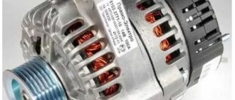
- As soon as the power unit starts, the electrical alternator takes over control. It is equipped with all necessary protection mechanisms, a rectifier and an electronic output voltage regulator.
The battery, which is used when the engine is turned off, begins to restore its charge when it starts and does not take part in any processes.
Maintenance of wiring VAZ 21214 and other Niva models injector and carburetor: electrical diagram
Every modern car today is equipped with an electrical part. The electrical diagram of the VAZ 21214 Niva injector allows, if necessary, to find all the elements included in the on-board network, which is especially important when faults occur in the wiring. Everything a driver needs to know about electrics in domestic SUVs is described in this article.
Detailed electrical diagram of Niva
The wiring diagram may vary slightly depending on the design features of the vehicle.
First, let's look at the index notation:
- VAZ 21213. This index designates a vehicle equipped with a carburetor. The volume of the power unit is 1.7 liters.
- 21214. In VAZ 21214 cars, the scheme involves the use of a similar engine with the same volume. The only difference is that the car is equipped with a fuel injection system.
- There is another model with the index 21213. In VAZ 21213 cars, the electrical circuit includes the same elements, only depending on the year of manufacture, the car can be equipped with a 1.8 liter engine.
- Version 21073. The SUV is equipped with either an injection engine with nozzles or a Solex carburetor engine. One of the features of these cars is a contactless ignition circuit.
- 21215. These SUVs were originally produced for export, so these cars are difficult to find on our roads. It is worth noting that they were equipped with Citroen diesel engines.
At the beginning of the article there is a diagram of the VAZ electrical equipment using the example of the Niva 2121 model. If you are the owner of version 2131 or any other, then there will be a difference in the circuit diagram, but not fundamentally. If we are talking about carburetor engines, then in this case the battery charging circuit, as well as the ignition, will not be protected (video author - Nail Poroshin).
Features of electrical equipment
The electrical circuit of the VAZ model 21213 has certain differences with the model 2121, in particular:
- 21213 vehicles use more modernized foot fuses in the fuse box. Of course, the use of such devices led to the fact that the block site also became different.
- The power supply system of these vehicles additionally includes an idle speed saving device. For this option to work properly, another connector with wiring was added in the engine compartment.
- Another difference is that these cars use a non-contact ignition circuit, the main element of which is a microcontroller.
It should be noted that differences in the Niva circuit may lie both in the generator units and in the electrics themselves.
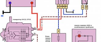
Differences in generators
In any case, the differences in the wiring diagram of the models will primarily depend on the power unit - carburetor or injection.
The main differences in carburetors:
- models 21213 use the generator unit model 371.3701;
- in the engines of models 21214, the manufacturer decided to install a more powerful generator device; it is marked with the numbers 9412.3701 (video author - Sergei Chekhonin).
And although these generators are different, they have certain similarities in design. In any case, it is a synchronous AC device. In addition, these units have a built-in rectifier and output voltage regulation mechanism.
Wiring differences
If we talk directly about wiring, then depending on the car model, it may also have differences. It should be noted that these differences greatly simplify do-it-yourself maintenance and repair of the system. As for injection modifications of SUVs specifically, in this case the system is equipped with three outputs intended for installing electronic ignition.
In addition, 21214 cars use two ventilating devices that perform the function of cooling the radiator assembly. Accordingly, due to the use of additional fans, the wiring also underwent, albeit not significant, differences. Of course, they are not fundamental.
Fuses used in the electrical circuit of the Niva 2121 car
Fuses are used to protect almost all electrical circuits in the system.
In the event of a short circuit, they instantly burn out and open the connection, turning off the protected equipment.
The use of fuses on the Niva 2121 car has a number of its own features:
- All electric motors of the gearmotors that control the windshield wipers are reliably protected by fusible inserts that can be reused. They are of the bimetallic type and operate fully automatically;
- to minimize the risk of a short circuit in the equipment circuit, fuses with a wire with a cross-section of 1 mm are used to supply power to the fuel injection system. Such inserts burn out instantly, opening the network and completely eliminating spontaneous combustion;
- circuits of equipment such as a battery, ignition and engine starting systems, and a generator do not need protection, so fuses are not integrated into them at all;
- the power supply system to the electric cooling radiator fan is protected by an insert that can withstand current and more amperes;
- the electric fuel pump, optical equipment, electric fan motor and other high-power consumers are connected to the on-board network through a special relay equipped with its own fuse and do not require any additional protection;
- 15 amp fuses are installed to protect the electrical circuits of the electronic control unit, fuel pump and main relay of the fuel injection system.
Designations of fuses and their purpose
To protect electrical circuits on cars, fuses are used, located in a special mounting block. On a Chevrolet Niva VAZ 2123, this block is located inside the instrument panel, to the left of the plastic steering column cover.
The placement of blocks in the cabin is the same for cars of all years of manufacture.
The main blocks of machines are divided into two types - before 2009 and after. These devices are not interchangeable. The blocks behind the glove box are identical in design.
On a 2005 car, you can easily install a block from a 2011 car. The designation of the fuse rating is marked on the body; on the assembly itself there is a number of the fuse link and a pictogram of the purpose.
There are no fuse markings on the main unit cover.
A typical fuel pump relay 75.3777-10 has 4 contacts, a coil with an armature, and a spring for opening the contact. When voltage is applied to the control contacts, the rod is drawn into the winding and another pair of contacts is closed. It turns off automatically as soon as the low-current connectors are de-energized.
Advantages of using relays in Niva Chevrolet cars:
- spontaneous leakage current in the on-board system is eliminated;
- reliable control of all electric motors;
- quick and guaranteed start of electrical mechanisms;
- Network overload protection.
Fuse location
All fusible links used in the electrical circuit of the Niva 2121 car are divided into two groups.
They are located in the fuse boxes located under the dashboard to the right of the driver's seat. You can easily find a description of each of these safety devices, as well as their technical characteristics, in your vehicle's owner's manual. If any electrical equipment in your car has failed, the first thing you need to do is check that the fuse is working properly. To do this, it is very important to follow the following safety rules:
- Before replacing the fuse link, it is necessary to identify and eliminate the cause of its failure;
- In no case should you install fuses that do not meet the requirements of the car manufacturer;
- It is strictly forbidden to close the contacts of the inserts with any metal objects;
- Do not remove fuses from the block using a screwdriver or knife without first turning off the power supply.
In the figure below you can see a detailed diagram of the location of the fuses of the Niva 2121 car, as well as the connections of all electrical equipment.
Features of electrical equipment
The standard wiring on the VAZ 21213 differed from the circuit used on the VAZ 2121. In particular:
- The fuse box on the VAZ 21213 uses more modern “knife” fuses, for which the contact pad is modified;
- The power system uses EPHH - forced idle economizer, for which there is a separate harness with a block in the engine compartment wiring;
- The ignition system uses a non-contact circuit built on a microcontroller.
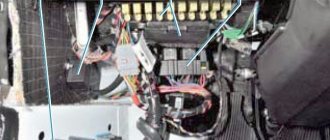
Differences in the engine compartment
The EPHH control unit is located in the engine compartment and is a plastic box with a connector for connecting a wiring harness to it. Its purpose is to ensure stable engine operation when coasting, including fuel economy.
Self-diagnosis capability
To make it easier to determine engine failure, car owners use a search algorithm based on the car manufacturer’s recommendations.
The manufacturer recommends using it first, and only then resorting to the help of another car:
- Use of known good parts;
- Easy start (“lighting up”), etc.
Conclusions: self-service of a car has long become the norm for our car owners. Moreover, video manuals with explanations of the work have become more accessible today, allowing you to avoid mistakes when troubleshooting the electrical network.
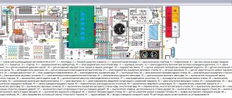
SCHEME VAZ-2121
SCHEME VAZ-2121
VAZ 2121 “Niva”, developed and produced since 1979.
Electrical diagram of VAZ-2121:
1. Headlights, 2. Headlights, 3. Headlight cleaner motor, 4. Horn, 5. Headlight washer motor, 6. Windshield washer motor, 7. Generator, 8. Side turn signal, 9. VAZ-2121 battery, 10. Heater motor, 11. Additional resistor for heater motor, 12. Windshield wiper relay-breaker, 13. Starter, 14. Windshield wiper motor, 15. Carburetor limit switch, 16. Carburetor solenoid valve, 17. EPHH control unit , 18. Switch, 19. Spark plugs, 20. Distributor (ignition distributor, 21. Oil pressure sensor, 22. Temperature sensor, 23. Carrying socket, 24. Ignition coil, 25. Brake fluid level sensor, 26. Relay for turning on wipers and headlight washer, 27. Rear window heating relay, 28. High beam relay, 29. Low beam relay, 30. Ignition relay, 31. Starter relay, 32. Differential lock lamp switch, 33. Exterior lighting switch , 34. Cigarette lighter VAZ-2121, 35. Brake light switch, 36. Reverse light switch, 37. Turn signal and car alarm relay breaker, 38. Main fuse block, 39. Additional fuse block, 40. Backlight lamp heater levers, 41. Rear fog lamp switch, 42. Rear window heating switch, 43. Heater motor switch, 44. Rear window wiper and washer switch, 45. Hazard warning switch, 46. Ignition switch, 47. Air control lamp carburetor flap, 48. Instrument lighting control, 49. Steering column lever switch, 50. Carburetor flap warning lamp switch, 51. Rear window washer motor, 52. Door lamp switch, 53. Interior lamps, 54. VAZ-2121 instrument cluster, 55. License plate lights.
Why was this diagram useful to you?
The VAZ injection system fuses are located in a separate block on the left side panel under the instrument panel. As for the versions, here we also had to use a more powerful generator.
Good luck on the roads! Connection diagram of a VAZ engine management system with distributed fuel injection under Euro-2 toxicity standards with an MP 7 controller.
Additionally, the power system uses a forced idle speed saving device.
Do you use Niva electrical circuit diagrams? Poll I can decipher the circuit diagram for any car. Only the circuit diagram for my own car. I can’t.
Below is a diagram of a VAZ external lighting lamp switch. Portable lamp socket.
Yes, all the time. VEHICLE ELECTRICAL EQUIPMENT.
Ignition system
The operation of the internal combustion engine installed on the VAZ 2121 car is based on a classic scheme, a video of which is shown in driving courses:
- The generator produces electric current;
- The ignition coil increases its power;
- The ignition distributor supplies electrical impulses to the spark plugs when the piston reaches TDC;
- The spark plugs ignite the air-fuel mixture in the engine cylinders.
The photo shows the following components:
- From pos. 3 to 12 – ignition coil and its structure;
- From pos. 13 to 20 – spark plug;
- From pos. 21 to 42 – ignition distributor (distributor).
For reference: The distributor slider, which is responsible for closing the contacts with the high-voltage wires going to the spark plugs of each cylinder, is shown separately. In the diagram presented, it is indicated by pos. 41-45.
Engine modernization
The all-wheel drive transmission of the VAZ 2121, in addition to significant advantages, also had domestic disadvantages. In particular:
- Fuel consumption was quite high compared to passenger cars (13.4 liters per 100 km in urban conditions and off-road);
- This was reflected in operating costs - the price of 1 km was much more expensive for the owners. And the power of the existing engine was insufficient for harsh off-road conditions.
For reference: the automaker, by modernizing the existing engine, increased its technical parameters. In particular, the volume increased from 1480 cubic meters. cm up to 1680 cc see Cars with such a power unit received the factory index VAZ 21214.
An increase in engine displacement and the use of a non-contact ignition system led to the need to modernize the electrical circuit in the engine compartment. Replacing the VAZ 2121 wiring solved this problem completely.
Ignition system modernization
Since the high-voltage coil is traditionally responsible for the sparking power, the automaker has made changes to its operation. In particular, the wiring on the VAZ 2121 was supplemented with a harness that connected the switch and other components of the ignition system.
This factory manual contains:
- Ignition switch acting as an electrical circuit switch with pins 30/1 and 15;
- Ignition relay with pins 85,86,30 and 87;
- Switch with 6-pin terminal block;
- Upgraded ignition coil with terminals “B” and “K”;
- Distributor (ignition distributor);
- Candles.
Lada 4×4 3D 2121 › Logbook › Electric fans 21214 in 2121
Just a short note about the installation. Inspired by an article on Niva-Fak and tired of constant boiling, I broke my piggy bank and went to the local car market, where I purchased: 1. Electric valves 21214 2. Tee for a sensor from a GAZelle 3. Sensor TM-108 87-92 degrees 4. Relay 711.3747-01 5. Fuse 30A 6. VAZ-2101 heater control button 7. Rubber radiator pads from VAZ-2108 2 pcs. So, part one is installation. In the article at the link, the guy writes that he barely inserted the valves into the face, raised the steering wheel, tightened it, sawed it off and installed it - DON’T DO THIS!
The valves rest with their lower legs against the holes in the muzzle, and with the upper rubber bands they press the radius against the top of the muzzle, and that’s it. Nothing warps or rubs, everything works PERFECTLY. And the sides on the upper elastic bands hint to me personally that this is how it should be, there is no need to cram in what cannot be squeezed in. At the same time, they unscrewed the native Carlson so that it would not take away the power from the already shaky Pihl. Also in the process, the gene belt was replaced, because it was slightly worn. The threesome with the sensor was cut into the lower pipe, it didn’t go in without a curse, but it went in.
The photo is not so great, but the car looks clearly better
Part two - connection. The diagram in the article, unlike the instructions, is more clear. Everything was connected according to it, only the wires on the button were swapped: ground with any other.
Result: the scheme works, but they hum - mother, don’t worry. for some reason you immediately feel like you’re on a Junkers
The sensor turned out to be too hot - according to the display meter, it turns on when the needle has already crept well over 90. The voltage at 2000 rpm with the valves on drops to 13 volts
Dashboard
For subsequent modifications of the VAZ 2121, the instrument panel was thoroughly redesigned. In particular, the design and location of the warning lamps have changed, and new scales have appeared on the instrument panel indicators.
Conclusions: the owners of the VAZ 2121 car often serviced it themselves. And servicing electrical systems is impossible without original circuit diagrams. This was especially true for modernized versions, where changes were made to the operation scheme of components and assemblies.
Electrical wiring of VAZ 21213: differences in the engine compartment and the possibility of self-diagnosis
Like any other domestic car, the VAZ 21213 is in most cases serviced by the hands of its owner. This is the specificity and even the mentality of our car enthusiasts, who, in addition to tools, also require a technical description of the main components and assemblies.
And the detailed wiring diagram of the Niva VAZ 21213 is just one of them, since in harsh operating conditions it is often necessary to restore the car in field conditions, because:
- VAZ 21213 is an off-road vehicle;
- Used by owners away from service stations and workshops;
- The life and safety of people (the owner and his family members) living far from large cities often depends on its technical condition.
Schemes on Niva with injection engine
The fundamental difference between a carburetor electrical circuit and an injection circuit is the use of an improved power unit control system.
Diagram of the engine control system of the injection Niva
Let's look at the interactive diagram of the EMS injector with 8 valves:
- Adsorber purge device.
- Throttle mechanism.
- A controller that determines the temperature regime of the engine; its readings are based on the temperature of the coolant in the cooling system.
- Radiator ventilator located to the right of the engine.
- The same fan, only installed to the left of the power unit.
- The ignition system coil is located in the engine compartment.
- Spark plugs with connected high-voltage wires.
- Air flow controller supplied to form the combustible mixture.
- Crankshaft position controller. If it fails, the engine will not start.
- Wiring harness connected to the oxygen concentration controller.
- Oxygen control controller.
- Camshaft timing regulator or camshaft sensor.
- Knock controller. Affects idle speed.
- Harness connected to the injector connection wiring.
- Directly the system injectors themselves.
- Designation of the gas pedal located in the cabin.
- A harness with wiring connected to the control panel.
- Main relay.
- Protective element of the right ventilation device.
- A similar component protects the left fan circuit.
- A relay that ensures the operating condition of the fuel pump circuit. If it breaks, the pumping device will not be able to operate, making it impossible to start the engine.
- Safety element responsible for the pump.
- Connector to which the fuel pump in the module is connected.
- Diagnostic connector is used to troubleshoot various vehicle systems.
- Plug connecting electrical wiring to ground.
- Mounting block with safety elements that ensure the operating condition of the power unit control system.
- The connector to which the electrical wiring of the APS operating status indicator lamp is connected.
- Connector with connected wiring of the communication coil of the same system.
- The control module of the car alarm, with its help the anti-theft device is configured.
- A connector with a connected wiring block coming from the diagnostic oxygen concentration controller.
- Diagnostic controller.
- Central motor control module. These car models use Bosch 17.9.7 ECUs.
There is also a symbol A in the diagram - in this place the wiring harness passes from the engine compartment into the car interior.
What do the numbers in the Niva index mean?
The only thing the owners complained about was the car’s insufficient power, which did not allow it to realize its full road potential. There were objective technical difficulties associated with a shortage of production capacity, which the automaker managed to overcome over time.
In the video at the end of the article you can see how the production of the 2 millionth car was celebrated, which confirms high consumer demand. In a word, the developers did not remain deaf to modern trends, proposing several modifications of power units for the VAZ 2121 Niva.
| Engine capacity | Injection system | Ignition system | Power, hp | Factory index |
| 1.6 l | carburetor | classical | 79 | VAZ-21210 |
| 1.7 l | carburetor | classical | 80 | VAZ 21213-1000260 |
| 1.8 l | carburetor 21073 Solex type or injector | contactless/injection - electronic with Bosch MP 7.0 controller | 82/85 | VAZ 2130-00 – carburetor VAZ 2130-20(26) – injection |
| 1.7 l | distributed fuel injection | contactless with BOSCH MP 7.9.7 controller. or JANUARY 7.2 | 83 | VAZ-21214-20 |
| 1.9 l | diesel XUD-9SD | — | — | VAZ-21215 |
To determine the engine type, you should look at its code on the block
Accordingly, the cars themselves received new indices linked to the installed power unit:
- A 1.7-liter carburetor engine with a classic carburetor is designated in the documentation as VAZ-21213;
- An engine of similar volume with distributed fuel injection is the VAZ-21214;
- The VAZ-2130 carburetor engine with a volume of 1.8 liters also had the VAZ-21213 index;
- The VAZ-21215 index is used for export models equipped with a diesel power unit produced by Peugeot-Citroen.
The photo below shows the wiring diagram of a VAZ 21213 with a classic carburetor power unit.
Diagram of a VAZ 21213 with a 1.7 liter carburetor engine
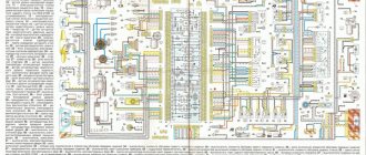
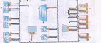
Electrical diagram of VAZ 21214 with distributed fuel injection
A - rear wiring harness wire connected to switch 4; B - wires connected to plug “1” of fuse block 24 (one wire goes to plug “15” of the ignition switch, and the other to plug “85” of the ignition relay); B - rear wiring harness wires connected to the fuel level indicator.
The order of conditional numbering of plugs in blocks:
a - controller; b — control unit of the automobile anti-theft system; c — air flow sensor; g — speed sensor; d — indicator of the state of the automobile anti-theft system; e — electric fuel pump and oxygen concentration sensor; g - throttle pipe; h — ignition module.
* Gray wires in block 25 are the vehicle speed signal output, the yellow-red wire is the fuel consumption signal output (for the trip computer).
As soon as we bought the car, one of the main points of improvement was the electrics. There are a lot of wires in the engine compartment that don't go anywhere. The condition of other wires and terminals is not clear... When they dismantled the interior, they threw out a full bucket of wires. Apparently one of the owners was a distinguished music lover)) It’s a pity there are no photos left of this bucket.
We change everything! On the Niva-lada4x4 website we ordered the NIVA 21213-3724030 wiring harness; 21213-3724010; 21213-3724210 (panel, interior, engine compartment).
I didn’t work with electrics, so I had to delve into everything and figure it out. The VAZ 21213 electrical diagram helped with everything.
For convenience, I decided to take everything. I started small, with the ignition control harness.
Then another tourniquet, from the engine compartment. Headlights, turns, gene, starter, fluid and temperature sensors.
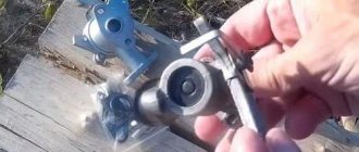
Generator replacement
To repair or replace the generator, the car owner will have to remove the unit completely from the car or turn to professionals for work. If you still want to carry out the replacement yourself, then first you will need to prepare all the necessary tools:
- hammer;
- extension;
- keys to "10" and "19".
The procedure consists of the following sequence of actions:
- First, you will need to park the car in a place designated for inspection and repair. The car will also need to be secured using special wheel chocks. Finally, in order for the work to be carried out safely, you should disconnect the battery by disconnecting the terminals from it.
- After this, you need to remove the engine protection. It is attached to several bolts, and they must be unscrewed to get to the lowest bolt of the generator.
- After this, you will need to knock out the mounting bolt using a hammer. It is recommended to knock carefully so as not to damage the thread and to prevent the bolt from coming out in the opposite direction. A hammer is necessary, since a wrench or any other tool simply cannot handle a bolt.
- Next, you need to remove the bolt, swinging the generator from side to side. It is necessary to bolt in any case, as this makes it easier to remove the rod.
- The fourth step involves disconnecting the wiring. To do this, the power wires connected to the housing are disconnected from the unit. In this case, you can first disconnect the plug from the wires.
- Wires are also attached to the generator, tightened with a nut or bracket. In this case, the nuts must be unscrewed with a wrench, and then the loose wires must be pulled out.
- Finally, after disconnecting the wires, you can begin to unscrew the upper fastening element with the belt tensioner. For this you will also need a wrench, as well as a small extension cord.
- Disconnecting the fastener will allow you to remove the belt and alternator. Then you can start cleaning the vacated space with a brush and installing a new unit.
The structure is assembled in the reverse order; the entire procedure will take about two hours if you have all the necessary tools.
We recommend: Detailed instructions for qualified replacement of the Chery Fora timing belt
Additionally, it is worth noting that when everything is assembled, you will need to adjust the position of the generator using the tensioner. To do this, you need to unscrew the tensioner nut and tighten or loosen the belt, while observing the battery charge.
If the indicator returns to normal, then the selected tension is sufficient. There is no need to tighten the structure, as the generator bearing may fail. If the tension is insufficient, the generator will work intermittently, and this can also lead to breakdown.
Features of replacing the ignition switch
First of all, it is important to make sure that the problem is in the lock. Therefore, the spark plugs, distributor and ignition coil are inspected.
Often these parts of the internal combustion engine become the reason for failures of correct operation. If breakdowns in them are excluded, then the ignition switch (IZ) should be replaced. Removal order:
- Disconnect battery.
- Remove the steering column.
- Mark the wires going to the 3Z contact area. Using a flat-head screwdriver, unscrew the bolts securing the switch to the steering column (left and right).
- Insert the key into position 0. By pressing the screwdriver, press the lock slightly through the hole (do not touch the key).
- Lightly pull the 3Z towards you and dismantle it. The ignition switch Niva 21213 is switched off according to the wiring diagram (the contact part is changed if required). To do this, be sure to remove the retaining ring with a screwdriver.
- Remove the key, install the contact part so that the wide protrusions of the body and the parts coincide.
- The remaining parts are assembled in the reverse order.