Lada Vesta, like all modern cars, has a large amount of electronics and electrical equipment. In order for this whole thing to work and function properly, the car requires electrical wiring, which, like the veins in the human body, literally permeates the entire body of the car. If we pull out all the wiring of the Lada Vesta and measure its length, we will get a figure of several hundred meters.
The need to study electrical circuits most often arises when an element breaks down or fails. In this case, it is necessary to correctly diagnose and establish the cause of the breakdown - to “sentence” the element itself or the wiring to replacement. Let's look at a small example. The car lost idle speed. The diagnostics revealed an error in the XX regulator. There may be several reasons - either the regulator itself has failed, or poor contact on the wire chips, or a break in the wiring. Before buying a regulator, you need to make sure that the problem is not a broken electrical circuit. We can do this with a tester and test the wiring. But here's the problem. The IAC wires are located under the hood, and control comes from the ECU in the cabin. So what should we do? In this case, the Lada Vesta electrical diagram will help us. Using the diagram, we can find where the contact is coming from the ECU to the IAC and make a call without any problems. This is a seemingly very simple situation, but without knowledge of the Lada Vesta electrical circuit it would not be possible to solve it in a short time.
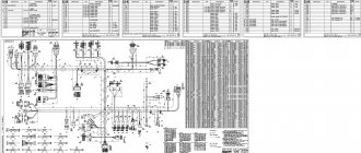
In this article you will find all the electrical equipment diagrams of the Lada Vesta with a detailed description. So, let's go.
Connection diagram for rear auxiliary wiring harness
Front left door wiring harness connection diagram
Lada Vesta: Electrical equipment pinout
Modern AvtoVAZ cars are already at the level of imported competitors in terms of the availability of standard equipment and installed auxiliary devices.
The Lada Vesta itself differs from outdated models in the abundance of electronics and increased reliability of the chassis. On the other hand, car enthusiasts often complain about frequent failures of electrical equipment and their weakness when used in domestic conditions.
Consequently, the Vesta pinout is in great demand among specialists or ordinary drivers.
How to increase the service life of electrical equipment
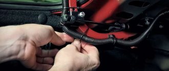
To extend the life of standard wiring, it is recommended to perform certain actions. Periodically check the tightness of the plugs - during active driving, the plastic fasteners may wobble, which can cause a short circuit.
Before active use, treat all detachable connections with special oil. This will prevent their oxidation and deterioration of impulse transmission.
Every year check the condition of the wire braiding - during operation there are strong temperature changes on the main line - this dries out the insulation and stimulates short circuits.
Pinout of Lada Vesta: decoding of contact groups and equipment terminals
A complete set of car wiring is difficult to understand due to the abundance of connections and individual elements. For easier decoding, the wiring of the on-board equipment is presented below in individual parts.
Pinout of the front electrical harness
The front part of the wiring is 80% concentrated in the engine compartment and is responsible for the normal operation of the engine and the mechanisms that serve it. The following is the wiring sequence:
- 1/7 – contact group of the right and left headlights;
- 2/5 – “dads” of head optics foglights;
- 3 – alarm horn;
- 4 – standard electric fan serving the main engine radiator;
- 6 – audible warning signal;
- 8 – standard air conditioner pressure sensor;
- 9 – connection of the control unit for the central radiator head fan;
- 10 – junction of ECU transmission wiring;
- 11 – standard sensor that measures the air temperature outside the car;
- 12/13 – ABS system sensors that read the rotation speed of the front left and right wheels, respectively;
- 14 – ECU;
- 15 – engine compartment lid lock position controller;
- 16 – power supply to the electric drive of the windshield wiper;
- 17 – windshield washer motor;
- 18 – electrical part of the adsorber purge valve;
- 19 – main ABS module;
- 20 – output to block No. 3 of the standard terminal of the instrument panel;
- 21 – standard brake line expansion tank meter sensor;
- 22 – blocks for the mounting block of fuses and protective relays;
- 23 – output to block No. 2 of the instrument panel;
- 24 – standard power output of the heating element for the aft windshield;
- 25 – output to the first connector of the instrument cluster;
- 26 – terminal output for connecting the ECM unit.
Pinout of Lada Vesta, section responsible for starting the power plant
A small part of the wiring is responsible for the main elements of equipment designed to start the power plant:
- 1 – generator block;
- 2 – standard fuse module;
- 3 – connection of the power supply element for on-board circuits;
- 4 – electrical part of the starter;
- 5 – sending a signal to the wiring of the front harness.
Vesta devices pinout combinations
All groups of contacts coming from on-board systems and sensors are concentrated in this part. The area is responsible for indicating the vehicle's status in real time.
- 1-3/9 – output to the disconnect terminal of the front equipment harness;
- 4 – on the aft wire bundle;
- 5/19 – device of the steering column switch – left side;
- 6 – electrical socket, protective element;
- 7 – standard steering wheel rotation degree sensor;
- 8/14 – protective insert for the door window lift device;
- 10 – standard key for headlight adjustment;
- 11 – insert for protecting the main fuel pump;
- 12 – similar insert responsible for the heater fans;
- 13 – relay for the device of external lighting units of the car;
- 15 – standard PPS sensor;
- 16 – button for switching operating modes of the cargo compartment lock;
- 17 – diagnostic block, designed to connect the external scanner;
- 18 – arrangement of a combination of fusible protective inserts inside the passenger compartment;
- 20 – driver airbag output;
- 21 – standard control key module located on the steering wheel;
- 22 – contact group of the airbag ring;
- 23 – ignition lock cylinder;
- 24 – antenna of the standard immobilizer system;
- 25 – pins for connecting accelerator pedal contacts;
- 26 – stop signal button is turned off;
- 27 – electric power steering device;
- 28 – contact group of the heating system fan;
- 29 – dashboard;
- 30 – cigarette lighter;
- 31 – on-board audio player;
- 32 – emergency warning button;
- 33 – dashboard push-button switches;
- 34 – module for monitoring and starting the interior heating device;
- 35 – standard front passenger airbag;
- 36 – glove box illumination lamp;
- 37 – control device for the GLONASS satellite navigation system;
- 38 – secondary heater operation control module;
- 39 – airbag activation device switch;
- 40 – button for turning on the glove compartment lamp;
- 41 – central module for monitoring the electrical equipment of the cabin;
- 42 – antenna for standard satellite navigation of the GLONASS system;
- 43 – audio system receiver;
- 44 – signal and power supply output to the aft part of the right auxiliary instrument cluster;
- 45 – a similar waterproof output to the second connector of the above element.
Pinout of the rear additional wire bundle
- 1 – parking sensor control system;
- 2 – contact group for connecting the rear bumper lines;
- 3-4 – output to the central bundle of wires;
- 5 – electric drive for the cargo compartment lid lock;
- 6-7 – license plate lighting lamps;
- 8 – lamp designed to illuminate the interior space of the luggage compartment;
- 9 – auxiliary stop signal;
- 10 – directly the servo drive of the trunk lid lock;
- 11/12 – left side of the stern lights;
- 13 – heating of the wind window of the rear part of the vehicle;
- 14/15 – right side of the illumination of the rear optics module.
Pinout of the rear on-board wiring block
Here is the equipment located in the rear of the vehicle:
- 1 – terminal connector designed for connection with the left front door;
- 2/7 – ABS system sensor, responsible for the rear right/left wheel;
- 3/6 – door position switches;
- 4/5 – fuel pump control unit;
- 8/9 – connector to block No. 2/1 of the rear auxiliary harness;
- 10/11 – outputs for connecting to the dashboard;
- 12 – control unit for car body panel equipment;
- 13 – cabin module for measuring internal temperature;
- 14 – plug block on the driver’s door;
- 15 – precipitation warning module;
- 16 – device for lighting the interior of the car.
Rear bumper wiring diagram
A separate part of the power cables designed to supply power to equipment located in the aft bumper:
- 1/2/4/5 – parking sensors;
- 3 – stern fog lights;
- 6 – connection device to the rear auxiliary wiring bundle.
ECM wiring connection
- 1 – reverse signal lamp switch;
- 2 – standard DPKV;
- 3 – electric clutch of the air conditioning compressor;
- 4 – electronic engine control unit;
- 5 – DCC;
- 6 – electric throttle drive;
- 7 – DTOZH;
- 8 – diagnostic oxygen concentration sensor;
- 9 – sensor measuring absolute pressure in the intake manifold;
- 10 – output of a control device indicating a critical drop in pressure inside the crankcase compartment of the engine;
- 11 – electromagnetic insert for controlling the intake position;
- 12 – plug output to the front wiring harness;
- 13 – electric generator;
- 14 – detonation channel length sensor;
- 15/18 – blocks for connecting the ECM unit to the injectors, sequentially for each drive;
- 16 – phase distribution sensor;
- 17 – to the ignition coils;
- 19-22 – ignition elements;
- 23-26 – injector drivers;
- 27 – standard capacitor.
Driver's door pinout
- 1 – electrical part of the door lock servomotor;
- 2 – threshold illuminator lamp;
- 3 – electric window motor-reducer;
- 4 – device for connecting fuse links;
- 5 – drive for controlling the position of the rear view mirror;
- 6/7 – areas for connecting high-frequency/broadband speakers;
- 8 – output to the rear wiring harness.
Important! The pinout is also relevant for the passenger door.
Connecting the manual transmission electronics unit
There are only five nodes, each of which is responsible for its own part of the mechanism:
- clutch module actuator;
- gear selection device;
- sensor measuring the speed of the drive shaft;
- gear shift mechanism;
- exit to the EBKP connection.
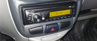
Vesta radio pinout
The standard connection block for the radio has 12 pins corresponding to individual elements. Moreover, each wire is painted in its own color for identification.
The pinout of the standard Lada Vesta radio is relevant for devices of most modern analogues. Consequently, there are no problems when replacing it, which guarantees a large selection of third-party models for modifying the machine.
CAN bus pinout
There are several outputs here and each of them is responsible for its own section of the diagnostic device:
- 2 – positive terminal;
- 4 – grounding of body panels;
- 5 – signal ground wire;
- 6 – J2284;
- 7 – K-line diagnostics;
- 10 – tire 1850;
- 14 – CAN-LOW 2284;
- 15 – diagnostic line L;
- 16 – voltage supply from the car battery.
How to avoid connection problems
When repairing or replacing electrical units, some users make mistakes by connecting the wrong terminals, which causes short circuits and burnout of parts. To avoid possible problems, experts recommend studying the location of pins and contact groups in advance, and also marking the contacts yourself before disconnecting them.
Bottom line
The above Lada Vesta pinout is taken from the manufacturer's service documentation supplied with the new car. At the same time, general provisions are indicated - depending on the configuration and year of manufacture, the connection of outputs and the location of units may differ slightly.
If you are unsure of your own abilities, it is recommended not to interfere with the car yourself, but to contact a qualified technician.
Purpose and description
The central body electronics unit (CBEC) came from Renault and is located under the panel behind the glove box. The block is designed to perform the following functions:
- Access control system functions;
- Starter control;
- Control of relays of additional consumers;
- Control of the rear window heater and electric side mirror heaters;
- Windshield defroster control;
- Control of direction indicator and hazard warning lamps;
- Interior lighting control;
- Control of door sill lamps (for the “Lux” package);
- Trunk lighting control;
- Windshield wiper control (for “Classic” and “Comfort” trim levels);
- Energy saving control of vehicle interior lighting devices;
- Monitoring the state of the brake signal switch (BST);
- Monitoring the state of the clutch pedal position signal switch (CPPS) (for configurations with a manual transmission);
- Indication.
Fuse box Diagram and location of Lada Vesta (Lada Vesta)
In any car, sooner or later, the car owner is faced with the inoperability of certain components and assemblies, especially when it comes to electrics. The cigarette lighter may stop working, the lights may go out, the air conditioning may turn off, or the interior lighting may simply fail. Lada Vesta was no exception.
Before replacing a faulty unit, you must check the fuses that protect these circuits. Or a relay. All this is traditionally located in the fuse box, of which the Lada Vesta has two - one in the cabin and the second in the engine compartment.
Let's look together at which fuses and relays are responsible for what and where exactly to go if certain electrical appliances fail in Vesta. Let's start with the interior fuse box.
- Location of the interior fuse box of the Lada Vesta:
- In order to gain access to the fuse box in the Lada Vesta, we need to remove two latches, this is done as follows:
- Congratulations, if you did it carefully, the rivets will remain intact, they are reusable
- This is what the fuse box looks like in a Lada Vesta
- Let's look at the schematic designation of relays and fuses in the cabin unit on Vesta:
- Now let’s find out which electrical circuits are protected by fuses in the block:
- Warning
- The presence of fuses depends on the degree of electrical equipment of the vehicle.
- Interior mounting block relay
On-board computer control algorithm
1. Selection of on-board computer functions (carried out using the keys on the right steering column switch).
2. Selecting trip meters and switching between clock and temperature.
3. Enter parameter setting mode, select parameter.
3.1. Setting the time.
When you exit the time setting mode, the seconds counter is reset to zero (reset without rounding). If there are no button presses within 60 seconds, the time setting mode will exit automatically.
4. Display mode of parameters of the “Cruise control” or “Speed limiter” functions.
In the mode of displaying the parameters of the “Cruise control” or “Speed limiter” functions, it is possible to switch the displayed function of the on-board computer (point 1) and the total and daily mileage counters (point 2), the indication of outside air temperature and time is not available, parameter setting modes (point 3 ) are not available.
- “short” – press for less than 1.5 seconds, triggered when released.
- “long” – press for more than 1.5 seconds, triggered by time.
- yellow color – the segment is blinking (square wave, 1 Hz).
- When resetting the route parameters (clause 3(d)), the following parameters are reset to zero: average fuel consumption, fuel consumed, travel time, average speed.
Bookmaker settings are also shown in the video:
To change the sound of the turn signals, you need to go to the secret menu (it does not work on the instrument cluster). To do this, press two BC buttons at the same time. More detailed instructions in the video:
Are you satisfied with the functions of the Lada Vesta on-board computer? Let us remind you that other operating instructions for this vehicle can be found in this section.
It is difficult to imagine a modern car without an on-board computer (alternative names: “BC”, “carputer”, “onborder”), which allows you to increase engine efficiency, reduce gasoline consumption, optimize the operation of the gas distribution system and synchronize the interaction of all units. In addition to the above, BC reduces the concentration of harmful emissions. The onborder performs the functions of cruise control, climate control, and displays the information necessary for the driver, allowing him to make the right decisions on transport management and optimal movement along the chosen route. That is why all modern Lada Vesta models are equipped with BCs that successfully perform the functions assigned to them.
How to avoid connection problems
When repairing or replacing electrical units, some users make mistakes by connecting the wrong terminals, which causes short circuits and burnout of parts. To avoid possible problems, experts recommend studying the location of pins and contact groups in advance, and also marking the contacts yourself before disconnecting them.
The above Lada Vesta pinout is taken from the manufacturer's service documentation supplied with the new car. At the same time, general provisions are indicated - depending on the configuration and year of manufacture, the connection of outputs and the location of units may differ slightly.
If you are unsure of your own abilities, it is recommended not to interfere with the car yourself, but to contact a qualified technician.
