05/08/2020 480 Electrical wiring and electrical circuits
Author:Ivan
The ability to read and understand the electrical diagram of a VAZ 2115 allows you to determine the cause of a malfunction that occurred on the road, as well as independently install additional equipment. It should be taken into account that cars of different years of production differed in the electrical system and instruments.
[Hide]
What's new in the wiring of the VAZ 2115
The early VAZ 2115 passenger car has wiring similar to the VAZ 21099 circuit, but later additional elements appeared. The new sedan is, in fact, the result of a deep modernization of the previous generation car. The design uses modernized head lighting equipment and an electronic instrument cluster. Because of this, modified plugs appeared in the wiring, and some of the wires began to have an increased cross-section. The length and route of laying have also been changed.
The cars use an electronic immobilizer. The device is connected to the units via separate wiring and has its own control controller. Injection engines were equipped with a catalytic converter for exhaust gases. Some cars received lambda probes installed before and after the device.
In 2011, cars began to be equipped with an electronic gas pedal, which reduced exhaust emissions. In addition, the range of options offered by the plant has expanded. These elements influence the electrical circuit of the VAZ 2115.
Modifications of VAZ 2115
All serial modifications of the VAZ 2115 were equipped with an in-line 4-cylinder 8-valve engine with a displacement of 1.5 and 1.6 liters:
- early version 2115 with a carburetor 76-horsepower engine 21083, produced from 1997 to 2000;
- the slightly modernized 2115-01, equipped with a 68-horsepower version of the 21083 engine with a carburetor, was built in small batches in 1998-2000;
- version 2115-20, equipped with a 2111 engine with mixture injection, power 78 hp. pp., cars were produced in 2000-2012;
- Since 2003, model 2115-40 began to roll off the assembly line, equipped with a 1.6-liter unit that developed 80 hp. With.;
- in 2007, the final modification 21154 appeared, equipped with an 81-horsepower VAZ 11183 engine.
The Tolyatti plant assembled the last cars in 2012. These included small-scale 2115-91, equipped with a Wankel rotary piston engine. The unit had a working volume of 1.3 liters and produced up to 135 liters. With.
Other malfunctions
There are other types of breakdowns that can occur with the starting system of the VAZ-2114 power plant, and each of them has its own symptoms:
- If the starter turns even after it has been switched off, the most common culprit is that the relay armature is stuck in the retracted position. In this case, you can stop the starter only by disconnecting the battery from the on-board network (by removing one of the terminals). Everything can be eliminated by rebuilding the relay or replacing it;
- If the starter turns on without permission, it is likely that the relay cover is damaged. As a result, the armature spring, which holds it in the depressed position, loses its support and the armature itself can move without permission inside the relay, periodically closing the contacts. By replacing the retractor, this malfunction can be eliminated;
- The starter starts working, but the flywheel does not spin, and a cracking sound is heard. There are two reasons for this malfunction. The first is that the starter mounting bolts have become loose, so the starter has come loose and is warped. As a result, the gear cannot engage, but at the same time it rotates and contacts the flywheel (hence the rattling noise). The second is that the gear teeth have crumbled or worn out, resulting in no engagement. To eliminate this, you should first check the tightness of the bolts; if it is normal, then you need to remove the assembly and inspect the condition of the gear;
- The starter turns on, but the flywheel does not turn, and there are no external sounds. This indicates that the gear is not reaching the flywheel. To understand why this happened, you will also have to remove the starter and carry out an inspection.
Read on the topic: How to check a car starter, useful tips.
As you can see, most often problems arise not with the electric motor itself, but with its additional elements - the relay and bendix.
Malfunctions can also occur due to other elements included in the circuit - a lock, fuses, as well as the condition of the wiring connections. Watch the video why the starter on a VAZ 2114 does not turn.
Car electrical protection
To ensure the protection of the electronic components of the VAZ 2115 Samara, knife-shaped safety inserts are used. The devices are located in a mounting block installed in the air intake duct in the engine compartment. The module is closed on top with a plastic cover secured with two latches.
Location of fuses in block 2114-3722010-60
The purpose of the fuses is given in the table.
| Number on the diagram | Denomination, A | Protected devices |
| P-01 | 10.0 (since 2011 - 20A) |
|
| P-02 | 10,0 |
|
| P-03 | 7.5 (for some cars - 10.0) |
|
| P-04 | 20,0 |
|
| P-05 | 20,0 |
|
| P-06 | 30,0 |
|
| P-07 | 30.0 (since 2011 - 20A) |
|
| P-08 | 7,5 | Fog light on right side (optional) |
| P-09 | 7,5 | Likewise for the left side |
| P-10 | 7,5 |
|
| P-11 | 7,5 | Side lighting in the right lamps, front and rear |
| P-12 | 7,5 | Low beam in the right headlight |
| P-13 | 7,5 | Same for the left side |
| P-14 | 7,5 | High beam thread in the left headlight and control indicator for turning on the mode |
| P-15 | 7,5 | Starboard high beam |
| P-16 | 15,0 |
|
| P-17-20 | reserve | Fuses of any rating can be installed and are used to replace burnt-out inserts |
The location of the elements and the appearance of the switching boxes differ depending on the year of manufacture of the VAZ 2115. There are cars with blocks 2114-3722010-60 and 2114-3722010-18.
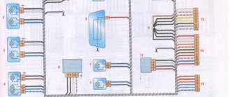
On cars with an injection engine there is an additional unit located in the front passenger's feet. The box is designed for three relays and three fuses (15A), and is covered with a plastic shield on top. The cover is secured with two self-tapping screws.
List of electrical components in the cabin unit:
- fuel pump activation controller;
- main ECM control relay;
- cooling system fan contact group;
- fuse link for the power supply circuit of the electric motor of the gasoline supply pump and injection nozzles (installed on top);
- protection of sensor wiring, cooling system fan and canister purge valve (middle position);
- fuse for the injection and ignition system controller (lowest).
General view of the interior relay block and fuses
Some VAZ 2115 vehicles have additional fuses located directly in the wiring harnesses:
- to protect the fog lamp on the rear of the car (at 8A);
- for safe operation of the standard heating of the front seats (at 16A);
- for powering central locking gearmotors (16A).
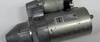
VAZ starter connection diagram
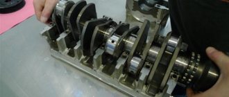
VAZ cars use starters, which are a DC electric motor with an electromagnetic two-winding traction relay and a roller freewheel clutch (overrunning clutch). Starters are used to provide the minimum crankshaft speed required to start the engine. The starter is powered in starting mode from the battery.
The starter relay is connected to the power circuit, thereby closing and opening the circuit, depending on how fast the crankshaft rotates. The starter design on all cars is the same, with only minor design differences. If you understand how the starter works in one car, you can easily figure it out in another.
To prevent a starter failure from taking you by surprise, let’s look at how to replace it yourself. But first, read the theory and study all the options for starter connection diagrams for different models of VAZ cars, collected by the editors of 2 Schemes.ru from familiar auto electricians.
Electrical wiring system maintenance
To ensure the functionality of the electrical system, it is necessary to regularly check and diagnose the components:
- If problems are detected in operation (even minimal malfunctions), the condition of the connecting plugs should be analyzed.
- Often, after the owner moves the pad, contact is restored. Further use of such elements is not recommended.
- The unit needs to be replaced with a similar one, while simultaneously finding out the cause of oxidation of the old parts.
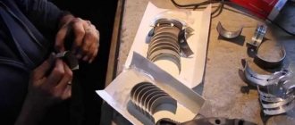
Relay contacts are prone to burning when exposed to high current. The devices can be removed from the unit and the condition of the conductive contacts can be inspected.
This requires:
- Remove the plastic protective cover.
- Carefully clean the burnt contacts with fine sandpaper and blow with air.
If there is significant wear on parts, it is necessary to install new relays.
Due to the location of the installation box in the air supply channel, it becomes clogged with dust and is exposed to moisture. Over time, this leads to the destruction of the conductive paths on the printed circuit boards and loss of contact. The unit should be inspected once a year; if defects are found, it is recommended to replace it with a new one. At the same time, it is necessary to monitor the condition of the grounding wire, which can oxidize at the connection points.
For correct operation of consumers, it is necessary to check the condition of voltage sources. The battery should be periodically recharged from a stationary device. Charging the battery and the functioning of the electrical circuit while driving depends on the tension and condition of the generator rotor drive belt. When the commutator and brushes wear out, the operation of the generator is disrupted, which leads to the car losing power.
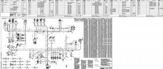
Starter diagram VAZ 2108, 2109, 21099
Electric current enters the starter circuit from terminal “30” of the generator. Next, through block Ш8 (Х8) of the mounting block (pins 5,6), block Ш1 (Х1) - pink wire, to the ignition switch. The driver turns the key in the ignition to turn on the starter (position 2) and closes the contacts (50, 30). After which the ignition switch, through the red wire, current flows to block Ш1 (X1) of the mounting block (pin 8), then block Ш5 (Х5) (pin 4), starter switch relay (pin 85). The relay is activated. From terminal “30” of the start relay, current flows to terminal “50” of the starter traction relay, energizing its winding. The traction relay is activated, activating the starter.
The starter electrical circuit uses a switching relay 111.3747-10.
- Screw securing the protective cap.
- Protective cap.
- Retaining half ring.
- Rear cover fastening nut.
- Back cover.
- Brush springs.
- Brush guides (outer part).
- Brushes.
- Stator.
- Anchor.
- Drive lever.
- Drive unit.
- Restriction ring.
- Retaining ring.
- Drive lever axis.
- Screws for securing the traction relay.
- Front cover.
- Plastic sealing ring for the lid.
- Tie rods.
- Rubber plug.
- Traction relay core.
- Return spring.
- O-ring for traction relay.
- Traction relay.
- Sealing washer.
- Adjusting washers.
Modifications
The VAZ 2115 manufacturer offers consumers a choice of several configurations, on which their cost depends:
- One and a half liter carburetor engine. In this case, the car is marked as VAZ 2115-01.
- An engine with the same volume, characterized by the presence of a distributor fuel injection system. In addition, the car is also equipped with electronic control and is labeled as VAZ 2115-20.
Dimensions of the “fifteenth” Lada
Car electrical equipment
VAZ 2115 injectors or carburetors use a single-wire electrical circuit. In this case, the negative terminal of the power supplies is connected to the minus, and the positive terminal itself is supplied with a separate wire.
As a result of the fact that the VAZ 2115 carburetor and injector have certain differences, there is also a difference in the design features of the wiring:
- In injection versions, the wiring harnesses are slightly larger in size as a result of the fact that the system is equipped with additional regulators and other electrical equipment.
- As a result of the change in the circuit, changes were made to the design of some electrical circuits.
- In addition, the layout of some of the electrical components as a whole was changed.
Wiring diagram on the “fifteenth” Lada
On VAZ 2115 cars, as on its predecessors, the process of repairing the electrical wiring diagram and equipment usually leads to damage to the fixing clips. In any case, if these elements are damaged, they must be replaced, otherwise the electrical wiring may be very close to the hot motor, which will damage it.
Machine electrical protection
The electrical circuit, in particular, the power circuits in these car models are protected from various damages using fuses. The cost of these elements in stores is minimal, but they play a very important role and must always be in working order.
Fuses do not protect only:
- car battery charging diagram;
- ignition circuit;
- electrical circuit for powering the generator and starter.
Electrical equipment is protected by a block in which all fuses are collected, and this block is located in the engine compartment. Electrical equipment such as a starter, windshield wipers, as well as optics are connected to the general circuit via a relay. The relay is also installed in the block. In general, the electrical circuit of the wiper motor and optics is protected by bimetallic reusable elements.
Injector relay block
So, how is electrical equipment protected on domestic cars:
- fuses on the block, which are designed to protect various elements of equipment, are marked as F1-F20;
- K1 is a device that protects the optical cleaner circuit;
- K2 - is responsible for the functionality of the light alarm, as well as turn signals;
- K3 - the element ensures the functionality of the windshield wipers;
- K4 - the device protects the electrical circuit of optics, in particular, incandescent light bulbs;
- K5 - if the car is equipped with electric window regulators, then this relay is responsible for their performance;
- K6 - car steering horn;
- K7 — rear window heating system device;
- K8 - long-range vehicle lighting;
- K9 - low-beam vehicle lighting.
It should be noted that the lamps for the fog lights in the rear headlights are protected separately. For this purpose, a fuse is used, installed in the vehicle interior under the center console. It is located in the wiring harness, next to the optics power button.
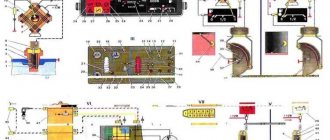
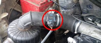
Where is the fan relay located?
4 — electric fan relay; 5 - electric fuel pump relay; 6 - main relay (ignition relay).
Attention: the order of relays and fuses can be arbitrary, we focus on the color of the wires. We then find the relay, which has a thin pink wire with a black stripe from the main relay (pin 85*) (not to be confused with the thin red wire with a black stripe coming from the controller) and a thick white power wire with a black stripe (pin 87) ( you need white and pink wires), this is the fan relay.
Replacing an electric fan in a car
- We place the car on a flat surface and immobilize it with the parking brake.
- Open the hood and disconnect the negative terminal.
- Using a 10 mm wrench, unscrew the air cleaner housing fasteners.
- Using a screwdriver, loosen the duct clamp on the airflow sensor and remove the ripples.
- Unscrew the screws securing the air filter housing cover and remove the filter element.
- Using a wrench 8, unscrew the air intake holder and remove it.
- Using a 10mm wrench, then an 8mm wrench, unscrew the nuts securing the fan casing around the perimeter (6 pieces in total).
- Disconnect the wiring clamp from the fan connector.
- Carefully remove the fan shroud along with the unit.
- Using a 10 mm wrench, unscrew the 3 bolts that secure the electric motor to the crankcase.
- We put a new one in place.
- We put the structure in place, secure it, and connect the connector.
- Further installation is carried out in reverse order.