In addition to this, I also called the plant’s hotline, describing the problem in general terms and asking them to send me a wiring diagram. Electrical circuit diagrams for UAZ Patriot from different years of production are presented below. And already at this first step I just experienced a mega-failure. Both of these paths involve a fairly decent amount of work - you need to open up the floor, etc.
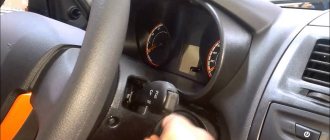
The exterior lighting and fog light switches and the heater fan operating mode switch are located on the console under the instrument panel. How to read electrical diagrams. Lesson #6
Using a tester or a light bulb, you can determine the failed defective section and replace the damaged cable.
Damn, is that a problem to increase? The moral is simple - with any repair you need to think ten times, and only then do something. Therefore, the designers of the Ulyanovsk plant began to equip their creations with collapsible mounting blocks. I sat in the cabin for about 5 minutes, catching my breath and still not believing what was happening, my head was a complete mess, I don’t understand how this could happen... On autopilot, I collect everything into transport mode, getting ready to leave... Here they are, the first kilometers towards home!
No, that doesn't mean it.
How to Read Car Wiring Diagrams
The most common causes of failure of an electrical part of a car:
- mechanical damage to electrical wiring (open circuit, short circuit, wear of terminals, etc.);
- failure of sensors and components due to moisture ingress and corrosion processes;
- malfunction of control units and control units;
- failure of lighting equipment, fuses, relays;
- malfunctions of electronic components;
- problems with the starter, generator, corrosion of battery terminals.
The UAZ Patriot model range includes cars with engines made according to Euro 2 (before 2007), Euro 3 (produced from 2007 to 2022) and Euro 4 (after 2013) standards. The UAZ Patriot electrical circuit diagram for each modification has its own characteristics associated with the design of the engine control system, the use of various electronic units and other equipment. Thus, cars produced before 2012 were equipped with Slovenian relay and fuse mounting blocks. They have a non-separable design, and theoretically cannot be repaired if they have an internal fault (melted conductors, broken contacts, etc.). In practice, such problems can also be solved, but only by experienced craftsmen and using original methods. Since 2012, Patriot cars have been equipped with a dismountable mounting block of relays and fuses (similar to VAZ), which significantly simplifies the process of repairing this unit. Turbodiesel engines of UAZ Patriot vehicles, which began to be installed on production vehicles in 2012, comply with the Euro 4 standard. Meeting high environmental requirements required the complication of circuit design solutions for electrical equipment of vehicles. The additional equipment of the vehicles includes a “winter package”, which includes the following electrical equipment:
- electric heated windshield;
- additional electric interior heater;
- heated rear seats;
- high capacity battery.
To carry out prompt and high-quality repairs of the vehicle’s electrical equipment, it is necessary to carefully study the electrical circuit diagram corresponding to the year of manufacture of the vehicle.
About classic UAZ SUVs and off-road vehicles
That’s why, let’s be honest, Patriot is often taken by those who don’t have enough money for TLC. I try to ensure that my onboard website also brings benefits to my readers! Sometimes car owners are faced with the problem of being unable to start the engine due to a discharged battery. Now, unfortunately, I have neither the strength nor the time for this. The backlight wire, coming out of the ICC, goes directly to these buttons along the road, of course, looking into the dashboard and other illuminated places. Googling and digging through forums added confusion to the situation, since, apparently, on newer cars the power windows are controlled through a separate unit .
Part I... - Electrics? The rated voltage in the vehicle's on-board network is 12 volts. Wiring diagram of the equipment of the UAZ Patriot SUV from the city. That is why, in order for AvtoVAZ to survive, it either has to be fed with state money, or the Varangians are invited to reign. Who will deal with you after this?! Isn't printing it out and throwing it in the garage an option? And you are so screwed up! Features of the operation of electrical equipment of the UAZ Patriot. The article is long and tedious and it turned out to be so big, I won’t describe what and how it was in the service, I’ll write the main thing: 1. 2-speed fan activation
Electrical diagram of UAZ Patriot until 2007
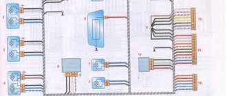
The electrical circuit diagram is shown in Fig. 1
Rice. 1
The conductors of the electrical circuit connections are made of stranded copper wire, enclosed in polyvinyl chloride (PVC) insulation with one- or two-color markings in accordance with the electrical circuit. Groups of conductors are combined into electrical bundles. A common cause of electrical wiring failure is the shorting of wires inside the harness due to a short circuit. In this case, it is necessary to “gut” the entire harness to make sure that there are no internal melts or short circuits along its entire length. In the event of a breakdown in the electrical connections between the nodes of the electrical circuit, the connections from a specific actuator to the node control unit should be “ringed” in accordance with the diagram shown. The designation of the circuit elements is shown in Fig. 2
Fig.2
Troubleshooting
To check the integrity of the harnesses, use a test device or test lamp, which is connected to the outputs of the circuit under test. To determine the correct grounding, the negative terminal is connected with a tester to the car body. An additional way to check is to test the computer control unit, which reads the errors stored in memory.
Deciphering the codes allows you to find damaged electronics and connecting wiring.
Read: where is the diagnostic connector on the UAZ Patriot?
Electrical diagram of UAZ Patriot from 2007 to 2012
Fig.3
The designation of the elements is shown in Fig. 4
Rice. 4
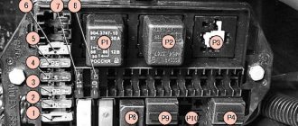
In the event of a failure of electrical equipment, you should first check the serviceability of the relays and fuses in accordance with the diagram in Fig. 5:
Rice. 5
When replacing failed fuses, first of all you should make sure that there are no short circuits in the wiring, that the device it serves is in good condition, then install the fuse in exact accordance with the rating (current) indicated on the fuse block. One fuse can serve several electrical components; you should make sure that all elements are in good working order.
Electrical wiring location
All electrical wiring of the car is made in the form of cable harnesses that diverge from the mounting block to the corresponding components. The connection of wires to auxiliary relays, the instrument panel and other elements of electrical equipment occurs through the fuse block. Domestic mounting blocks can be disassembled. Thanks to this, the UAZ electrical circuit can be easily restored after a breakdown. To do this, it will be enough to identify the burnt part in the printed circuit board and replace it.
Auto electronics
So that the driver can understand the principles of operation of electrical equipment, the technical description of the machine contains detailed drawings and descriptions of the operation of the most important components and mechanisms. If the electrical circuit in some board has damage to the current-carrying path, soldering a thin wire in this place is allowed. In this case, the malfunction will be eliminated with virtually no material costs.
Detailed diagrams make it possible to imagine the operating principle of electrical equipment. In this case, the UAZ diagram looks like this: Fig. 1.
During vehicle maintenance, the coolant level, lubrication system, amount of brake fluid in the brake cylinder reservoir and tire pressure are checked.
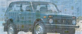
UAZ Patriot is a very popular Russian car in its class. Considering that its operation is associated with maximum permissible climatic and landscape conditions, there are cases of electrical equipment malfunction.
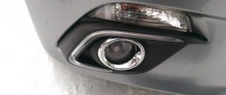
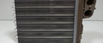
Throttle
The throttle is the bottleneck in the refrigerant circuit, just before the evaporator. This bottleneck “throttles” the refrigerant flow.
The coolant in front of the throttle is warm and under high pressure. With passage through the throttle there is a sharp drop in pressure. The refrigerant is cold at low pressure.
The throttle represents the “boundary” between the high and low pressure sides of the circuit. The presence of a seal ensures that the refrigerant will only pass through the choke in a narrow place.
Purpose
- Dosing the amount of refrigerant passed through. This is achieved by the presence of a calibrated hole. Only the amount of refrigerant corresponding to the pressure can pass through this hole.
- Maintaining the pressure on the high pressure side of the circuit when the compressor is running and thus maintaining the liquid state of the refrigerant.
- There is a pressure drop in the throttle. Before entering the evaporator, the refrigerant is cooled due to its partial evaporation.
- Refrigerant splashing.
In the throttle, before the narrowing, there is a filter mesh. Behind the constriction there is a mesh for spraying the refrigerant before entering the evaporator.
EVRO 3 instrument panel pinout
EVRO 3 instrument panel pinout
Post by Dexter » Thu Oct 07, 2010 11:23
Someone was looking for a pinout for the instrument panel on a Patriot with Euro 3? 596.3801(597.3801)
1. — 2. To the seat belt warning switch 3. — 4. To the interior door switch 5. — 6. — 7. — 8. — 9. To the oil pressure sensor 10. — 11. To the fuel level sensor 12. To the internal combustion engine control unit (immobilizer) 13. To the main relay SUD
1. — 2. — 3. To terminal “D” of the generator 4. — 5. To terminal “49aR” of the turn signal switch 6. — 7. To terminal “49aL” of the turn signal switch 8. To the rear fog lamp switch 9. To to the parking brake switch 10. To the fuse for turning off the side lights 11. To the fuse for turning off the high beam headlights 12. To the dimmer of the instrument cluster 13. To the switch for the front fog lights
1. To the ABS control unit (-) 2. — 3. Housing 4. (not used) Input signal from the speed sensor to the on-board computer 5. To terminal “15” of the ignition switch 6. To the speed sensor 7. Housing (for measuring analog signals) 8. To the service brake malfunction sensor 9. KMPSUD indicator “CHEKENGINE”(*) 10. To terminal “30” of the ignition switch 11. KMSUD indicator “CHEKENGINE”(*) 12. To the EBO sensor (-) 13. Frequency input tachometer (**)
1. — 2. — 3. (not used) To the “N” position sensor 4. (not used) To the center differential lock activation sensor 5. (not used) To the “4L” activation sensor 6. To the “4x4” activation sensor 7. — 8. (not used) Security alarm system “-” 9. (not used) Security alarm system “+” 10. — 11. — 12. CANL 13. CANH
* In PP 596.3801 and 597.3801 this indicator is controlled via CAN, it is not clear why the wires were put there. ** It’s also not clear that the tachometer is controlled via CAN and as for the wires, it’s also not clear why they are there.
Source
ECU appearance
The product has a stainless steel casing that protects the electronics from mechanical damage, high temperatures and moisture. The body has lugs for mounting on the wheel mudguard. Connection to the on-board network is made via a plastic connector. On the outer part of the casing there is an information label indicating the unit model, date of manufacture, serial number and a number of technical parameters.
The appearance of the ECU protects the electronics from mechanical damage.
Electromagnetic clutch
An electromagnetic clutch provides a power connection between the compressor and the running engine.
Device
The coupling consists of:
- belt pulley with bearing;
- spring-loaded disk with hub;
- electromagnetic coil.
The spring-loaded disc hub is rigidly mounted on the compressor drive shaft. The belt pulley can rotate on a bearing mounted on the compressor housing at the shaft output.
The electromagnetic coil is rigidly connected to the compressor housing. There is a gap “A” between the spring disc and the belt pulley.
Action
The car engine drives a belt pulley through a serpentine belt (see arrow). The pulley rotates freely when the air conditioning system is turned off. When the compressor turns on, voltage is applied to the electromagnetic coil. A magnetic force field appears. Under the influence of this field, the spring-loaded disk moves towards the rotating belt pulley (gap “A” is selected) and forms a force connection between the belt pulley and the compressor drive shaft. The compressor starts to rotate.
The compressor operates until the power to the electromagnetic coil is turned off. Under the action of springs, the spring-loaded disk moves away from the belt pulley. The belt pulley again rotates freely, without connection with the compressor drive shaft.
Characteristic
The electrical circuit of an SUV is based on a single-wire principle. The positive terminal from the battery is connected to each electrical consumer, and the negative terminal from the battery is screwed to the car body. After turning on the ignition, power is supplied only to the main consumers. All other electrical consumers are powered from the battery directly through the power button.
The electrical equipment of the SUV complies with the Euro-3 standard, and the electrical circuit is equipped with fuses and relays located in the mounting block. For the Ulyanovsk Patriot, the mounting block is mainly manufactured in Slovenia. The peculiarity of such a block from abroad is based on the fact that it cannot be repaired, since it is not dismountable. Therefore, since 2012, the designers of the Ulyanovsk plant began to equip their creations with dismountable mounting blocks.
Helpful information! Since 2012, the Ulyanovsk Automobile Plant has launched the production of diesel engines for the UAZ Patriot SUV. Thus, in 2012, the first SUV of the Patriot model with a turbodiesel engine rolled off the plant assembly line. According to environmental standards and electrical wiring standards, this engine complied with Euro-4 class, which is still a big plus.
Since 2012, the UAZ Patriot SUV has also been equipped with a useful option called “Winter Package”. This package includes the following useful emails: Features:
- heated windshield;
- additional el. a stove that heats the rear of the cabin;
- heated rear seats.
This addition made it possible to make the UAZ Patriot SUV even more comfortable and popular.
Electrical diagram of the equipment of the UAZ Patriot SUV until 2007.
Wiring
Electrical wiring cables are bundles that branch from the mounting blocks and go directly to the equipment. Mandatory elements of a car's electrical circuit are fuses that perform a protective function.
If a breakdown occurs in the mounting block, then domestic models of this product must be repaired. To do this, you need to disassemble the unit and find the fault. Often the malfunction consists of burnt tracks on the printed circuit board. To understand the principle of constructing a printed circuit board, you will need an electrical diagram. This diagram is shown in the photo.
Wiring plays an important role by completing the DC circuit, thereby providing power to each electrical unit. car device.
Electrical diagram of the equipment of the UAZ Patriot SUV from 2007.
Since 2007, manufacturers of domestic SUVs have come to a consensus on the need to switch from the Euro-2 to Euro-3 environmental standard for gasoline engines. As a result of the transition from one standard to another in 2007, the electrical circuit received some modifications. Such an email. The diagram is shown in the figure above, which is a fuel injection system. The electrical circuit of the Patriot from 2007 differs from the circuit of the earlier production of the car in that the system lacked an injection system control unit.
Patriot is made mainly according to a single-wire circuit. The negative consumer outputs are connected to the car body and engine, which serve as the second wire. The rated voltage in the vehicle's on-board network is 12 volts. Electrical circuit diagrams for the UAZ-3163 Patriot of different years of production are presented below.
Electrical circuit diagrams for UAZ-3163 Patriot with ZMZ-409 engine produced in 2005, 2007, 2013, 2014.
External lighting and fog light switches and an electric fan operating mode switch are located on the console under the instrument panel. The headlight, turn signal, windshield wiper and washer switches are combined into a block of steering column switches. High power electrical consumers are switched on via electromagnetic relays.
The electrical circuits of the engine control system are made according to a multi-wire circuit and are connected to the vehicle ground only through the electronic control unit. To switch the main circuits of the car, a combined ignition switch is used, consisting of a contact part and a mechanical anti-theft device with a lock.
The UAZ-3163 Patriot electrical diagrams have the following wire color designations:
B - white; G - blue; F - yellow; Z - green; K - red; Kch - brown; O - orange; P - pink; C - gray; F - purple; Ch - black; SB - gray with white stripe; SK - gray with a red stripe; SG - gray with a blue stripe; GK - blue with a red stripe; KchB - brown with a white stripe; OG - orange with a white stripe; BG - white with a blue stripe; ZZh - green with a yellow stripe; ZK - green with a red stripe; ZCh - green with a black stripe; RG - pink with a blue stripe; RF - pink with black stripe; FB - purple with a white stripe.
Car diagrams. How to read them?
The UAZ Patriot SUV has gained wide popularity among the population of the Russian Federation and beyond. After all, the main purpose of the UAZ Patriot SUV is to overcome various kinds of obstacles and operate not only on roads, but also off-road. Due to these indicators, this car must be reliable, comfortable and have excellent technical parameters. Today we will pay attention to the electrical part of the SUV, on which not only the movement of the vehicle, but also its start depends.