I decided to check the ADC on the mass air flow sensor. full article here. mayvaz.ucoz.ru/index/datc…hoda_vazdukhaju_dmvr/0-23 1. Turn on the tester in DC voltage measurement mode, and set the measurement limit to 2 Volts. We find in the sensor connector a yellow wire - output (closest to the windshield) and a green wire - ground (third from the same edge). These are the sensor pins we need. In systems of different years, colors may change (! and the connector may already be changed), only the location of the pins remains unchanged. To assess the condition of the mass air flow sensor, it is necessary to measure the voltage between the indicated terminals with the ignition on, but NOT starting the engine! The diameter of the tester probes allows you to penetrate through the rubber seals of the connector, along the specified wires, without disturbing their insulation, reaching the contacts themselves and without causing harm to the seals themselves. It will be useful to spray HP grease on the probes. Turn on the ignition, connect the tester, take readings. The same readings can be taken without a tester from the on-board computer display, if anyone has one. In the “voltage from sensors” parameter group. Designated Udmrv=…
2. Evaluate the results. The voltage at the output of a working sensor in the “out of the package” state is 0.996…1.01 Volts. During operation, it gradually changes and, as a rule, increases. By increasing this voltage, one can quite confidently judge the degree of “wear” of the sensor. A voltage within the above range is the best result of this test. Further options are possible: 1.01…1.02 - a completely working sensor, very good. 1.02…1.03 is also acceptable, but the sensor is no longer young. 1.03…1.04 - most of the resource is already behind, you can plan for a quick replacement. 1.04…1.05 - clearly a tired sensor, it has already served its purpose. If your budget allows, feel free to change it. 1.05...and higher are a source of problems, it’s high time to replace them.
Measured:
between the yellow and battery negative 1.052 V, (apparently the masses need to be cleaned) between the yellow and green wire 1.014 V. (sensor is live)
It is best to take the ground from the green wire, because this is exactly the voltage that the controller sees.
Here I found useful information on typical parameters. Made essentially as a note to myself.
For many novice diagnosticians and ordinary car enthusiasts who are interested in the topic of diagnostics, information about typical engine parameters will be useful. Since VAZ car engines are the most common and easiest to repair, we’ll start with them. What should you pay attention to first when analyzing engine operating parameters? 1. The engine is stopped. 1.1 Coolant and air temperature sensors (if equipped). The temperature is checked to ensure that the readings correspond to the actual engine and air temperatures. It is better to check using a non-contact thermometer. By the way, one of the most reliable in the injection system of VAZ engines are temperature sensors.
1.2 Throttle position (except for systems with an electronic gas pedal). The gas pedal is released - 0%, the accelerator is pressed - according to the opening of the throttle valve. We played with the gas pedal, released it - it should also remain 0%, while the ADC with a dpdz of about 0.5V. If the opening angle jumps from 0 to 1-2%, then as a rule this is a sign of a worn out valve. Less common are faults in the sensor wiring. With the gas pedal fully pressed, some units will show 100% opening (such as January 5.1, January 7.2), while others such as Bosch MP 7.0 will show only 75%. This is fine.
1.3 MAF ADC channel in rest mode: 0.996/1.016 V - normal, up to 1.035 V is still acceptable, everything above is already a reason to think about replacing the mass air flow sensor. Injection systems equipped with feedback from an oxygen sensor are able to correct, to some extent, incorrect readings of the mass air flow sensor, but there is a limit to everything, so you should not delay replacing this sensor if it is already worn out.
2. The engine is idling.
2.1 Idle speed. Typically this is 800 - 850 rpm with a fully warmed up engine. The idle speed value depends on the engine temperature and is set in the engine control program.
2.2 Mass air flow. For 8-valve engines, the typical value is 8-10 kg/h, for 16-valve engines - 7-9.5 kg/h with a fully warmed-up engine at idle. For the M73 ECU these values are slightly higher due to a design feature.
2.3 Length of injection time. For phased injection, the typical value is 3.3 - 4.1 ms. For simultaneous – 2.1 – 2.4 ms. Actually, the injection time itself is not as important as its correction.
Purpose and explanation of the abbreviation
Flow meters, also known as volume meters or mass air flow meters (not to be confused with mass air flow meters and mass air flow sensors), are installed in diesel or gasoline-powered vehicles. The location of this sensor is not difficult to find, since it controls the air supply, you should look for it in the corresponding system, namely, after the air filter, on the way to the throttle valve (DZ).
Installation location of mass air flow sensor on Gazelle 405
The device is connected to the engine control unit. In cases where the mass air flow sensor is in a faulty condition or is missing, a rough calculation can be made based on the position of the air flow sensor. But with this measurement method it is impossible to ensure high accuracy, which will immediately lead to excessive fuel consumption. This once again indicates the key role of the flow meter in calculating the fuel mass supplied through the injectors.
In addition to information from the mass air flow sensor, the control unit also processes data coming from the following devices: camshaft sensor (camshaft sensor), DD (knock meter), remote sensor, cooling system temperature sensor, acidity meter (lambda probe), etc.
This is interesting: What does g12 antifreeze mean?
Symptoms of a problem
The mass air flow sensor is located in the air duct near the air filter. It is designed to determine the amount of incoming air. Depending on its readings, the control unit will show how much fuel is needed to form a high-quality fuel mixture. The normal ratio is 1:14. Therefore, the quality of the fuel-air mixture depends on the correct readings of the flow meter.
The high-quality operation of the mass air flow sensor depends largely on the cleanliness of the air filter. Therefore, if symptoms of a malfunction of the mass air flow sensor appear, you should first check the air filter before making repairs. The flow meter is usually beyond repair. If it is faulty, it is replaced with a new device. But its cost is quite high, so you should first make sure that the causes of the problems are in the sensor and not in other malfunctions of the machine.
The signal for diagnosis is the following symptoms of a malfunction of the mass air flow sensor:
- Check Engine appears on the instrument panel;
- an error is displayed indicating a low level of the mass air flow sensor signal;
- the engine starts poorly when cold, accelerates very slowly, stalls, and its power drops;
- high level of fuel consumption;
- the engine is unstable at idle;
- the engine stalls when changing gears;
- The rpms are either high or low.
There are other symptoms of a “dying” sensor. For example, it may have cracks in the corrugated hose that connects the throttle body to the sensor. If the engine stalls, there may be a power problem or damaged wiring. This is a signal to check the electrical wiring. If malfunctions are detected, the machine's electrical system must be repaired.
Interchangeability
This issue is quite relevant, especially taking into account the cost of original products from the imported automobile industry. But it’s not so simple here; let’s give an example. In the first production models of the Gorky Automobile Plant, the injection Volgas were equipped with a BOSCH air flow sensor. Somewhat later, imported sensors and controllers replaced domestic products.
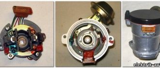
A – imported filament air flow sensor manufactured by Bosh (pbt-gf30) and its domestic analogues B – JSCB “Impuls” and C – APZ
Structurally, these products were practically no different with the exception of several design features, namely:
- The diameter of the wire used in a wirewound thermistor. Bosch products have a diameter of 0.07 mm, and domestic products have a diameter of 0.10 mm.
- The method of fastening the wire differs in the type of welding. For imported sensors this is resistance welding, for domestic products it is laser welding.
- Shape of a thread thermistor. Bosh has a U-shaped geometry, APZ produces devices with a V-shaped thread, and products from JSC Impulse are distinguished by the square shape of the thread suspension.
All the sensors given as an example were interchangeable until the Gorky Automobile Plant switched to film analogues. The reasons for the transition were described above.
Film air flow sensor Siemens for GAZ 31105
It makes no sense to give a domestic analogue to the sensor shown in the figure, since outwardly it is practically no different.
It should be noted that when switching from filament devices to film devices, most likely, it will be necessary to change the entire system, namely: the sensor itself, the connecting wire from it to the ECU, and, in fact, the controller itself. In some cases, the control can be adapted (reflashed) to work with another sensor. This problem is due to the fact that most filament flowmeters send analog signals, while film flowmeters send digital signals.
It should be noted that the first production VAZ cars with an injection engine were equipped with a filament air flow sensor (made by GM) with a digital output; examples include models 2107, 2109, 2110, etc. Now they are equipped with air flow sensor BOSCH 0 280 218 004 .
To select analogues, you can use information from official sources or thematic forums. As an example, below is a table of the interchangeability of mass air flow sensors for VAZ cars.
Compatibility table for mass air flow sensor for the VAZ model range
The presented table clearly shows that, for example, the MAF sensor 0-280-218-116 is compatible with VAZ 21124 and 21214 engines, but is not suitable for 2114, 2112 (including those with 16 valves). Accordingly, you can find information on other VAZ models (for example, Lada Granta, Kalina, Priora, 21099, 2115, Chevrolet Niva, etc.).
As a rule, there will be no problems with other brands of cars of domestic or joint production (UAZ Patriot ZMZ 409, Daewoo Lanos or Nexia), choosing a replacement mass air flow sensor for them will not be a problem, the same applies to products of the Chinese automobile industry (KIA Ceed, Spectra, Sportage etc.). But in this case, there is a high probability that the MAF pinout may not match; a soldering iron will help correct the situation.
The situation is much more complicated with European, American and Japanese cars. Therefore, if you have a Toyota, Volkswagen Passat, Subaru, Mercedes, Ford Focus, Nissan Premiere P12, Renault Megane or another European, American or Japanese car, before replacing the mass air flow sensor, you need to carefully weigh all the solution options.
If you are interested, you can search online for an epic about an attempt to replace the “native” air meter with an analogue on a Nissan Almera H16. One attempt resulted in excessive fuel consumption even at idle.
In some cases, searching for an analogue one will be justified, especially if you take into account the cost of the “native” VU meter (for example, the BMW E160 or Nissan X-Trail T30).
Let's compare architectures
At the moment, there are many different ADC architectures in the world.
Each of them has its own advantages and disadvantages. There is no architecture that would achieve the maximum values of all the parameters described above. Let's analyze what maximum speed and resolution parameters the companies producing ADCs were able to achieve. We will also evaluate the advantages and disadvantages of each architecture (you can read more about the various architectures in the article on Habr). Architecture comparison table
| Architecture type | Advantages | Flaws | Maximum resolution | Maximum sampling rate |
| flash | Fast converter. The conversion is carried out in one clock cycle. | High power consumption. Limited resolution. Requires a large crystal area (comparators). It is difficult to coordinate a large number of elements (as a result, low yield). | 14 bit 128 kSa/s AD679 | 3 bit 26 GS/s HMCAD5831 |
| folding-interpolated | Fast converter. The conversion is carried out in one clock cycle. Requires fewer comparators due to preliminary “convolution” of the entire processing range into a narrower range. Occupies less space. | Errors associated with the nonlinearity of the convolution block. Delay for establishing levels in the convolution block, which reduces the maximum fs. Medium resolution. | 12 bit 6.4 GS/s ADC12DL3200 | 12 bit 6.4 GS/s ADC12DL3200 |
| SAR | High accuracy. Low power consumption. Easy to use. | Limited speed. | 32 bit 1 MSa/s LTC2500 | 10 bit 40 MSa/s XRD64L43 |
| pipeline | Fast converter. Highest accuracy among fast ADCs. Doesn't take up a large area. Has lower consumption among similar fast converters. | Pipeline delay. | 24 bit 192 kSa/s AK5386 | 12 bit 10.25 GS/s AD9213 |
| dual-slope | Average conversion accuracy. Simplicity of design. Low consumption. Resistance to changes in environmental factors. | Processes low frequency Signals (low fs). Mediocre resolution. | 12+sign bit 10 S/s TC7109 | 5+sign bits 200 kSa/s HI3-7159 |
| ∑-Δ | The highest conversion accuracy thanks to the “Noise shaping” effect (specific filtering of quantization noise) and oversampling. | Cannot work with wideband signal. | 32 bits 769 kSa/s AK5554 | 12 bit 200MS/s ADRV9009 |
I took the information for the table from the arrow website, so if I missed anything, please correct it in the comments.
How to trick a broken mass air flow sensor using a resistor
Let's consider the “restoration” option using the example of a VAZ 2110. After an unreasonable increase in fuel consumption, you decide to check the mass flow sensor with a multimeter. The readings at rest significantly exceed the ideal “no higher than 1.02 V” and even the acceptable “1.05 V”.
Accordingly, the engine sees a lean fuel-air mixture and adds more gasoline to the ratio. The result is an increase in consumption without an increase in power.
How to reduce the voltage at the ADC output of a flow meter? We know that based on the calibration of the mass air flow sensor in the electronic engine control unit, each value in volts corresponds to the volume of air in kg/hour.
How to reduce tension? Any novice electrician will tell you that you need to add resistance (additional resistor). Of course, it will not be possible to guess (or even calculate) the required value, so it is better to use a variable resistor in the range from 1 kOhm to 2 kOhm. Old Soviet SP-1 alternators are suitable. They will not fall apart from moisture or temperature under the hood.
The resistor is connected to the break in the wire running from contact No. 5 of the VAZ mass air flow sensor to the engine ECU controller.
Important: All work on the wiring harness is performed with the battery disconnected.
After connecting, we check the flow meter at rest:
- connect the multimeter to contacts No. 3 (ground) and No. 5 (ADC signal) of the mass air flow sensor connector;
- turn on the ignition without starting the engine;
- By tightening the variable resistor regulator, we achieve a value of 1 volt.
After this, it is necessary to mechanically secure the resistor so that it does not break during movement. We carry out a test drive and make sure that gasoline consumption is reduced.
What does a faulty air flow sensor cause?
Operating an engine with an inoperative/faulty flow meter causes detonation of the fuel mixture in the combustion chamber. This affects the operation of the crank mechanism (crank mechanism) and destroys the piston surface, which can cause a “wedge” in the engine.
What indications should a working mass air flow sensor give?
The voltage of the analog-to-digital converter (ADC) of the flow meter when the engine is not running should be 0.996 V. Indicators of 1.016 and 1.025 V are acceptable, but if they reach more than 1.035 volts, it means that the sensing element of the mass air flow sensor is clogged.
To accurately determine the degree of deviation of the operating flow meter values from normal values, it is necessary to evaluate the engine operation at different speeds.
For example, for an injection 1.5-liter VAZ 2111 engine, if it is in good condition, at idle (860–920 rpm) the correct readings are 9.5–10 kg/hour, and at 2 thousand rpm - 19 –21 kg/hour. If the flow meter at 2 thousand rpm shows about 17–18 kg, then the car will drive stably. If the values are from 22 to 24 kg/hour, then the vehicle will move steadily, but the fuel consumption per 100 km will be approximately 10–11 liters. In addition, the car will have difficulty starting in cold weather due to fuel overflow when the engine warms up.
How to deceive the mass air flow sensor using ECU firmware
The good thing about the previous method is that its implementation does not require complex equipment or painstaking work. If you were able to check the voltage at the output of the flow meter with a multimeter (which means you at least have one), and know how to hold a soldering iron in your hands, installing a resistor in the wire gap will not be difficult. However, the dependence of voltage on air flow mass is nonlinear. And when the throttle valve opens, the error of the signal corrected by the resistor at rest will increase. Accordingly, the fuel-air mixture will not be ideal.
This means that you need to adjust the MAF calibration in the ECU firmware.
Attention! If you do not have experience working with car software, it is better to entrust this operation to professionals.
- We install the specialized tuning program “DFID Corrector” on the laptop.
- We connect the car scanner to the OBD-II connector and establish communication between the ECU and the computer.
Important! During operations with the ECU controller firmware, the 12 volt power supply should not be lost. Therefore, you need to make sure that the battery is fully charged.
- We adjust the voltage of the MAF ADC at rest (air mass 0 kg/hour) to the required 1 V.
- Save the firmware changes.
After calibration, the data on mass air flow will be correct throughout the entire engine speed range.
Attention: After you install a new flow meter, you must return the calibration to the factory (standard) state.
This is interesting: What gap should be on the Hyundai Solaris on the spark plugs
Features, diagnostics and replacement of elements of injection systems on VAZ cars
Below we will look at the main controllers!
Hall
There are several options for how you can check the Hall sensor of a VAZ:
- Use a known working device for diagnostics and install it instead of the standard one. If after replacement the problems in engine operation cease, this indicates a malfunction of the regulator.
- Using a tester, diagnose the controller voltage at its terminals. During normal operation of the device, the voltage should be from 0.4 to 11 volts.
Checking and repairing at home
There are eight ways to independently check amplitude and frequency mass flow sensors.
Method No. 1 - disabling the air flow meter
The method consists of disconnecting the sensor from the fuel system of the car and checking the functionality of the system without it. To do this, you need to disconnect the device from the connector and start the engine. Without a mass air flow sensor, the controller receives a signal to switch to emergency operation mode. It prepares the air-fuel mixture only based on the throttle position. If the car moves faster and does not stall, it means that the device is faulty and requires repair or replacement.
Method No. 2 - flashing the electronic control unit
If the standard firmware has been changed, then it is unknown what reaction of the controller is programmed in it in case of an emergency. In this case, you should try to insert a 1mm thick plate under the throttle stop. The turnover should increase. Now you need to pull out the chip from the air flow meter. If the power unit continues to work, then the cause of the malfunction is the firmware.
Method No. 3 - installing a working sensor
Install a known good part and start the engine. If after replacement it begins to work better, the motor does not stall, then replacement or repair of the device is required.
Method No. 4 - visual inspection
To do this, use a Phillips screwdriver to unscrew the clamp holding the air collector corrugation. Then you need to disconnect the corrugation and inspect the internal surfaces of the air collector corrugation and the sensor.
Inspection of duct corrugation
There should be no traces of oil or condensation on them, the surfaces should be dry and clean. If you do not take care of the air filter and change it rarely, then dirt can get on the sensitive element of the sensor and cause it to break. This is the most common malfunction. Traces of oil may appear in the flow meter if the oil level in the crankcase is high, or if the oil sump of the crankcase ventilation system is clogged. If necessary, you need to clean the surfaces using special cleaning products.
Method No. 5 - checking the mass air flow sensor with a multimeter
To do this, you need to turn on the tester in a mode in which constant voltage is checked. The limit value for measurements should be set to 2V.
DMRV operation diagram
- The yellow wire is located closer to the windshield. It serves as an input for a signal from the flow meter.
- The white-gray wire is the sensor voltage output.
- The black and pink wire leads to the main relay.
- The green wire is used to ground the sensors, that is, it goes to ground.
The wires may have different colors, but their location is unchanged. To check, you need to turn on the ignition, but do not start the car. The red probe from the multimeter must be connected to the yellow wire, and the black one must be connected to ground, that is, to the green wire. We measure the voltage between these two outputs. Multimeter probes make it possible to connect without disturbing the insulation of the wires.
On the new device, the output voltage ranges from 0.996 to 1.01 V.
During operation, this voltage gradually increases and by its value one can judge the wear of the flow meter:
- if the sensor is in good condition, the voltage is from 1.01 to 1.02 V;
- in satisfactory condition - from 1.02 to 1.03 V;
- the sensor resource ends if the voltage is in the range from 1.03 to 1.04 V;
- a value in the range from 1.04 to 1.05 indicates a near-death state; if there are no contraindications, then you can continue to use the sensor;
- if the voltage exceeds 1.05 V, the mass air flow sensor requires replacement.
ADC flow meter readings
Diagnostics of the mass air flow sensor "Tseshkoy" is not difficult and can be done with your own hands.
If there is dirt on the removed sensor, you can clean it yourself. You can use WD-40 to wash it. To clean the mass air flow sensor, you must first remove the pipe from it, and then dismantle the device itself. Inside the device there is a mesh and several wires - sensors.
They need to be sprayed with cleaning agent and washed. Then let the liquid dry. If dirt remains, the procedure should be repeated. You need to clean the pipe with the same product. It must be free of dirt and oil stains. After replacing the air filter, all parts must be returned to their place. After the cleaning procedure, the device’s functionality can be restored to 80%, the error about the reduced sensor signal level disappears (the author of the video is “24 hours”).
Flushing the sensor will help avoid costly repairs.
Method No. 6 - checking with a scanner
- Install a diagnostic program on your phone (smartphone), tablet or laptop computer (for example, Torque Pro, Opendiag, BMWhat, OBD Auto Doctor).
- Connect your mobile device or laptop to the diagnostic connector located on the vehicle's electronic control unit using a special cable, Bluetooth channel.
- Launch the diagnostic utility on your phone (smartphone) or computer.
- Wait until the program finishes scanning all vehicle components. As a result, the utility will check the serviceability of each vehicle unit.
- Decipher the error codes that the program will show after the diagnostics are completed.
To perform this method, testers are used:
Method No. 7 – checking by Vasya the Diagnosticist
To identify a malfunction of the mass air flow sensor without removing it from the car, you need to:
- Install a program called “VASYA diagnostician” on your laptop (laptop) and run it.
- Connect the adapter to the vehicle's diagnostic port.
- Select the item “Electronics 1” or “01 – Engine electronics” from the “Control unit” tabs to connect to the vehicle’s control unit.
- Go to “Custom Groups”.
- Select 211, 212 (passport value) and 213 (current value).
- Compare current indicators with passport data. If the deviations are high, then it is necessary to replace the mass air flow sensor.
Method No. 8 - using a motor tester
This method is used to test frequency-type flowmeters.
To check the mass air flow sensor with a motor tester (oscilloscope), you need to connect it to the sensor (depending on the car brand) and start the engine.
Mass air flow sensor check parameters:
- transient time when the ignition is on;
- air consumption readings at idle and a sharp increase in engine speed;
- voltage in the sensor network.
The output data is individual for different types of engines. Before diagnosis, you should check the current indications with an official representative.
ADC with parallel conversion of input analog signal
In the parallel method, the input voltage is simultaneously compared to n reference voltages and determined between which two reference voltages it lies. In this case, the result is obtained quickly, but the scheme turns out to be quite complex.
Operating principle of the ADC (Fig. 3.93)
When Uin = 0, since for all op-amps the voltage difference (U+ − U−) < 0 (U+, U− are voltages relative to the common point of the non-inverting and inverting input, respectively), the voltages at the output of all op-amps are equal to −Epit at the outputs of the encoding converter ( KP) Z0, Z1, Z2 are set to zero. If Uin > 0.5U, but less than 3/2U, only for the lower op-amp (U+ − U−) > 0 and only at its output does the voltage +Epit appear, which leads to the appearance of the following signals at the outputs of the CP: Z0 = 1, Z2 = Zl = 0. If Uin > 3/2U, but less than 5/2U, then the voltage +Epit appears at the output of the two lower op-amps, which leads to the appearance of code 010 at the outputs of the CP, etc.
Watch an interesting video about the operation of the ADC:
Replacing the air flow sensor
To replace the sensor with your own hands, you need to prepare a shaped screwdriver and a “10” key.
The replacement procedure consists of the following steps:
- First you need to turn off the ignition and open the hood.
- Then you need to disconnect the negative terminal on the battery.
- At the next stage, you need to loosen the clamp with which the corrugation is attached to the mass air flow sensor.
- Next, remove the corrugation from the pipe.
- Then you need to bend the comb and disconnect the sensor connector.
Disconnecting the sensor connector
- Then, using a key set to “10”, you need to unscrew the sensor mounting bolts to the air filter housing.
- Now you can remove the mass air flow sensor.
- Installing the sensor yourself is carried out in the reverse order.
Thus, if the car stalls and has all the signs of a breakdown of the mass air flow sensor, then before you start repairing it, you should check the level of its signal, it should not be low, perform a full diagnosis of the car and repair all faulty components and parts.
It is important to undergo regular vehicle inspections and perform timely maintenance, then the parts and components will last longer.
Which oscilloscope to choose for car diagnostics
Let's consider the most convenient and informative devices.
USB Autoscope Postolovsky
In first place in the ranking of practitioners is the Postolovsky USB Autoscope IV oscilloscope. Has extensive diagnostic functions.
Advantages
- Professional scripts from Andrey Shulgin.
- User-friendly interface.
- Wide measurement range from 6 to 300 volts.
- Processing scripts automatically.
- Informative efficiency script for CSS cylinders, showing the operation of injectors and ignition systems.
- Test battery, generator, starter. Shows faults automatically. Easy process of reading characteristics: it is enough to have access to the positive or negative terminals of the battery.
- Cylinder pressure test. Shows the marks of the gas distribution system, whether the phases are correct. Detects a spun drive disk.
Complete documentation for operating the device. Scripts and connection diagrams are described in detail. There are video instructions on the manufacturer's website. Responsive support.
Motodoc 3
Second in the list of oscilloscope ratings for diagnosing a car of any brand is Motodok 3. It has similar characteristics.
Advantages and disadvantages
- Script by Andrey Shulgin for cylinder efficiency. There are some disadvantages to synchronization with some cars that have a weak signal from the crankshaft sensor. But this is offset by convenience and fast operation.
- Connections over any distance via RJ 45 cable.
- The quality of the picture during diagnostics, which is not unimportant when working.
- Detailed documentation on the manufacturer's website.
As an example, only two oscilloscopes for car diagnostics are shown. There are other devices: they differ in price and manufacturer, but the measurement principle is the same. The most important thing is to have experience in reading waveforms for each make of car.
ADC codes
ADC code parameters relate to analog sensors of the control system:
Physically, ADC codes reflect the voltage that the sensor produces. Typically, these parameters are used to test sensor circuits. If fault codes occur associated with a low or high signal level of such a sensor, then the control system operates in backup modes. In this case, the value of the parameter related to this sensor is selected either from the emergency table or calculated using specified formulas, for example, the coolant temperature with a faulty temperature sensor increases during engine operation.
If, during a physical change in the parameter measured by the sensor, the ADC code remains a constant value, then the electrical circuit connecting the sensor is inoperative.
ADC values are dimensionless, but for the user in scanner testers they are translated into the voltage that a particular sensor produces.
Therefore, using an ADC code, for example, from an L-probe sensor, you can more clearly evaluate the work in the feedback loop system to maintain the stoichiometric composition of the mixture. If the L-probe sensor is inoperative, then the ADC code is in the range of 0.4-0.7V.
The ADC code value (output voltage) from the throttle position sensor can indicate the lower limit at which the system detects sensor error. A throttle position equal to zero corresponds to a voltage from the sensor of 0.52 V.
When the ignition is on, the output voltage from the mass flow sensor (ADC code) should be 1.00V.
The temperature sensor, throttle position sensor, mass flow sensor are powered by a voltage of 5.00V, which is supplied by the control unit. If the control unit produces an unstable voltage, then the sensor readings will change and the behavior of the system in this case is unpredictable.
Static parameters
- Maximum
(
Vref
)
and minimum
(usually 0)
input signal levels
- set the range of the conversion scale against which the input signal will be evaluated (Fig. 1).
This parameter can also be designated as FS
- full scale. For a differential ADC, the scale is defined from -Vref to +Vref, however, for simplicity, we will further consider only single-ended scales. - Bit capacity
(
N
) is the capacity of the output code, characterizing the number of discrete values () that the converter can produce at the output (Fig. 1). - Current consumption
(
Idd
) strongly depends on the conversion frequency, so it is better to look for information about this parameter on the corresponding graph. - LSB
(
LSB
) -
Least Significant Bit
- the minimum input voltage allowed by the ADC (essentially a single step in the conversion scale). Determined by the formula: (Fig. 1). - Offset error
(
offset error
) – is defined as the deviation of the actual ADC transfer characteristic from the ideal ADC transfer characteristic at the initial point of the scale. Measured in fractions of LSB. With an offset error, the transition of the output code from 0 to 1 occurs at an input voltage different from 0.5LSB (Fig. 2).Rice.
2: Offset error There is another version of the quantizer, when the transition is carried out at integer LSB values (its characteristic will be shifted relative to the first option, which is presented in Figure 2). Both of these quantizers are equal, and for simplicity, we will further consider only the first option. - Gain Error
(
gain error
) – is defined as the deviation of the midpoint of the last conversion step (which corresponds to the input voltage Vref) of a real ADC from the midpoint of the last conversion step of an ideal ADC after offset error compensation (Fig. 3).Rice. 3: Gain error
- Differential nonlinearity
(
DNL
—
Differential nonlinearity
) is the deviation of the step width on the transfer characteristic of a real ADC from the nominal step width of an ideal converter. Due to differential nonlinearity, quantization steps have different widths (Fig. 4).Rice.
4: Differential nonlinearity For the 3-bit ADC from Figure 4: - Integral nonlinearity
(
INL
—
Integral nonlinearity
) – vertical difference between the real and ideal transformation characteristics (Fig. 5). INL can be interpreted as the sum of DNL. A negative INL indicates that the actual performance is below the ideal performance at that point on the scale. For a positive INL, the actual performance is higher than the ideal one. The DNL distribution determines the integral nonlinearity of the ADC.Rice. 5: Integral nonlinearity
- Total Unadjusted Error
(
TUE
-
Total Unadjusted Error
) is an absolute error that includes the following errors: quantization, offset, gain and nonlinearity. In other words, it is the maximum deviation between the actual and ideal conversion characteristics. For an ideal ADC, TUE = 0.5LSB, due to quantization error (or quantization noise - occurs due to rounding of the analog signal value that corresponds to the digital code). Gain and offset errors are usually the largest contributors to the absolute error. However, from a dynamic perspective (see below), offset and gain errors are negligible because they do not generate nonlinear distortion.
Description of ADS1115 registers
The ADC has only 4 internal registers, all registers are 16-bit, respectively, for each write/read session, 2 information bytes are transmitted via the I2C interface (except for the register address byte). The registers are described in the table below:
| Address | Name | Register description |
| 0x00 | Conversion register | Conversion result storage register |
| 0x01 | Config register | Configuration register |
| 0x02 | Lo_thresh register | Setpoint register, minimum value |
| 0x03 | Hi_thresh register | Setpoint register, maximum value |
The configuration register is used to control the ADC; the register is described in the table below:
| Bit | Bit name | Bit value | Description |
| 15 | OS. The bit defines the state of the device and can only be written in low power mode | For recording | |
| 0 | No effect | ||
| 1 | Start conversion, for single conversion mode (low consumption) | ||
| For reading | |||
| 0 | Conversion in progress | ||
| 1 | Conversion complete | ||
| 14-12 | MUX. Multiplexer setup | 000 | AINp=AIN0 and AINn=AIN1 (default) |
| 001 | AINp=AIN0 and AINn=AIN3 | ||
| 010 | AINp=AIN1 and AINn=AIN3 | ||
| 011 | AINp=AIN2 and AINn=AIN3 | ||
| 100 | AINp=AIN0 and AINn=GND | ||
| 101 | AINp=AIN1 and AINn=GND | ||
| 110 | AINp=AIN2 and AINn=GND | ||
| 111 | AINp=AIN3 and AINn=GND | ||
| 11-9 | P.G.A. Amplifier Gain | 000 | FS=±6.144 V |
| 001 | FS=±4.096 V | ||
| 010 | FS=±2.048 V (default) | ||
| 011 | FS=±1.024 V | ||
| 100 | FS=±0.512 V | ||
| 101 | FS =±0.256 V | ||
| 110 | FS =±0.256 V | ||
| 111 | FS =±0.256 V | ||
| 8 | MODE. Operating mode | 0 | Continuous transformation |
| 1 | Single conversion, low consumption mode (default) | ||
| 7-5 | D.R. Sampling frequency | 000 | 8 Hz |
| 001 | 16 Hz | ||
| 010 | 32 Hz | ||
| 011 | 64 Hz | ||
| 100 | 128 Hz (default) | ||
| 101 | 250 Hz | ||
| 110 | 475 Hz | ||
| 111 | 860 Hz | ||
| 4 | COMP_MODE. Comparator type | 0 | Comparator with hysteresis (default) |
| 1 | Comparator without hysteresis | ||
| 3 | COMP_POL. Comparator polarity | 0 | Low active level (default) |
| 1 | High active level | ||
| 2 | COMP_LAT. Comparator mode | 0 | Comparator without latch (default) |
| 1 | Latch Comparator | ||
| 1-0 | COMP_QUE. Comparator control | 00 | Setting the output signal after one conversion |
| 01 | Setting the output signal after two conversions | ||
| 10 | Setting the output signal after four conversions | ||
| 11 | Comparator disabled (default) |
ADC bandwidth and subsampling (undersamling/sub-sampling)
Converter bandwidth
(
FPBW
-
Full Power (Analog) Bandwidth
). Typically the converter bandwidth is several Nyquist zones. This parameter should be in the specification, but if it is not, you can try to independently estimate the minimum possible bandwidth for a given ADC. During the sampling period, the UVH capacitance must be charged with an accuracy of 1 LSB. If the sampling period is , then the sampling error of the full scale signal is equal to: Solving for t, we obtain: Assuming that , we determine the minimum ADC bandwidth (for ): For example, for a 16-bit ADC with a sampling rate of 80 MSa/s and a scale of 2 V, the lower limit for the bandwidth calculated using this formula will be FPBW = 282 MHz.
Analog Bandwidth is a very important parameter when building systems that operate in subsampling mode. Let's explain this in more detail. According to the Nyquist criterion, the spectrum width of the processed signal must be at least 2 times less than the sampling frequency to avoid aliasing. What is important here is that it is the bandwidth, and not just the maximum frequency of the signal. For example, a signal whose spectrum is located entirely in the 6th Nyquist zone can theoretically be sampled without loss of information (Fig. 11). By limiting the spectrum of this signal with an anti-aliasing filter, it can be fed to a sampler with a frequency of fs. As a result, the signal will be reflected in each zone.
Rice.
11: undersampling Spectrum transfer property during sampling
Undersampling or sub-sampling occurs due to the properties of sampling. Let's consider an example, let there be a signal a(t) and its spectral density (Fig. 12). It is necessary to find the spectral density of the signal after sampling the signal.
Fig. 12: sampling of a continuous signal
Based on the filtering property of the delta function:
After sampling: where
Using the Rayleigh formula, we calculate the spectrum:
From this expression it follows that the signal spectrum will be repeated in all Nyquist zones. So, if you have a good anti-aliasing filter, then by observing the Nyquist criterion, you can digitize a signal with a sampling frequency much lower than the ADC bandwidth. But downsampling must be used carefully. It should be taken into account that the dynamic parameters of the ADC degrade (sometimes very strongly) with increasing frequency of the input signal, therefore it will not be possible to digitize a signal from the 6th zone as “purely” as from the 1st. Despite this, subsampling is actively used. For example, for processing narrowband signals, when you don’t want to spend money on an expensive broadband high-speed ADC, which in addition has high consumption. Another example is IF sampling in RF systems. There, thanks to undersampling, it is possible to exclude from the radio receiving path an extra analog link - a mixer (which transfers the signal to a lower carrier or to 0).
Parameters of ADC sensors VAZ
- Registration
- Entrance
- To the beginning of the forum
- Forum Rules
- Old design
- FAQ
- Search
- Users
Sorry for maybe stupid questions
As I understand it, this is a crimp on the sensor masses, located 20cm from the ECU connector?
And here is the “wire from the ECU to the 3rd contact of the mass air flow sensor”
on the diagnosis and according to the tester (3rd and 5th contacts of the air flow sensor) 0.996
When driving at low throttle, when releasing the gas, driving at idle and when switching, it jerks. It seems like symptoms of a mass air flow sensor.
Microcontroller C8051F064
The C8051F064 chip is a high-speed 8-bit microcontroller for combined analog and digital signal processing with two integrated 16-bit SAR ADCs.
Built-in ADCs can operate in single-wire and differential modes with maximum throughput of up to 1M samples/sec. In Fig. 17 shows the main characteristics of the ADC of the C8051F064 microcontroller. To independently evaluate the digital and analog processing capabilities of the C8051F064, you can use the inexpensive C8051F064EK evaluation kit (Figure 18). The kit contains a C8051F064-based evaluation board, USB cable, documentation, and software for testing the analog dynamic and static characteristics of an integrated high-precision 16-bit ADC. VDD= 3.0 V, AV+ = 3.0 V, AVDD = 3.0 V, VREF = 2.50 V (REFBE=0), -40 to +85° unless otherwise noted
| Options | Conditions | Min. | Typical | Max. | Units |
| DC characteristics | |||||
| Bit depth | 16 | bit | |||
| Integral nonlinearity | Single wire | ±0.75 | ±2 | LSB | |
| Single wire | ±0.5 | ±1 | LSB | ||
| Differential nonlinearity | Guaranteed monotony | ±+0.5 | LSB | ||
| Additive error (offset) | 0.1 | mV | |||
| Multiplicative bias | 0.008 | %FS | |||
| Temperature gain | 0.5 | ppm/°C | |||
| Dynamic characteristics (Sampling rate 1 Msps, AVDD, AV+ = 3.3 V) | |||||
| Signal/noise and distortion | Fin = 10 kHz, single wire | 86 | dB | ||
| Fin = 100 kHz, single wire | 84 | dB | |||
| Fin = 10 kHz, differential | 89 | dB | |||
| Fin = 100 kHz, differential | 88 | dB | |||
| Total harmonic distortion | Fin = 10 kHz, single wire | 96 | dB | ||
| Fin = 100 kHz, single wire | 84 | dB | |||
| Fin = 10 kHz, differential | 103 | dB | |||
| Fin = 100 kHz, differential | 93 | dB | |||
| Harmonic-free dynamic range | Fin = 10 kHz, single wire | 97 | dB | ||
| Fin = 100 kHz, single wire | 88 | dB | |||
| Fin = 10 kHz, differential | 104 | dB | |||
| Fin = 100 kHz, differential | 99 | dB |
References.
- https://www.wbc-europe.com/en/services/pim_application_guide.html
- www.silabs.com