Electrical diagram of VAZ 2104
Scheme of VAZ-2104, for cars of early years of production.
It is distinguished from the standard circuit by the G-222 generator, 10-pin hazard warning switch, 5-pin relay for direction indicators and hazard warning lights, top dead center sensor of the 1st cylinder, diagnostic block, rear window heating indicator lamp directly in the switch , the absence of a carburetor choke warning lamp, a two-position exterior lighting switch and a three-position steering column light switch. 1 — block headlights; 2 — side direction indicators; 3 - battery; 4 — battery charge warning lamp relay; 5 — carburetor electro-pneumatic valve; 6 — top dead center sensor of the 1st cylinder; 7 — carburetor microswitch; 8 — generator G-222; 9 — gearmotors for headlight cleaners*; 10 — electric motor of the engine cooling system fan*; 11 — fan motor activation sensor*; 12 — sound signals; 13 — ignition distributor; 14 — spark plugs; 15 - starter; 16 — coolant temperature indicator sensor; 17 — engine compartment lamp; 18 — oil pressure warning lamp sensor; 19 — ignition coil; 20 — brake fluid level sensor; 21 — windshield wiper gearmotor; 22 — carburetor electro-pneumatic valve control unit; 23 — electric motor of the headlight washer pump*; 24 — electric motor of the windshield washer pump; 25 — diagnostic block; 26 — brake light switch; 27 — windshield wiper relay; 28 — relay-interrupter for alarm and direction indicators; 29 — reverse light switch; 30 — plug socket for a portable lamp; 31 — cigarette lighter; 32 — glove box lighting lamp; 33 — mounting block (a jumper is installed instead of a short-circuit relay); 34 — lamp switches on the front door pillars; 35 — lamp switches on the rear door pillars; 36 — lampshades of VAZ 2104; 37 — parking brake warning lamp switch; 38 — rear window cleaner and washer switch*; 39 — alarm switch; 40 — three-lever switch; 41 — ignition switch; 42 — instrument lighting switch; 43 — external lighting switch; 44 — rear fog light switch; 45 — oil pressure warning lamp; 46 — instrument cluster; 47 — fuel reserve warning lamp; 48 — fuel level indicator; 49 — courtesy lamp for the rear part of the cabin; 50 — battery charge indicator lamp; 51 — coolant temperature indicator; 52 — relay-interrupter for the parking brake warning lamp; 53 — control lamp block; 54 — brake fluid level warning lamp; 55 — rear fog light indicator lamp; 56 — parking brake warning lamp; 57 - voltmeter; 58 — speedometer; 59 — control lamp for external lighting; 60 — turn signal indicator lamp; 61 — control lamp for high beam headlights; 62 — heater fan switch; 63 — rear window heating switch with control lamp*; 64 — heater fan electric motor; 65 — additional resistor of the heater electric motor; 66 — electric motor of the rear window washer pump; 67 — rear lights; 68 — rear window wiper gearmotor*; 69 — pads for connecting to the rear window heating element; 70 — license plate lights; 71 — sensor for level indicator and fuel reserve.
Electrical diagram - full view:
Click on the picture and it will enlarge
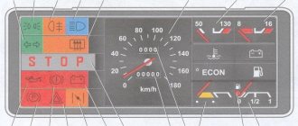
1. Thermistor; 2. Contact spring; 3. Cylinder head; 4. Paper insulating cartridge; 5. Sensor housing; 6. Sensor cover; 7. Frame with pointer coils; 8. Magnet for returning the needle to the beginning of the scale; 9. Thermal compensation resistor; 10. Permanent magnet; 11. Indicator lamp for external lighting; 12. Fog light indicator lamp; 13. Reserve warning lamp; 14. Indicator lamp for high beam headlights; 15. Rear window heating indicator lamp; 16. Speedometer; 17. Daily trip counter; 18. Coolant temperature gauge; 19. Voltmeter; 20. Fuel level indicator; 21. Fuel reserve indicator lamp; 22. Econometer; 23. Summing counter of the distance traveled; 24. Parking brake warning lamp; 25. Battery discharge warning lamp; 26. Brake fluid level warning lamp; 27. Carburetor air damper warning lamp; 28. Hazard warning lamp; 29. Oil pressure warning lamp; 30. Indicator lamp of the “Stop” display; 31. Direction indicator warning lamp; 32. Instrument cluster lighting lamp; 33. Socket for installing a relay-breaker for the parking brake warning lamp; 34. Level indicator and fuel reserve sensor; 35. Fuel reserve alarm contact; 36. Sensor rheostat; 37. Movable rheostat contact; 38. Lever with float; 39. Oil pressure sensor air filter; 40. Moving contact spring; 41. Movable contact of the sensor; 42. Fixed contact (connected to ground); 43. Diaphragm; 44. Brake fluid level sensor; 45. Wire ends to brake pad wear sensors; 46. Parking brake warning lamp switch; 47. Mounting block; 48. Instrument cluster; 49. Parking brake warning lamp relay; 50. I. Coolant temperature gauge; 51.II. Instrument cluster; 52.III. Connection diagram of the instrument cluster (reverse view); 53. IV. Fuel level indicator; 54. V. Oil pressure warning lamp; 55.VI. Scheme for switching on brake system warning lamps; 56.VII. The order of conditional numbering of plugs in the blocks of the instrument cluster.
All control devices and warning lamps of the car are combined into a single unit - instrument cluster type 22.3801. The instrument cluster combines a speedometer 16, an econometer 22, a voltmeter 19, a fuel level indicator 20 and a coolant temperature indicator 18. In addition, control lamps are located in a separate section on the left. Electrical connections between devices, control lamps and output plugs are made using the printed circuit board method on a foil-coated getinax board.
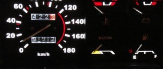
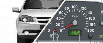
Speedometer 16 is attached to the instrument cluster housing with two screws. It has a dial speed indicator and two counters: summing 23 and daily 17 of the distance traveled, the readings of which can be set to zero using a handle located on the instrument panel. The speedometer mechanisms are driven by a flexible shaft from a drive mounted on the clutch housing. One revolution of the flexible shaft corresponds to 1 m of distance traveled.
An ecometer installed in the instrument cluster serves to roughly determine fuel consumption in a given engine operating mode. It is a vacuum gauge that measures the vacuum in the engine intake pipe, which is directly related to fuel consumption. The less open the throttle valves in the carburetor, the greater the vacuum in the intake pipe, and the less fuel consumption. And vice versa, with heavy loads on the engine, the throttle valves open almost completely, the vacuum drops (the econometer needle moves to the yellow zone of the scale), and fuel consumption increases.
The coolant temperature gauge works in conjunction with the TM-106 sensor. The mechanism of the device consists of a plastic detachable frame 7, on which coils are wound, and an axis with an arrow and a disk permanent magnet 10. In the rear half of the frame there is a small magnet 8, which returns the disk magnet with an arrow to the beginning of the scale.
The coils have three windings, one of which is wound perpendicular to the other two. Thus, there are three magnetic fluxes on the disk magnet, created by three windings. Depending on the resistance of the sensor, the magnitude of the current in the windings of the coils changes and therefore the direction and magnitude of the total magnetic flux acting on the disk magnet change. The poles of this magnet are located along the direction of the total magnetic flux and, accordingly, the arrow deviates at a certain angle.
If the sensor resistance is 640-1320 Ohms, the needle should be at the beginning of the scale, with a resistance of 77-89 Ohms - at the beginning of the red zone, and if the sensor resistance is 40-50 Ohms - it should deviate to the end of the red zone of the scale.
The TM-106 temperature indicator sensor is wrapped into the cylinder head on the rear side of the engine. The sensitive element in the sensor is thermistor 1, which changes its resistance as the temperature changes. The thermistor is pressed by a spring to the bottom of the housing, i.e. one side of it is connected to ground through the body. The other side is connected through a spring to a plug fixed in a plastic cover 6.
The fuel level indicator has the same structure as the temperature indicator. It differs in winding data, attachment points to the printed circuit board and the relative position of the disk magnet and the arrow. The indicator is used in conjunction with a sensor type 24.3827, which is installed in the fuel tank. This sensor also turns on the fuel reserve warning lamp 21 when there are 4-6.5 liters left in the tank. The sensor has a wire rheostat 36, along which contact 37 slides, controlled by a float. Depending on the fuel level, the float rises or falls and moves the movable contact of the rheostat, changing the resistance of the sensor. With a sensor resistance of 285-335 Ohms, the pointer needle should be at the beginning of the scale, with 100-135 Ohms - in the middle of the scale, and with 7-25 Ohms - at the end of the scale.
The voltmeter has the same principle of operation as the devices described above. With the ignition on and the engine not running, the voltmeter shows the voltage at the battery terminals, and after starting the engine, the voltage generated by the generator. If, when the engine is running, the needle is in the red zone at the beginning of the scale (8-11 V), then this indicates a discharge of the battery due to low tension of the generator drive belt or a malfunction of the generator itself. The red zone at the end of the scale corresponds to 15-16 V. If the arrow is in this zone, then the generator voltage regulator is faulty. The intermediate position of the arrow (between the red zones) indicates normal operation of the generator.
The oil pressure warning lamp 29 is turned on by a sensor of the MM-120 type, which is wrapped in the engine cylinder head on the side of the intake and exhaust pipelines. If the pressure in the lubrication system is below 0.2-0.6 kgf/cm2, then the movable contact 41 of the sensor is pressed by a spring to the stationary 42, the power circuit of the control lamp is closed, and the lamp lights up. As soon as the oil pressure exceeds 0.2-0.6 kgf/cm2, it bends the diaphragm 43 and, overcoming the resistance of the spring, pushes the moving contact away from the stationary one with a pusher. The power supply circuit for the control lamp opens and the lamp goes out.
Brake system warning lamps. The parking brake warning lamp 24 begins to “blink” when the switch 46 located under the parking brake lever is closed. In this case, current flows from plug “12” of the white block of the instrument cluster along two circuits. One circuit is closed to ground along the path: plug “12” of the white block - control lamp 24 - plug “L” of the breaker relay 49 and through closed contacts to the plug “+” - along a brown wire with a blue stripe to switch 46 and to "mass". Another circuit is closed to ground along the path: plug “12” of the white block - plug “-“, the winding of the breaker relay and through its closed contacts to the plug “+” - switch 46 - “ground”.
The current flowing through the winding of the breaker relay heats it up. The bimetallic plate of the relay-interrupter bends when heated, and the contacts of the relay-interrupter open. The current in both circuits is interrupted and lamp 24 goes out. The bimetallic plate cools down and takes its previous shape. The breaker relay contacts close again, turning on the warning lamp, and the described cycle is repeated with a frequency of 60-120 times per minute, causing the parking brake warning lamp to flash.
Since 1995, the parking brake warning lamp relay interrupter has not been used on cars and there are no plugs for connecting the interrupter relay. Now the conductors that were previously connected to the “+” and “L” plugs of the relay are short-circuited.
Simultaneously with control lamp 24, lamp 30 “Stop” also flashes, the current through which flows from plug “12” of the white block, through diodes to plug “3” of the white block, and then along brown wires with a blue stripe to switch 46 and to ground "
The brake fluid level warning lamp 26 is turned on by sensor 44 located in the reservoir of the main cylinder of the hydraulic brakes when the fluid level becomes the minimum permissible. In this case, the current flows through the circuit: plug “12” of the white block of the instrument cluster - lamp 26 - along pink wires with a blue stripe to sensor 44 - “ground”. At the same time, the 30 “Stop” lamp also lights up, the current through which flows in a parallel circuit through a diode
Low version dismantling procedure
A low dashboard is used in some VAZ-2109 cars, as well as in the Baltika modification. If the situation forced you to disassemble this part of the interior, then do the work like this:
- First of all, remove the 3 knobs from the panel for switching stove modes.
- Removing the airflow control knob is simple - slightly pull it towards you.
- On both sides of the shield, remove the fasteners of the decorative trim, then slide it towards you.
- Disconnect the connectors with wires from the fog lights and heated rear window switches. There is another wire going to the latter that needs to be disconnected.
- De-energize the hazard light switch and the cigarette lighter illumination.
- Now you can begin to remove the cigarette lighter wiring and decorative trim from the stove.
- On the stove control element you will see 4 fasteners that will need to be removed.
- Next, remove the 2 fasteners from the instrument panel.
- Remove the dashboard visor.
- Compress the spring clips and remove the housing from the instrument cluster.
- Unscrew the speedometer fastener and disconnect it from the drive cable.
- On the instrument panel, find the block with white wires and disconnect it from the power.
- Find the econometer fitting and remove the hose from it. After this you can remove the cotter pin.
- Then disconnect the speedometer from the cable, which is used to record the readings of the device for the day.
- Disconnect the red wire from the power supply.
- Pull the hydraulic corrector and light switch handles towards you.
- Unscrew the two fastening nuts that are located at the hydraulic corrector socket and next to the instrument backlight switch.
- Remove the steering wheel, along with the switches that are located under it.
- You can only remove the power pads from the ignition switch if you turn it to position 1 with the key.
- Remove 2 fasteners and the same number of nuts from the steering column.
- Remove the steering column along with the ignition switch.
- Pull the choke handle towards you to remove it from the rod. This rod is held in place by two fasteners that need to be removed.
- Remove the bolts from the left side and bottom of the instrument panel. Do the same on the right side.
- Inside the glove compartment there is another fastener that needs to be unscrewed.
- Remove the last fasteners and carefully remove the panel.
How to change the backlight of the VAZ 2109 panel
During a trip, an experienced driver carefully looks not only at the road, but also at the dashboard. This is necessary to monitor the corresponding readings of the sensors that are responsible for the operation of the vehicle. It should be noted that its illumination should not tire or strain the eyes.
The manufacturer equipped new cars with pale green or yellow backlighting. It has a certain effect on the eyes - after a certain period of time they get tired. In this situation, it is better to replace the factory instrument lighting. For such tuning you will need a set of diodes, a soldering iron, screwdrivers with attachments, gloves, and iron pliers. Then we need to choose the color of the backlight. There are many possible options, it all depends on your imagination.
However, as always in any work, this process has its own nuances. It is recommended to install a soft white backlight if you use the car every day or for long trips. It will not tire your eyes. However, if you rarely use the car, then it is better to install light bulbs of a different, most varied color. Now let's start the installation.
First you need to completely remove the dashboard and disassemble the dashboard. To do this, unscrew the screws holding the dashboard to the body. You can find out their number by studying the car's operating instructions. It is possible that you can remove the panel if you disconnect only the trim and release the steering column all the way down.
Then we need to unscrew the bolts that are located at the bottom of the trim. Using a screwdriver and a flat socket, pry up the instrument cluster and remove it. You should be especially careful because you can accidentally damage the glass. After that, unscrew the bolts on the back side. We disconnect the glass, and then the plastic gasket.
There is no need to touch the arrows; you should work carefully, because you can accidentally hit them or knock them down. If this happens, you will have to set them again and, what is even more difficult, adjust the sensors. When examining the back of the light bulb, you can see the location of all lighting fixtures, including LEDs.
We outline them with a marker and unsolder them from the microcircuit. We check new light elements with an adapter or battery. It is better to use LEDs because they will consume a small amount of energy and also have a long service life. Then you need to inspect the metal antennae of the diodes so that they are intact. Otherwise the diode will not light up. We insert both antennae of the diode into the hole in the microcircuit that remains after soldering the previous light bulbs. We solder the antennae on the back side of the circuit.
We mount the remaining diodes in the same way. Reassembly must be done in reverse order. Then we start the car and turn it on. Thus, we check how the installed LEDs function.
Despite all the ridicule of foreign skeptics, the history of the domestic automotive industry remembers many outstanding car models. Among the latter is the legendary car, a real people's favorite - the VAZ 2109. Many of our compatriots still successfully use this car, so it will be quite logical if we consider the most common methods of tuning the interior of this popular model.
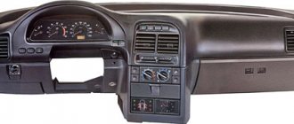
Instrument panel VAZ 2109 high panel
Description of the VAZ 2109 instrument panel (High panel): 1. Ignition switch, 2. Hazard warning switch, 3. Windshield wiper and washer switch lever, 4. Radio socket, 5. Central nozzles of the interior ventilation and heating system, 6. On-board computer ( installed as part of the package), 7. Instrument panel, 8. Glove box lid, 9. Side nozzles of the interior ventilation and heating system, 10. Loudspeaker trim, 11. Shelf, 12. Power window switches (installed as part of the package), 13. Cigarette lighter, 14 . Control panel for the interior ventilation and heating system, 15. Gear shift lever, 16. Parking brake lever, 17. Ashtray, 18. Carburetor choke handle, 19. Accelerator pedal, 20. Brake pedal, 21. Clutch pedal, 22. Horn switch, 23. Instrument lighting switch, 24. Hydraulic headlight leveler, 25. Front seat heating switch (installed as standard), 26. Rear fog lamp switch, 27. Fog lamp switch (installed as standard), 28. Heated glass switch tailgate, 29. Hood lock drive lever, 30. Turn signal and headlight switch lever, 31. External lighting switch, 32. Instrument cluster.
More information about the instrument cluster for the high panel (torpedo) VAZ 2109
1. Speedometer, 2. Trip counter reset handle, 3. Trip counter, 4. Total mileage counter, 5. Fuel level indicator, 6. On-board control system light panel, 7. “TEST” display, 8. “Test” display STOP”, 9. Indicator lamp for failure of brake lamps and side lights, 10. Indicator lamp for low brake fluid level, 11. Indicator lamp for low coolant level, 12. Indicator lamp for front brake pad wear, 13. Indicator lamp for low level level in the washer reservoir, 14. Indicator lamp for low oil level in the engine crankcase, 15. Coolant temperature indicator, 16. Tachometer, 17. Indicator lamp for engaging the parking brake, 18. Indicator lamp “CHECK ENGINE” system injection, 19. Indicator lamp for closing the carburetor air damper, 20. Indicator lamp for reserve fuel remaining, 21. Indicator lamp for emergency oil pressure in the engine lubrication system, 22. Indicator lamp for turning on the right turn indicators, 23. Indicator lamp for battery charge, 24. Left turn indicator warning light, 25. Seat belt warning light, 26. Doors not closed warning light, 27. Side lights warning light, 28. High beam headlight warning light, 29. “CHECK ENGINE” warning light. engine”) toxicity reduction systems.
Instrument panel VAZ-2108
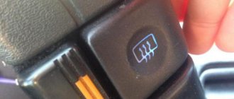
The instrument panel of the basic version of the G8 was popularly nicknamed “low” because of its appearance. It is a large shelf, the surface of which is located below the level of the windshield. Used in the VAZ-2108 until 1997. And then the panel was replaced with a “high” one for cars with index 21083.
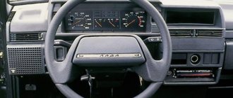
On the left half, the instrument panel of the VAZ-2108 rises above it. To the left of the steering wheel there are control handles for the hydraulic leveling of the headlights and the illumination of the instrument panel.
On both sides of the steering column there are combined control levers for electrical appliances. The left one is designed to turn on the turn signals, constant and short-term high beam headlights. The right one controls the windshield and rear window wipers, as well as the washer pump. Also on the right side is the ignition switch and the carburetor choke lever (choke handle).
Above the central tunnel are:
- heating system deflectors;
- control buttons for the main electrical equipment: side lights, low beam headlights, hazard warning lights, fog lights, heated rear window.
- heater control unit;
- space for a radio;
- cigarette lighter
The heating control unit includes:
- four-position fan switch;
- 2 handles that control the direction of air flow inside the panel (passenger and driver side);
- heater valve control lever.
On the right half of the VAZ-2108 instrument panel there is a glove box (glove compartment) with lighting inside and a small shelf under it.
Possible faults
What malfunctions are typical for the dashboards of VAZ cars? Check out the main list after watching a video about connecting the shield from a VAZ 2110 to a “nine” (the author of the video is Garage BFS).
- The speedometer does not work. There may be several reasons for this - a broken cable, its incorrect installation or wear of the socket. You should try disconnecting the cable and reconnecting it.
- The odometer, which records the mileage of the vehicle, does not work. This problem is usually resolved by replacing the device.
- One or another indicator does not light up. Perhaps the sensor itself has failed or the light bulb has burned out.
- The instrument panel backlight does not work. This is usually due to burnt out bulbs or bad contacts. There may also be problems in the electrical circuit, but this happens rarely.
- The coolant or oil level sensor is giving incorrect information. For example, the driver is warned about a lack of engine fluid level or boiling refrigerant in the expansion tank, but in fact, with these parameters everything is normal. The problem is usually solved by replacing the sensors.
Removing the car dashboard
- Using a Phillips screwdriver, remove the three screws that secure the center console;
- remove the cover, the protrusion located at the bottom, remove the protrusion from the bracket;
- Using a nozzle, unscrew the five screws located in the console on the right and remove the screen;
- Disconnect the terminal with the (-) sign from the battery. If there is a radio receiver, you need to remove it, remove the plug from the shield;
- Disconnect the wires coming from the cigarette lighter, remove the cartridge;
- Using a narrow screwdriver, remove the handle from the levers;
- pull the handle towards the heating and fan switch;
- unscrew the two screws above the panel and the two located under it using a screwdriver;
- unscrew the screw located behind the panel;
- Also unscrew the two self-tapping screws securing the cover;
- disconnect the harness and wire connectors. To avoid confusion when installing the panels, you should mark the order in which they are connected;
- unscrew the fastening bolts;
- unscrew the two self-tapping screws, those that secure the bottom bracket using an 8 key;
- unscrew the self-tapping screw securing the light guide and remove it;
- Also unscrew the screws securing the heating unit;
- remove lamp sockets;
- after removing the external parts, remove the decorative insert;
- unscrew all nuts with a 21 key;
- hydrocorrector, remove its lamp;
- Unscrew the screws that are attached to the cross member on the left.
- Finally, the panel itself is removed. The panel is assembled accordingly in the reverse order.
In general, the repair work is quite doable even with your own hands, but before starting dismantling work, you need at least a pinout mapped on paper, otherwise it will be difficult: you will need to “trace” every wire and every connection that is on the “path” from devices to the power button.
Basic faults
Like any other technical device, the VAZ-2108 instrument panel may break down or display information incorrectly. This happens for 3 reasons:
- The lamp or scale has failed.
- The electrical circuit between the indicator and the signal source is damaged: the tracks in the instrument cluster board are burned out, the wire/cable of the mechanical speedometer is broken, poor contact at the terminal connections due to dirt or oxidation, the fuse has melted.
- The signal source is damaged. For example, the float in the gas tank is stuck in the upper position. Then the fuel level scale will show that there is enough fuel.
To find out on your own why the panel instruments in the VAZ-2108 do not work, you will need a multimeter and repair and operating instructions. It contains instructions for checking each element of the circuit
Fuse box VAZ 2104 2105
Where is the VAZ fuse mounting block located: 2104, 2105 (carburetor, injector)
The mounting block is located in the engine compartment on the right side and is attached to the front panel. The mounting block is closed on top with a lid on which symbols for the purpose of the relay, fuse numbers and the circuits they protect are printed. Most of the vehicle's electrical circuits are protected by fuses installed in the mounting block.
| F1 | 10 | Tail lights (reversing lights). Heater motor Warning lamp and rear window heating relay (winding) |
| F2 | 10 | Electric motors for the windshield wiper and washer pump. Windshield wiper relay |
| F3 | 10 | Spare |
| F4 | 10 | Spare |
| F5 | 20 | Rear window heating element and heating relay (contacts) |
| F6 | 10 | Cigarette lighter. Portable lamp socket |
| F7 | 20 | Sound signals and relay for turning on sound signals. Engine cooling fan motor and motor switch relay (contacts) |
| F8 | 10 | Direction indicators in hazard warning mode. Switch and relay-interrupter for direction indicators and hazard warning lights in emergency mode |
| F9 | 7.5 | Generator voltage regulator (on vehicles with G-222 generator) |
| F10 | 10 | Turn indicators in turn signal mode and corresponding indicator lamp. Turn signal interrupter relay. Turn signal indicator Tachometer Fuel level indicator. Coolant temperature gauge. Voltmeter. Fan motor activation relay (winding). Battery charge indicator lamp. Indicator lamps for fuel reserve and parking brake activation. Warning lamps for emergency drop in oil pressure and insufficient brake fluid level. Indicator lamp for turning on the parking brake. Indicator lamp for covering the carburetor air damper (for a carburetor engine). Electric fan thermal switch. Carburetor pneumatic valve control system Generator excitation winding (generator 37.3701) |
| F11 | 10 | Rear lights (brake lamps). Body interior light |
| F12 | 10 | Right headlight (high beam). Winding of the relay for turning on the headlight cleaners (with the high beams on) |
| F13 | 10 | Left headlight (high beam). Indicator lamp for high beam headlights |
| F14 | 10 | Left headlight (side light). Right rear light (side light). License plate lights. Engine compartment lamp Indicator lamp for turning on side lights |
| F15 | 10 | Right headlight (side light). Left rear light (side light). Cigarette lighter lamp. Instrument lighting lamp. Glove compartment lamp |
| F16 | 10 | Right headlight (low beam). Winding of the relay for turning on the headlight cleaners (with the low beam on) |
| F17 | 10 | Left headlight (low beam) |
Connection diagram of the mounting block:
P1 — relay for turning on the heated rear window; P2 - relay for turning on headlight cleaners and washers; PЗ - relay for turning on sound signals; P4 - relay for switching on the electric motor of the engine cooling system fan; P5 - headlight high beam relay; P6 — headlight low beam relay; A - the order of conditional numbering of plugs in the mounting block blocks. The outer number with the letter “Ш” in the plug designation is the block number, and the inner number is the conventional number of the plug. The plugs of the blocks without color marking are conventionally shown in brown
Location of relays and fuses in the mounting block: 1 - relay for turning on the heated rear window; 2 — place for installing a relay for turning on headlight cleaners and washers (the relay is installed on some manufactured cars); 3 — mounting jumper in place of the relay for turning on sound signals (in a variant, a relay is installed); 4 — mounting jumper in place of the relay for turning on the electric motor of the cooling system fan (in a variant version, a relay is installed); 5 — relay for turning on the high beam headlights; 6 — relay for turning on low beam headlights;
F1-F17 - fuses (circuits protected by pin-type fuses are indicated in the table above).
Electrical equipment that consumes high current during operation is connected through relays that protect switch contacts from overload. To replace pin fuses and relays, special plastic tweezers are provided in the mounting block.
Fuses of different ratings are painted in different colors; In addition, the fuse is marked with a numerical value of the current for which it is designed (rated value).
The color of the fuse body and its correspondence to the rating 20A - Yellow 15A - Blue 10A - Red
7.5A - Brown
Installation on VAZ 2108 and 2109 with a low torpedo instrument cluster from 2115
Having once read an article on one of the sites about replacing the instrument cluster (hereinafter referred to as KP) of a VAZ 21083 with a “high” panel with a combination with 2110, I decided to do the same in the version with a “low” panel. I also found a description of the alteration itself. At first glance, everything seemed as simple as shelling pears, however, having taken it seriously, it turned out that the 2115 dlski does not fit into the visor of the standard instrument panel, although it coincides exactly in dimensions with the 2110.
Minuses:
- no suitable visor! You either need to do it yourself, or buy a decorative plastic overlay for the 'low' panel and then adjust everything to it, as I did;
- you need to cut the front panel itself in order to “sink” the gearbox into it and put the trim on top, because the cover was intended for the standard 2108 gearbox, it also needs to be trimmed and bent, and fiddling with plastic is quite a troublesome task.
- There will no longer be such useful instruments as a voltmeter and an econometer.
Pros:
- built-in clock with LCD indicator;
- built-in LCD outdoor temperature indicator with ice warning function;
- well, a very nice backlight that cannot be compared with the standard 2108,
- there is a tachometer, and the movement of all the needles is smooth, without jerking (thanks to the stepper motors used)
By the way, in addition to the 2115 gearbox itself, you also need to acquire a speed sensor. There are three varieties: 1. GM (with an American standard round plug), 2. domestic with a plastic shaft, 3. domestic with a metal shaft.
You should take only the third type, because the plastic shaft softens from the heat of the gearbox and flies very quickly, and for GM it is difficult (and most importantly expensive) to buy a mating part of the connector. Don't forget to look for the inscription '6 imp/revolution', because... The sensor for the trip computer looks exactly the same, but gives 10 pulses per revolution. If you want to implement the function of measuring the outside air temperature, you also need a temperature sensor. I recommend the VDO sensor, it has the smallest error. There must be a block with wires with it!
Step one: redo the electrical
Using a small screwdriver, remove the terminals from the blocks leading to the dashboard and shuffle them according to the following table.
| Combination 2108 | The wire | Chain | Combination 2115 | ||
| Block | Terminal | Block | Terminal | ||
| red | 9 | TO | Counter. side light lamp | white | 6 |
| red | 1 | AF | Counter. high beam lamp | red | 11 |
| white | 7 | GP | Counter. fuel level lamp | — | — |
| red | 6 | RG | Counter. brake level lamp liquids* | red | 7 |
| red | 7 | KG | Counter. parking brake lamp | white | 11 |
| red | 13 | KB | Counter. battery charge lamp | white | 12 |
| red | 5 | SG | Counter. oil pressure lamp | white | 13 |
| red | 11 | GB | Counter. emergency lamp alarm | red | 12 |
| red | 12 | JV | Counter. choke opening lamp | white | 7 |
| red | 4 | GP | Counter. turn signal lamp | — | — |
| ** | ** | MS | - // - left | red | 5 |
| ** | ** | G | - // - right | red | 6 |
| red | 2 | Salary | Counter. glass heating lamp | *** | *** |
| red | 8 | VERY | Counter. fog lamp Sveta | *** | *** |
| white | 4 | B | Instrument lighting**** | red | 4 |
| ***** | OZ | Tachometer input high voltage | white | 3 | |
| ***** | WITH | Speed sensor | red | 9 | |
| white | 2 | ZB | Coolant temperature sensor | white | 5 |
| white | 13 | RP | Fuel gauge input | red | 10 |
| white | 12 | ABOUT | +12V | white | 10 |
| white | 9 | OG | +12V | red | 2 |
| white | 8 | BW | Ground, input 2 temperature sensors | red | 3 |
| red | 10 | H | Weight | white | 1 |
| white | 5 | H | |||
| — | — | — | temperature sensor input 1 | red | 1 |
| — | — | — | const 12 V (from terminal 30 of the ignition switch) | white | 4 |
Notes *- it is necessary to connect +12V to the brake fluid level sensor instead of ground (black wire), for example, from pin 4 (blue-red wire) of the switch or from pin 4 (also blue-red) of the EPHH control unit **- diverted from the corresponding terminal of the hazard warning switch in the console ***- The wire is carefully released from the harness and inserted back into the console, where it is connected to the corresponding warning lamp in the switch housing. Or it is carefully wrapped with electrical tape, and the wiring from the switch itself is routed to the indicator lamp. For more details, see below **** - in order for the instrument lighting to turn on when the ignition is turned on, I have a “plus” applied to the “positive” contact of the instrument illumination brightness adjustment resistor from terminal 15/2 of the ignition switch, the old contact is insulated.
Next, a ***** harness of four wires is knitted - gray, blue and purple, black and orange-green. Black (ground) goes from terminal 3 of the speed sensor connector to terminal 3 of the red combination block. Blue with purple (+12V) - from terminal 15/2 of the ignition switch to terminal 1 of the speed sensor. Gray (speed sensor output) - from terminal 2 of the sensor to terminal 9 of the red combination block. And finally, the orange/green goes from the ignition coil 'K' terminal to terminal 3 of the white combination block. The harness is passed in place of the speedometer cable and is sealed with a rubber passage plug. The econometer tube is unscrewed from the manifold along with the fitting and the hole is plugged with a copper bolt.
Step two: implanting the dashboard into the panel
Having made sure that it wouldn’t fit into the window from the old gearbox, I had to take a hacksaw and slowly expand the window on the right and left. It was immediately discovered that under the layer of polyurethane foam that covered the panel, there was also a sheet of metal, which probably should give the panel rigidity. Carefully expanding the panel window, we leave small “ears” made of this metal so that later, bending them as required, drilling holes in them and securing the gearbox with self-tapping screws through the side holes. I expanded it like this: I used a hacksaw blade to make small horizontal slits in the corners of the panel window and several additional slits, not forgetting about the lugs for future fastening. Then, with the effort of his hands, he tried to bend the resulting fragments down. I broke out the excess. The window also had to be expanded from above to ensure an acceptable tilt of the gearbox. We don't touch anything at the bottom. I also had to cut off the upper lugs of the gearbox, which interfered with the normal installation of the lining.
Step three: installing decorative trim
You need to recess the gearbox into the panel so that the cover can sit on top of it normally. I strongly do not recommend using covers made of fiberglass. They cannot be bent using heat. Fiberglass does not melt even in a fire, and it is difficult to cut. We cut out the upper part of the lining according to the shape of the gearbox glass, the lower and side parts should be brought out under heating so that with subsequent trimming the shape of the gearbox glass is obtained. Under heating, we try to move them as far as possible in opposite directions in order to expand the window of the lining. The plastic was heated using a Chinese gas burner (a tiny blowtorch), which provided good spot(!) heating. We do not recommend heating over a gas stove, because... plastic will 'float' everywhere. Having stopped heating, we immediately try to “bend” the walls inward with our fingers, thereby expanding the window. Any excess that interferes with fitting is immediately trimmed with a blade. The situation was worse with the lower left and right corners. They are important because lamps indicating external lighting and suction could be hidden behind them. I warmed more of the side of the corner, and not the bottom, because otherwise the lower part of the pad will 'float'. There were some minor mistakes; I tried to correct the inaccuracies in the reverse order. Next we paint the entire trim with matte black paint. To hide the defects in trimming the trim, I placed a seal from the rear light of a VAZ 2105/2107 around the perimeter of the cut window. The trim is attached with self-tapping screws from the ends of the panel, and the front part of the trim is secured with double-sided tape. As practice shows, this is enough. You can also screw the front part with self-tapping screws and paint their heads black, but, to put it mildly, this will not add any special aesthetics.
I indicate the operation of fog lights, flashlights and rear window heating in the following way: we replace all these buttons with similar ones, but with internal illumination, and not with light bulbs, with LEDs of the required size and color with a 2 kOhm resistor, and remove the green filter. We do the same with the outdoor lighting switch, replacing the light bulb with an LED. Small printed circuit boards with soldered current-limiting resistors and red LEDs are installed in the places provided in the console next to the buttons so that the light from the desired LED falls directly on the light guide ('eye') of the desired button. The switching wires are connected through the connector to the contacts in the block of the desired button, to which + 12V is supplied after switching on.
Dismantling stages
There is a story among “Kulibin” motorists that only a professional, after dismantling and repairing, can put everything back together. In this case, unnecessary parts will remain and everything will work better than before.
This is the result that those who want to replace the instrument panel themselves strive for. There are no particular difficulties in this process, and since all types of panels for a given brand of car are dismantled almost the same way, let’s look at how to remove the dashboard on a VAZ with a low platform.
- Disconnect the battery.
- Set the wheels straight, disconnect the carburetor choke drive rod, and also disconnect the speedometer from the transmission.
- By pulling towards yourself, remove the three interior heating control knobs, as well as the blower mode switching knob.
- On the passenger seat side, disconnect the shield where the instrument panel trim is located, and remove the lower part of the solid panel block.
- Carefully disconnect all connections that are attached to this element.
- The next important step is to unscrew the four screws securing the stove control panel. This step is often skipped, which can later cause the part to break due to sudden pulling.
- Unscrew the screws that are located directly at the top of the niche.
- Remove the housing covering the niche, compress the spring clips on the sides of the glass, blocking access to the scales. Remove the housing and disconnect the speedometer cable.
- Carefully disconnect all wires and mechanisms suitable for this instrument unit.
- Remove all light knobs.
- Remove the steering wheel and related mechanisms.
- The VAZ torpedo is equipped with an anti-theft system that blocks the steering mechanism. Therefore, you need to insert the ignition key to position “0” to unlock the anti-theft system. Only then can the ignition switch be turned off.
- Disconnect the steering column and remove the pipe along with the lock.
- Remove the handle and unscrew the choke rod guide.
- Unscrew the screws located on the left and right (almost at the door itself) that secure the VAZ dashboard on the sides.
- Unscrew the screws located in the glove compartment, as well as near the gas pedal and on the passenger side.
Peculiarities
Most of all, “chisels” liked the “low” panel due to one significant difference from the “high” one - the well-designed arrangement of air ducts. In 21083, the air forced by the fan from the heater core is lost somewhere inside it. As a result, the interior does not warm up well.
The second feature is the low quality of plastic and poor fit to body parts. At the slightest vibration or pressure, it begins to creak unpleasantly. And when driving on uneven roads, the noise from it is similar to a baby rattle.
Instrument panels with indexes 2108 and 21083 were installed on the first generation of front-wheel drive models; in addition to the cuts, they differ from each other only in the location of the equipment control buttons and differently combined control devices.
Instrument panel VAZ-2114 (European panel)
This part was installed only in the VAZ 21099-40 of the last years of production (2000-2002) and the second generation of Lada-Samara: 2113, 2114, 2115. But thanks to the identical interior dimensions and the 2111 engine, this panel can be easily installed in fuel-injected V8s " and "nines".
Panel 2114 has a smoother and more rounded shape compared to 21083. Lighting control buttons are located above the compartment for the on-board computer to the right of the driver. An additional glove compartment compartment has been added: it opens from inside the main one.
Diagram of the instrument cluster of a “high” panel with an on-board control system
The instrument clusters of the “high” panel and the “European panel” are equipped with an on-board control system.
This combination of instruments includes: a speedometer with daily and total distance meters, a coolant temperature indicator, a fuel level indicator, a tachometer, 13 warning lamps and an on-board control system (OBS) unit. Diagram of the VAZ 2109 instrument cluster with a “high” panel with an on-board control system (manufactured before 1996): 1 - relay-breaker for the parking brake warning lamp 2 - tachometer with voltage stabilizer 3 - instrument cluster lighting lamp 4 - temperature indicator 5 - block controls BSK 6 - fuel level indicator 7 - resistor 50 Ohm, 5 W 8 - indicator lamp "CHECK ENGINE" for the toxicity reduction system 9 - indicator lamp for high beam headlights 10 - indicator lamp for side lights 11 - reserve indicator lamp 12 - indicator lamp not seat belts fastened 13 — left turn signal indicator light 14 — resistor 470 Ohm, 0.25 W 15 — electronic voltmeter 16 — right turn indicator light indicator 17 — emergency oil pressure indicator light 18 — fuel reserve indicator light 19 — air damper indicator light carburetor 20 — “CHECK ENGINE” warning light for the fuel injection system 21 — parking brake warning light Diagram of the VAZ 2109 instrument cluster with a “high” panel with an on-board control system (manufactured after 1996):
1 - tachometer 2 - instrument cluster illumination lamp 3 - temperature indicator 4 - BSK control unit 5 - fuel level indicator 6 - "CHECK ENGINE" indicator lamp for the emission reduction system 7 - headlight high beam indicator lamp 8 - side light indicator lamp 9 - reserve warning light 10 — warning light for unfastened seat belts 11 — left turn signal warning light 12 — battery charge warning light 13 — right turn indicator warning light 14 — emergency oil pressure warning light 15 — fuel reserve warning light 16 — air pressure warning light carburetor flaps 17 — “CHECK ENGINE” warning light for the fuel injection system 18 — parking brake warning light B1 — 91 kOhm resistor B2 — 50 Ohm resistor, 5 W Pinout of connectors for the VAZ 2109 instrument cluster with on-board control system
| Plug no. | Address (purpose) of the plug |
| White connector | |
| 1 2 3 4 5 6 7 8 9 10 11 12 13 | Reserved output Reserved output To the seat belt relay Fuse “5” for instrument protection (“+” for the direction indicator and hazard warning relay relay — — To fuse “7” for the protection of interior and exterior lighting lamps To fuse “14” for the left high beam protection headlights Reserve terminal To the fuel level sensor (terminal for the fuel level indicator) To terminal “61” of the generator To the temperature indicator sensor |
| Red connector | |
| 1 2 3 4 5 6 7 8 9 10 11 12 13 | — Fuse “5” for instrument protection (“+” for powering instruments) To terminal “K” of the ignition coil To the instrument lighting switch To the fuel injection system control unit — To “ground” To the parking brake switch Reserve terminal To the carburetor choke warning lamp switch To the fuel level sensor (terminal for the fuel reserve warning lamp) To the oil pressure warning lamp sensor To terminal “49aR” of the turn signal and hazard warning lamp relay |
| 9-terminal connector (for BSK) | |
| 1 2 3 4 5 6 7 8 9 | Fuse “5” for instrument protection (“+” power supply) To terminal “50” of the ignition switch To “ground” To the washer fluid level sensor To the oil level sensor To the coolant level sensor To the brake fluid level sensor To the brake lining wear sensors To terminal “ 3" lamp health monitoring relay |
Instrument cluster VAZ-2108
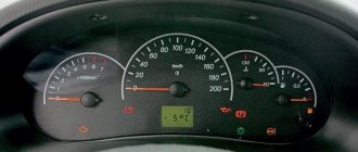
The instrument panel of the VAZ-2108 (low panel) is a combination of the following indicators:
- speedometer;
- mileage counters: daily and total;
- voltmeter, econometer, thermometer;
- fuel level.
In addition to indicators in the instrument cluster there is a set of lamps that indicate:
- insufficient battery charge;
- lack of pressure in the oil supply system;
- carburetor choke position;
- current amount of brake fluid and brake pad wear;
- direction of rotation and activation of the hazard warning lights;
- condition of the parking brake (handbrake);
- state of external lighting (side lights, low beam, high beam or fog lights are on).
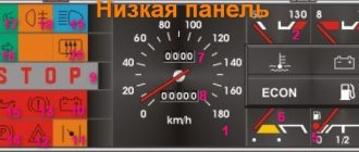
Devices 2108 (low panel) allow you to carry out basic diagnostics: brakes, coolant, headlights and taillights. If any element is faulty, its lamp will light up red and the word “STOP” will appear. This indication is advisory in nature and does not prevent the engine from starting.
What has changed in the new dashboard of Lada Vesta
It is known that cars going for export will be the first to receive the update, however, the Russian market should also be replenished with such versions of Vesta in 2022.
In the front part, the changes affected the following:
- font increased;
- daytime instrument lighting appeared;
- The scale backlight color turned orange.
In theory, changing the instrument lighting will correct problems with reading readings. In the photo of the Lada Vesta instrument panel you can see that it has become much more presentable.
The new instrument panel is illuminated at the proper level at night and during the day.
There are also several useful functionality improvements:
- added voice accompaniment;
- the volume of sound signals has increased;
- the time is now automatically synchronized with the satellite (the driver only needs to set the time zone);
- “Unfastened passenger seat belts” and “Low tire pressure” indicators appeared.
It is still unknown whether backlight brightness adjustment will be implemented.
High instrument panel
According to the diagram presented below, the VAZ 2109 with a high panel has the following components.
| Item number | What is this |
| 1. | Ignition switch |
| 2. | Hazard switch |
| 3. | Windshield wiper and washer control lever |
| 4. | Radio socket |
| 5. | Central nozzles of the interior heating and ventilation system |
| 6. | On-board computer (not available on all trim levels) |
| 7. | Dashboard |
| 8. | Glove compartment lid (glove compartment) |
| 9. | Side nozzles of the interior heating and ventilation system |
| 10. | Speaker (loudspeaker) trim |
| 11. | Shelf |
| 12. | Power window switches (available on certain trim levels) |
| 13. | Cigarette lighter |
| 14. | Control panel for heating and interior ventilation system |
| 15. | Gearbox shift lever |
| 16. | Hand brake lever |
| 17. | Ashtray |
| 18. | Carburetor choke handle |
| 19. | Gas pedal |
| 20. | Brake pedal |
| 21. | Clutch |
| 22. | Horn switch (horn) |
| 23. | Instrument panel light switch |
| 24. | Headlight hydrocorrector |
| 25. | Front seat heating switch (available as standard) |
| 26. | Rear fog light switch |
| 27. | Front fog lamp switch (not available on all trim levels) |
| 28. | Rear defogger switch |
| 29. | Hood lock drive lever |
| 30. | Turn signal and light control lever |
| 31. | Outdoor optics switch |
| 32. | Instrument cluster |
In order to eliminate certain malfunctions, monitor the operating parameters of the engine and vehicle systems, it is necessary to learn how the instrument cluster with a high panel is designed when you first get acquainted with the VAZ 2109.
Dashboard upgrade
Some car enthusiasts do not like the gray serial instrument panel of the VAZ-2108. Therefore, they strive to make it better and more unique. Many tuning methods have been invented: simple and cheap, expensive and complex.
Method No. 1. Repaint removable panel elements using spray paint: instrument cluster surrounds, heating deflectors, glove compartment lid.
Method No. 2. Cover the front part of the dashboard with stickers. It is not recommended to stick them on the top of the panel, as the stickers are glossy and reflect in the windshield. This makes it difficult to keep your eyes on the road.
Method No. 3. Install an overlay on the instrument panel of the VAZ-2108. Plastic overlays for the dashboard are available for sale, imitating wood or export equipment of the car. It is also possible to install a Euro panel with minor modifications.
Method No. 4. Installing a tablet computer in the central part of the panel instead of the on-board computer and radio. It will add the function of a GPS navigator and multimedia center to the car.
Dashboard of a VAZ-21083 car
In the early 90s, the interior of front-wheel drive models was completely redesigned and the main change was a new “high” instrument panel with index 21083. It was unsuccessfully copied from the Volkswagen Golf 2 and was installed in cars 21083, 21093, 21099 until 2002-2003. Compared to the instrument panel of the VAZ-2108, the 21083 was more bulky and angular, and some controls were moved. For example:
- The headlight and hazard warning buttons are located on the edges of the instrument cluster.
- The buttons for heating the rear window and fog lights are located to the left of the steering wheel, next to the hydraulic corrector handle.
Space was also added for the on-board computer and power window switches in the central part of the panel. In cars equipped with an injector, the engine control unit is attached to the back of the shelf under the glove compartment.