Technical characteristics of the radio
Kalina's standard audio system
Technical characteristics of the standard radio in the Kalina “Lux” configuration:
- 2DIN touch screen;
- presence of stereophonic radio;
- ability to play multimedia files;
- ability to synchronize with a cell phone;
- work with bluetooth.
It is also good that cars with radios have passed all special tests before being released to the masses. They were tested at extremely low and extremely high temperatures, electromagnetic compatibility was checked with modeling of the radio interference spectrum.
Audio preparation in the “Norma” package
In this configuration, the option may be called differently:
- Audio system (FM, USB, SD card, Bluetooth, Handsfree), 4 speakers, external antenna
- Audio preparation (cable, external antenna, 4 speakers)
In other words, the “Norma” package is further divided into a number of design options. Four speakers will be installed in the front and rear doors in any case, but the radio will only be available in some versions of this configuration.
The standard speakers for Lada Kalina 2 have a catalog number: front - 2170-7901020 and rear - 2170-7901030. See also the review of the Lada Kalina 2 “Norma” radio.
Rules for choosing an audio system
Before you begin installing the radio on Kalina, you should select it at a car dealership or hardware store. The choice should be approached carefully and carefully. And before going to the store, it is better to decide on your desires and capabilities.
When choosing a radio for your car, you should decide which music media will be used as the main one. This will help you save some money. If, for example, a car owner is sure that he will not need a CD or cassette player, then why should he overpay for a radio with these functions.
Pioneer model range
When choosing a car radio, you should pay attention to the power ratings. They have a maximum and minimum threshold. Maximum power is rarely used, except in extreme situations. The choice should be made according to the rated power, that is, the one that is used most often. Manufacturers often indicate only maximum values on packages, so when choosing, you need to carefully study the instructions (passport), and not the box.
It is also worth paying attention to the control panel. It should be extremely simple and convenient, since it will most often be used while moving. Intricate designs can distract from the road. Convenient and understandable buttons and adjustable backlight brightness will only be beneficial. It is imperative to check the range of perceived frequencies. Since radio stations mainly broadcast in the range from 80 to 110 MHz, it is better that the tuner also has this range.
Pay attention to the number of outputs to the speakers and the resonant frequency, it should be lower.
How to install a car radio
Installation of a car radio is most often carried out in a standard place on the front panel of the car. Otherwise, installation of the radio is done using a special mount that you can make yourself. Since 1 DIN radios are the most common, the seats have a height suitable for installing these devices. For 2 DIN sizes, additional modifications to the dashboard will be required to install a player in the car.
You should check the package contents of the device before installing the car radio to make sure you have all the necessary parts. Installation of the standard radio is done using a special frame that is included with the device. It is used to fix the radio in the car. First, the box for small items is removed, which is located in the standard place for installation. Then the metal frame is inserted.
Using the supplied special tool, pick up and bend the fixing tabs.
The next stage of installing a car radio with your own hands is securing it to the seat. Some devices have a threaded hole on the back wall. A pin is screwed into it, with which you can further secure the player. To do this, attach a special strip to the back of the dashboard.
To install a non-standard radio, you will need to check which mount is used and whether it fits the seat. If there are threaded holes on the side walls of the device, then installation of the radio on the car is carried out by screwing it to the dashboard with bolts.
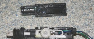
Stages of dismantling the Kalina radio
Car owners do not always install a radio in an empty place. Often, before installing a new audio system, you have to dismantle the standard one. Many drivers are not satisfied with its quality and characteristics. In addition, according to reviews from car owners, the standard radio very quickly begins to “freeze”, “slow down” and “glitch”. That is why the owner of a Lada Kalina car first has to remove the existing audio system, and only then install a new one, chosen independently.
Stages of removing the original Kalina radio:
- dismantle the top removable panel;
- remove the plastic frame;
- using the keys included with the standard radio, remove the system from the tunnel: insert the keys into the sides of the radio and pull it towards you;
- disconnect the connectors with wires and the antenna.
You can install the radio with the help of specialists in a specialized center. But it’s realistic to do everything yourself, because there’s nothing complicated about it. The procedure takes no more than two hours, it all depends on skill and experience.
Car enthusiasts can give their stock radio another chance by tuning it. Reflashing the software settings will make the interface more convenient, the performance and service life of the device will increase.
Audio preparation in the “Lux” package
The maximum configuration of Lada Kalina 2 has the option “Multimedia system (7″ display with TouchScreen, FM, USB, SD card, Bluetooth, Handsfree), 4 speakers, external antenna.” Nothing is required from the owner, everything is already there. See also the review of the Lada Kalina 2 Lux radio.
Let’s add that owners of Lada Kalina 2 “Lux” cars can flash MMS.
Nuances of installing an audio system
Dismantling of the standard audio system is completed
Without knowing all the intricacies of connecting the radio, it will be impossible to carry out the installation correctly, as a result this will lead to rapid discharge of the battery.
Connect the radio in parallel sequence with the red and yellow wires. This connection allows the system to be turned on and off only using a button on the panel of the device itself. Sometimes the radio circuit is specially designed so that the amplifier is powered in standby mode. Such a system consumes more energy, so the battery drains quickly.
What is the correct installation of a radio? To begin with, you should highlight 4 main wires, each of which has its own color and performs a specific function. The black wire goes to ground, the yellow one provides power to the memory and the audio system itself, the red one provides a signal to turn on the MMC, and the blue one turns on the antenna and other possible devices.
Before connecting, professionals recommend assembling a simple circuit that will allow you to connect the radio through the ignition, due to which the battery will be charged much longer. When working with wires and circuits, you will need to pinout the connector. This will make the circuit easier to work with and understand.
The circuit is assembled in the following order:
Before connecting the circuit, you will have to remove the radio and the slide; it is not necessary to remove the console.
All wires must be connected in the correct order:
- wire No. 1 is connected to the contact from the rear window heating button;
- The 2nd wire is connected to the multimedia system;
- wire No. 3 is soldered to blue, which is responsible for turning on the antenna;
- The 4th wire is soldered to the blue antenna wire.
The previously assembled board can be secured inside the torpedo with a fixed tie. When connecting all contacts, only the soldering method, insulated with heat shrink, is used. Screwing of wires is excluded. Before starting work, be sure to disconnect the battery.
With this connection, the radio will turn on only when the ignition is turned on, but if it is turned off, it will continue to work until the driver turns it off. Restarting is possible when the car is started again.
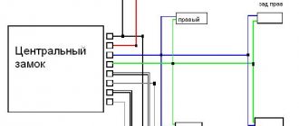
Marking of wires and their connection diagram
Almost all car radio manufacturers adhere to the same standard for marking input wires:
- BAT/B+ – yellow wire to the permanent positive of the battery. When connecting, a 10-20A fuse is used;
- ACC/A+ – red wire to the ignition switch terminal;
- GROUND/GND – black wire indicating minus or ground;
- REM - blue or white-blue control wire, responsible for turning on the car amplifier or antenna;
- ILL – orange wire to the light switch terminal;
- MUTE is a yellow-black wire responsible for remote muting or completely turning off the sound. If it is not included in the kit, then there is no need to buy such a wire.
There is another connection scheme when the red wire is connected together with the red one. This allows the audio system to operate regardless of whether the ignition key is turned on or off. The only disadvantage of such a scheme is that the tape recorder will always be in standby mode, which has a detrimental effect on battery performance. Its discharge rate can increase significantly.
For the radio output, the following wires are used, going to the speakers. They always come in pairs:
- FL- and FL + – minus and plus of the rear speaker (white wires);
- FR- and FR+ – minus and plus of the front speaker (gray wires);
- RL- and RL+ – minus and plus of the left rear speaker (green wires);
- RR- and RR+ – minus and plus of the right rear speaker (purple wires).
In each pair, one wire will be plain, and the second will have a black stripe. Striped means minus. Carefully read the color scheme of your radio and follow the sequence of wires.
Second installation option
There is another way to connect the radio, which will ensure that it is turned on not through the ignition switch, but using a separate button.
Mounting blocks for installing an audio system
If the wires of the block turn out to be short (and this often happens), it is better to extend them in advance by soldering. Twisting is not suitable here and should not be used.
The button is connected in the following way:
Cut the wire that fits the contacts of the red wire of the radio and solder wires 1 and 2 into the cut. A and B should be connected to the same contacts from the rear window heating button or other similar buttons. Do not forget that during all electrical work the battery should be disconnected.
If, out of habit, the radio was turned off with its original button, this is not a problem, because the indicator of the new button will still light up and remind you of the need to turn it off.
For those who have already installed radios on other Lada family cars, installing a multimedia device on Kalina will be a breeze.
And so, I wrote here >> Pioneer MVH-190UBG or looking for the second plus from the ignition switch once about how I connected the radio through the ignition switch. After a while I realized it was inconvenient. Sometimes you want to stand in nature and listen to music without an engine. Buy left button
and I didn’t want to hit a torpedo somewhere. Since I have a Kalinka Norma configuration, I decided to use the recesses with plugs that were not used for additional buttons and did this... I bought a button for turning on the heated windshield costing 180 rubles + a chip of 50 rubles:
She is without fixation and I realized it when it was already too late 
I had to buy an additional button to turn on the air conditioner (it has a lock) for 95 rubles:
Why did you take this one? Because the buttons on the Kalina center console have the same design. The only difference is in the number of backlight diodes, fixed or not, and the “heads” indicating the function for which this button is intended. So I just took the button, changed the “head” and that’s it, now my windshield heating button is locked. I made the connection like this:
The only thing is that I took the “+” from the instrument lighting from the emergency lights. It also lights up when you turn on the dimensions. This is not to go far UPD: From the factory, there is a white wire in one bundle of power and speaker wires for the radio. Usually it is folded back and hangs just like that. This wire is taken from the instrument lighting on which a “+” also appears when the dimensions are turned on and vice versa according to the electrical diagram. So don’t mess with the emergency lights and get the button illumination from the white wire, that’s what it’s designed for.
Here's what happened:
PS: The button is not confusing)
Connecting speakers
The process of connecting speakers requires special attention, so be sure to check the instructions. Usually there are plus and minus markings on the speaker terminals. Most often, the wide terminal is positive, and the narrow terminal is negative. If your car does not have such markings, use the simplest tester - a battery. Connect its + and – to the speaker terminals and if the cone moves outward, then you have determined the phasing correctly.
There is another way to determine phasing. To do this, transfer all audio to one of the front speakers and increase the volume to maximum until there is noticeable sound distortion. Balance the sound by evenly distributing the volume between the left and right speakers. If the phasing is done correctly, the overall volume will increase noticeably. If the sound does not become louder or the changes are barely noticeable, this indicates incorrect phasing and the need to swap the wires on one of the speakers. You can also check the rear speakers in the same way.
Important! Be sure to carry out a test, since if you connect incorrectly, you risk losing up to 80% of the sound quality or completely destroying the radio over time.
If your radio has low power, then it will only be equipped with positive wires for each speaker. In this case, the minus of the speakers is connected to the common minus of the audio installation.
You will know that the radio is connected incorrectly or in an “undesirable” way by the following signs:
- when parked, the battery will discharge very quickly, to such a state that it will be impossible to start the car;
- while listening to music, you will notice that the tape recorder constantly “stutters”, and when the volume increases, the car radio “turns off by itself”;
- When the power is turned off, all settings disappear.
If you notice such problems, it is better to check that all wires are connected correctly.
radio interference audio system selection
Before you begin installing the radio on Kalina, you should select it at a car dealership or hardware store. The choice should be approached carefully and carefully. And before going to the store, it’s better to decide on your own desires and capabilities.
When choosing a radio in the car, you should decide which music media will be used as the main one. This will help you save some money. If, for example, a car owner is sure that a CD or cassette player will not be useful to him, then why should he overpay for a radio with these functions.
When choosing a car radio, you should pay attention to the power indicators. They have a maximum and a minimum threshold. Maximum power is rarely used, except in extreme situations. situations, it is worth doing according to the nominal indicators, then the power of the one that is used more often. In total, manufacturers indicate only maximum values on the packages, so when choosing, you need to carefully study the instructions (passport), and not the box.
It is also worth paying attention to the control panel. It should be extremely simple and convenient, so that it will be used most often during the Intricate. traffic design can distract from the road. clear and convenient buttons, adjusting the brightness of the backlight will only be beneficial. It is imperative to check the perceived frequency range. Since radio stations broadcast mainly in the range from 80 to 110 MHz, it is better for a tuner to have such a range.
Pay attention to the number of outputs to the speakers and the resonant frequency, it should be lower.
Stages of radio dismantling Kalina
Stages of removing the standard Kalina radio:
- dismantle the upper removable remove;
- panel plastic frame;
- using the keys included with the standard radio, remove the system from the keys: insert the tunnel on the sides of the radio and pull it off;
- connectors with wires and antenna.
You can install the radio with the help of specialists in a specialized installation. But the center can do everything on its own, because there is nothing complicated about it. The procedure takes no more than two hours, it all depends on the skill and car enthusiasts.
experience can give the standard radio another chance by tuning it. Reflashing the software settings will make the interface more convenient, and the service life and performance of the device will increase.
Without knowing the intricacies of all the connections of the radio, it will be impossible to carry out the installation correctly, as a result this will lead to a rapid discharge of the battery.
Connect the radio in parallel with the red and yellow wires. This connection allows the system to be turned on and off only with the help button on the panel of the device itself. Sometimes the radio circuit is specially designed so that the amplifier is powered in standby mode. Such a system consumes more energy, so the battery is faster than.
What does the correct installation of the radio consist of? To begin, you should select 4 main wires, each of which has its own color and performs a specific function. The black wire goes to ground, provides the yellow power supply to the memory and the red one, the audio system gives a signal to turn on the blue one, and the MMC turns on the antenna and other possible fronts.
connection devices, professionals recommend putting together a simple circuit that will allow you to connect the radio through the ignition, due to which the battery will be charged much longer. When working with wires and diagrams, you will need to pinout the connector. This will make the circuit easier to understand and operate.
COMMENTARE • 24
My question is, I found an antenna under the carpet and a plug on the roof, do I need to buy an antenna for the roof or a radio and will it work like that?
@Viktor T thanks understood
Everyone needs an antenna. Apparently, the other end of the wire hangs under the float and is screwed to the antenna.
Hey, do you know the copy yourself? Only stupid people consider themselves smart.
Salnikov Dmitry at least have many years of experience in installing speaker systems. And there is no point in releasing idle aggression here.
What song is playing at 4:41?
Viktor T I have this situation, I have a Pioner MVH-08UB radio and there is no such double chip on the wires for those in the car. This feature is for sale.
like purely Cobain
The battery will gobble up. And in a year you will throw it away
You don’t need to tell me about problems with the battery, I’ve been in car audio for years and I know what’s what, and there’s no need to make hasty conclusions without knowing the essence. These stories about the radio sucking out the battery are complete nonsense, which has been peddled by oldfags since the days of cassette tape recorders.
Victor, tell me where the wires go to the rear speakers, I want to put them on a shelf. Is it really in the rear doors, the stock radio is like Kalina 11194?
+Denis Gorbunov yes, the wires do not go to the shelf. I laid new wires, pulled from the radio. I disconnected the rear doors and connected the shelf instead.
option for the second installation of a radio on Kalina
There is also a different way to connect the radio, which will provide it through not turning on the ignition switch, but using a separate button.
wires If the pads turn out to be short (and this happens often), it is better to extend them in advance when soldering help. Twisting is not suitable here and cannot be used. Connected.
should button in the following way:
Cut the wire that fits the contacts of the red radio tape recorder wire and solder wires 1 and 2 into the cut. A and B should be connected to the same contacts from the heating button on the back of the glass or other similar buttons. It is worth remembering that during all electrical installation work the battery should be disconnected.
If, out of habit, the radio was turned off by the original button, this is not a problem, because the new button indicator will still be on and there will be no need to remind you to turn it off.
For those who have already installed radios on other cars of the installation family, a Lada multimedia device on Kalina will be a trifle at all.
Good afternoon. In today's article I will tell you how to connect a car radio in a car and analyze typical errors in connecting radios. Traditionally for our site, the article is equipped with detailed photos and video instructions.
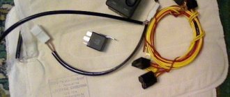
To connect the radio we need:
- The car radio itself, the speakers and their wires
- Stationery knife or special knife. tool for removing insulation from wires.
- Insulating tape.
- Fuse (10a-15a) and its connector.
- Multimeter or test light.
- Crown battery
The simplest option is that the car has audio preparation.
Audio preparation – i.e. Special connectors, an antenna are installed in the car's wiring, and speakers are fixed in standard places. For many models, audio preparation is an option, and many owners refuse it in order to reduce the cost of the car when purchasing, but this should not be done, since radio installers will ask for much more money for it.
With factory audio preparation, installing a radio comes down to purchasing an adapter between the wiring connectors and your radio.
Adapters are freely sold in most stores that sell radio tape recorders, but if you want to save money, you can order them on AliExpress.
The adapters look like this:
The second most difficult option is that the car does not have audio preparation, but a radio tape recorder was previously installed (for example, a cassette).
In this case, you need to replace the radio connector with a new connector (or maybe you’ll be lucky and they will match).
The diagram for connecting a car radio looks like this:
Most likely after you cut off the old radio connector (it’s better to do this with the battery terminal removed). You will have several wires and you need to determine where they are coming from, usually you need to find the permanent positive, positive from the ignition, ground and speakers.
How it's done?
Note (sometimes this wire is connected to a permanent positive, but in this case the radio will drain the battery, since it will not have a standby mode)
All of you can connect the radio. If everything is done correctly, it will light up.... But you also need to connect speakers and an antenna to the radio.
Connecting speakers.
You have 10 wires left. One of them is an antenna cable, one plus antenna power and 8 wires from the speakers.
Wires from speakers usually come in pairs, but their markings are not always correct. Therefore, we need a crown battery.
We attach it to a pair of wires for 1-2 seconds and listen to which speaker clicks. Next, we look at the speaker itself and connect the battery again. If the speaker goes forward, then the polarity is correct, and we screw it + to + and – to -, in accordance with the diagram. If the speaker goes inside, it means the polarity is wrong and we connect it the other way around.
Here's a video on how to determine speaker polarity:
It is very important to monitor the polarity, otherwise the sound in the car will be of very poor quality!
We consistently check and connect all the speakers, front left. Rear left, rear right, front right.
Connecting an antenna usually does not cause any difficulties.
Here is a short video about connecting a car radio, but the red and yellow colors are mixed up (as written correctly in the article):
The third most difficult option is to install a car radio in a car without audio preparation for the first time.
Don't be alarmed, there is a lot less text here since there is no need to determine the purpose of the wires. The labor intensity is higher since we will be laying these wires!
The connection diagram does not change:
- We draw a constant positive from the battery, always through a 10-15 ampere fuse, with a wire of 2.5-4 squares!
There is an option to take a permanent plus from the cigarette lighter, but as practice has shown, usually the cigarette lighter is powered by a 1.5 square meter wire and has a 10 ampere fuse. In my car, when the tire inflation pump was connected and the radio was running, this fuse burned out!
- We look under the panel (for example, on the fuse block or on the ignition switch) for the wire where the plus appears when the ignition is turned on, and accordingly, from there we pull the wire to the plus of the radio, which is responsible for turning it on. You can hook this wire to a permanent plus, but the radio will drain the battery!
- We lay the ground wire and securely fasten it to the body (for example, to fasten a panel to the body)
- We install the speakers in their regular places and lay their wires, be sure to observe the polarity!
- We connect the antenna and its control wire.
The installation of the radio is complete, you have just saved 1.5-3 tr.
The most complex option is that the car radio is installed in a car with non-standard wiring (trucks and vintage cars).
Therefore, they connect the car radio to one battery (the one with the minus side attached to the car body), and from its plus they pull the wire into the cab to the radio. This solution does exist, but it has a significant drawback - after 1-2 weeks of inactivity, the battery will be severely discharged and it will be impossible to start the engine without charging it!
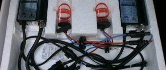
To prevent this from happening, it is necessary to use a special voltage converter. It looks like this:
Usually they refuse the memory of the radio and connect the device according to this scheme:
As a result, the memory function of the radio will not be used, but it will not drain the battery and, most importantly, there is no need to run a non-standard wire from the battery into the cabin.
The converters themselves are sold in online stores; as an option, consider purchasing on aliexpress.
In the case of vintage cars, non-standard supply voltages (6 volts) or + on the car body are possible. Connecting a car radio in such cars is decided individually each time and has no general recommendations.
ISO pinout or pinout is the identification of each electrical connection pin in a connector or diagram according to its corresponding numbering and functionality. The speaker system of any manufacturer is connected to the standard ISO connectors of the car. Proper pinout will help you get a good sound at the output and not burn out the connectors with voltage. You can understand the wires using standard diagrams. You can install any brand of car radio without having specialized knowledge in electrical engineering. When working with non-standard connectors, do not forget about safety. “Ring” the wires using a multimeter.
How to properly connect a car radio
Connecting the car radio is done in several ways:
- Using an ISO connector.
- Without using chips by splicing wires.
- By directly connecting the power wires to the battery terminals.
- Via the ignition switch or a separate switch.
- Through a security alarm.
Car radio diagrams, which help with the correct connection, are printed on a label on the top cover of the device. They indicate the color marking of the wires established by the generally accepted standard:
- red - power management;
- yellow - power supply to memory and amplifier;
- black - mass;
- blue with a white stripe - power supply to the antenna with amplifier.
For reliable fixation, the wiring can be secured using cable ties.
Connection with and without chip
The first option for connecting the radio to the car is suitable if you have an ISO connector, which is built into recently released devices. If the tape recorder is equipped with a proprietary connector, then you need to purchase an adapter suitable for it, which may or may not be equipped with an additional feature. In the first case, if there is a mating part in the car wiring, the connectors are inserted into each other.
In the event that the proprietary adapter or the radio itself does not have a chip, the cable is connected by twisting or soldering the wires. The last connection option without a chip guarantees a more reliable connection. The car radio circuit determines the purpose of the wires by color and the presence of additional contacts. Some car video players have a parking line. It connects to the parking brake button. This feature allows you to watch movies in the car while the handbrake is on.
Direct to battery
This connection method is applicable for high-output radios equipped with a subwoofer, when the capacity of the ignition switch contacts becomes insufficient for reliable operation of the device. This method is also used in the case when, when passing through the “Off” position. The ignition switch de-energizes all consumers connected to it, as on domestic cars. The cable connected to the battery must have a thickness of at least 3 square meters. mm.
First, the cables are laid in the engine compartment away from hot and rotating parts. To install the wires under the dashboard of the car, use the existing hole, which, after installing the radio, is sealed to protect it from precipitation.
To connect to the battery terminals, a nut is unscrewed on each of them, after which the stripped end of the wire from the radio is inserted under the bolt, put in place and screwed.
The attachment point is treated with WD-40 to protect against corrosion.
In accordance with the connection diagram of the radio, the plus from the battery is connected to the red and yellow wires, the minus to the black. A fuse with a rating of at least 10 A is inserted into the positive wire. It provides additional protection against short circuits and overloads.
Through the ignition switch
Connecting the radio in the car through the ignition switch allows you to avoid premature battery discharge during long-term parking by disconnecting the yellow wire of the radio, which is responsible for power supply during operation of the device. The red wire of the radio is connected to a DC power source.
The yellow wire, according to the car radio connection diagram, is screwed to the ignition switch terminal, which is energized in the “Ignition on” key position. This can be determined by a control lamp. With this method, you can use the radio only when the ignition is on. Otherwise, the functionality of the device is limited to clock operation, CD ejection, etc.
Through a button instead of the ignition switch
You can also connect the radio in your car via a button. It can be used to turn off the power supply to the red wire if the audio device is not used for a long time to avoid quickly draining the battery - just like through the ignition switch. The button, which must be locked in the on position, is installed in the free space on the dashboard provided by the car manufacturer.
To connect the radio via a button, one of its terminals is connected to any wire in the on-board network that carries the “plus”, the other to the red wire of the device. For it to work, you need to press the button. When leaving the car for a long time, you should turn off the power using the toggle switch.
What is iso
ISO is an international organization that develops standards and regulations for various industries. The abbreviation sounds the same in all languages. A Russian manufacturer working in accordance with standards labels its products with the abbreviation “ISO” or “ISO”. All well-known developers of car radios equip their products with two types of standard plugs. Each looks like an eight-pin rectangular connector.
Pinout of a standard Euro connector
A Euro connector is a standard plug used in most countries around the world. When connecting equipment, you may encounter non-standard wires tangled in a bundle. This problem is solved by purchasing adapters and pinouting the radio chips.
Standards 1din and 2din
Speaker system connectors come in two types: non-standard ones from the manufacturer, mostly pin-type, and standardized European ones, which are located at the back. Installation of equipment with a special audio connector from the manufacturer will require the use of a special proprietary connector. If the plug is ISO, then you can connect to it directly. There are two types of Euro connectors: 1din and 2din, the difference is in the height of the car radios. The two-block one is twice as tall; it is not connected to all cars, because there is no space on the panel for the required dimensions.
Radios with European 1din are the most common.
When installing car radios, wires with a small diameter of 1.5-2 mm are used, for power lines - with a large cross-section. Failure to follow these simple rules will distort the sound and damage the equipment.
Manufacturers in Japan, the USA and some Chinese use the 2din standard.
Upper power connector A
The plug is used to supply electricity to the receiver, antenna and amplifier, as well as when it is necessary to control the backlight or turn off the sound signal. Standard color markings are used. Outputs 1-3 and 6 are not used in low- and mid-price segment speakers; they are intended for additional options for high-end products.
Connection types
- The first is the connection in the socket of wires of two colors, yellow and red, turning the receiver on/off does not depend on the ignition. The method is inconvenient because it predisposes the battery to discharge if the acoustics are not turned off;
- The second wire is connected through the ignition switch, the yellow wire is connected to the on-board computer.
Functional purpose of the receiver outputs
| ANT | The connector is used if the car has a retractable antenna |
| Remote | Multiple speakers can be connected |
| Illumination | Allows you to change the intensity of the device's glow |
| Mute | Adjusting the sound |
| A4 | Turn on/off |
Pinout of radio ISO connector
| A 4 | Color yellow | Battery + Power |
| A 5 | Color blue | Antenna. |
| A 6 | Color orange | Backlight |
| A 7 | Color red | Ignition, 12V. When disconnected, reset settings to factory settings. |
| A 8 | Color black | Acoustics |
Bottom speaker connector B
Used to connect amplifiers (2 cables each). The sound of the equipment depends on whether all connectors are connected correctly. The main thing is not to confuse them, otherwise the acoustics will be of poor quality.
Rules for connecting speakers by color marking of wires
| Color white | Left front |
| Color grey | Right front |
| Color green | Left rear |
| Color violet | Right rear |
LADA Granta with EnjoY Pro
Connector “X1” (20 pins)
- A2 Front left loudspeaker (“+”)
- A3 Loudspeaker front left (“-“)
- A4 Rear left loudspeaker (“+”)
- A5 Rear left loudspeaker (“-“)
- A7 “ACC” position of the ignition switch
- A8 Reverse signal
- A11 Front right loudspeaker (“+”)
- A12 Front right loudspeaker (“-“)
- A13 Rear right loudspeaker (“+”)
- A14 Rear right loudspeaker (“-“)
- A17 Terminal “15” of the ignition switch
- A19 Terminal “30” battery
- A20 “Mass” (“-“)
Connector “X2” (40 pins)
Connector “X3” (5 pins)
- D1 VBUS
- D2 DD3 D+
- D5 GND
Connector “X8” (2 pins)
- M1 AM/FM signal
- M2 AM/FM GND
Connector “X9” (2 pins)
- O1 GNSS signal
- O2 GNSS GND
Connector “X10” (2 pins)
- P1 GNSS signal
- P2 GNSS GND
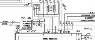
Schematic diagram for connecting the MMC of GRANTA vehicles
: 220A – multimedia navigation equipment (IVI); 312A – rear view camera; 313A – audio system microphone; 408A – reverse light switch; 569A – FM antenna; 748 – front right loudspeaker; 749 – front left loudspeaker 750 – rear right loudspeaker; 751 – rear left loudspeaker; 817A – USB connector; 903 – automobile terminal of the “ERA-GLONASS” system; 911-ERA-GLONASS antenna.
Dual ISO connector
The standard audio systems of some cars are connected with a double plug. The pinout of connectors for them is standard. The contact halves are connected to each other by a durable plastic jumper and secured with a special clamp. For correct installation, a guide groove is used, which prevents the plug from being installed in the wrong position.
The black one connects a current source to the radio, the brown one for acoustics.
Adapters for ISO connectors
Cutting off a non-standard standard plug and connecting the wires directly is not recommended, because over time the connection will become loose, may oxidize, you will have to solder not only the wiring, additional repairs will be required, replacing blown fuses. Sometimes there are acoustics with three outputs, but they have standardized markings and electrical circuits that allow you to connect standard cables to the device using pinouts. You can buy any type of adapter for ISO connectors from one model to another.
The car may not be equipped with connectors, then you need to connect the radio connector to the cable directly. This is done by twisting, soldering, or using a terminal block that does not require subsequent insulation. When twisting and soldering, heat shrink tubing is used for safe use of the equipment.
Pinouts for various brands of cars and radios
Before getting started, read the instructions for the receiver, and also pay attention to the markings and features of the product itself. The pinout of radios is influenced by standard connectors in different cars.
Pinout diagram for ISO connectors for pioneer radios
Connecting the acoustics of this well-known brand, which is popular among motorists, has some features. Be sure to read the installation manual before starting work. Installation is simple, the main thing is to understand the purpose of each color. In addition to the instructions, the kit includes two “chips” with 4 pairs of contacts: for power and acoustics.
In order not to burn out the acoustics, before connecting the speakers you need to connect the radio, check that it lights up and switches.
toyota
The pinout of acoustics of this brand is carried out according to standard diagrams. It is optimal to choose a power supply system from a battery, in this case there is no risk of its discharge.
| № 1 | A+ |
| № 2 | GND |
| № 3 | BAT+ |
| № 4 | Backlight |
| № 5 | Antenna |
| № 6 | Speakers (RR+, RR-, RF+, RF-, LF+, LF-, LR+, LR-) |
When connecting the radio, standard circuits are used.
| № 1 | ANT |
| № 3 | L.R. Line output |
| № 4 | GND. Line output |
| № 5 | R.R. Line output |
| № 6 | CD–LCH |
| № 7 | CD - GND |
| № 8 | CD–RCH |
| № 9 | CD - Reset |
| № 10 | CD – CD clock out |
| № 11 | CD – DSPL select |
| № 12 | CD – data out |
| № 13 | CD – clock in |
| № 14 | CD – data in |
| № 16 | A+ |
| № 17 | GND |
| № 18 | ANT GND |
| № 22-27 | Speakers (LF-, LR+, RF-, RR+, LF+, LR-, RF+, RR-) |
| № 28 | Mute |
| № 29-30 | Speakers (LF-, LR+, RF-, RR+, LF+, LR-, RF+, RR-) |
| № 31 | ANT CONT |
| № 32 | CD ACC Constant |
| № 33 | AMP Constant |
| № 34 | BUP |
nissan
| № 1-6 | Speakers (LR+, RR+, LR-, RR-, LF+, RF+) |
| № 7 | A+ |
| № 8 | Backlight |
| № 9 | BAT+ |
| № 10 | Speakers LF- |
| № 11 | RF speaker |
| № 12 | Antenna |
| № 13 | GND |
honda
All models of car radios are equipped with a universal European plug for connection to the socket.
| № 1 | Speaker RR+ |
| № 2 | Speaker LR+ |
| № 3 | Backlight |
| № 4 | BAT+ |
| № 5 | A+ |
| № 6 | Antenna |
| № 7-10 | Speakers LF+, RF+, RR-, LR- |
| № 13 | GND |
| № 14-15 | Speakers LF-, RF- |
Standard European pinout.
alpine
Alpine TDE-7823W: 1 – BAT+,
| № 2-5 | Speakers LR-, LR+, RR-, RR+ |
| № 7 | Amplifier |
| № 8 | Antenna |
| № 9 | GND |
| № 10-13 | Speakers LF-, LF+, RF-, RF+ |
| № 5-12 | A+ |
mitsubishi
All models use standard European speaker pinout.
| № 1-2 | Speakers RR+, LR+ |
| № 3 | Antenna control |
| № 4 | Backlight control |
| № 5-8 | Speakers LF+, RF+, RR-, LR- |
| № 10 | A+ |
| № 11 | BAT+ |
| № 12 | Backlight control |
| № 13-14 | Speakers LF-, RF- |
| GND |
Lada Kalina Hatchback 103 kW / MT › Logbook › Restoring the CAN bus MMC Kalina 2
Hurray restored! detailed instructions FOR MMC KALINA 2/PRIORA! ARCHIVE WITH FIREWOOD AND FILES A method for restoring the CAN firmware of the MMC controller.
To restore the firmware we need:
1.
USBDM programmer/debugger/emulator, then programmer. Can be purchased on aliexpress 2.
From the
Drivers , install the driver corresponding to your system.
We connect USBDM to the computer. The system must recognize the device and install drivers. 3 3.
From the USBDM 4.10.6.250 folder , run the file HCS12_FlashProgrammer.exe If the programmer is working properly and the drivers are installed, we will see this picture
4. Solder the pins to connect the programmer to the MMC
(THIS IS FOR GRANTS!) Connection points on the Grants board We make jumpers and connect to the diagnostic connector this is for KALIN AND PRIOR!
Pinout of the tail of the programmer!
5. Connect the programmer to the MMS
>>>>>>>>>FOR GRANT!
There is no need to supply power to the MMS! >>>>>>>>>FOR KALIN AND PRIOR CONNECTED TO THE CONNECTOR, MMS IS MANDATORY TO TURN ON AND GO TO THE WORK DESK! On the Target tab, click Detect Chip.
If everything is in order, our chip will determine ID F180. Select G-MC9S12G96 from the list. If ID
is not detected, see if the connection to the MMC is correct, and the position
of the power selection jumper inside the programmer should be 3.3V or 5V .
I personally changed the jumper
6. Click Load Hex Files
, select the firmware we need: MMS_CAN_bootloader_1_13.s19 MMS_CAN_bootloader_1_7.s19 MMS_CAN_bootloader_1_7_07E8.s19 – CAN firmware with diagnostics. Click Program Flash If the chip was registered successfully, we will see a window asking you to flash another chip, answer NO.
Disconnect the programmer from the MMC and check the CAN version. Turn off the power from the MMC, turn it on and check the CAN version. (this step is for KALIN and PRIOR)