Car players that exist today have a huge selection in their functional qualities, appearance, cost and other technical, quality and social parameters. But no matter how much this device costs, what functions and options it has, how well the radio will perform its direct duties. Namely, the playback of sound and video recordings from various media of such information largely depends on how the said head unit is correctly connected to the power supply system of your car - the battery.
Scheme
Pinout of a standard Euro connector
A Euro connector is a standard plug used in most countries around the world. When connecting equipment, you may encounter non-standard wires tangled in a bundle. This problem is solved by purchasing adapters and pinouting the radio chips.
Standards 1din and 2din
Speaker system connectors come in two types: non-standard ones from the manufacturer, mostly pin-type, and standardized European ones, which are located at the back. Installation of equipment with a special audio connector from the manufacturer will require the use of a special proprietary connector. If the plug is ISO, then you can connect to it directly. There are two types of Euro connectors: 1din and 2din, the difference is in the height of the car radios. The two-block one is twice as tall; it is not connected to all cars, because there is no space on the panel for the required dimensions.
Radios with European 1din are the most common.
When installing car radios, wires with a small diameter of 1.5-2 mm are used, for power lines - with a large cross-section. Failure to follow these simple rules will distort the sound and damage the equipment.
| № 1 | — |
| № 2 | — |
| № 3 | — |
| № 4 | Constant power |
| № 5 | Antenna power |
| № 6 | Backlight |
| № 7 | Ignition |
| № 8 | Weight |
Manufacturers in Japan, the USA and some Chinese use the 2din standard.
Upper power connector A
The plug is used to supply electricity to the receiver, antenna and amplifier, as well as when it is necessary to control the backlight or turn off the sound signal. Standard color markings are used. Outputs 1-3 and 6 are not used in low- and mid-price segment speakers; they are intended for additional options for high-end products.
Connection types
- The first is the connection in the socket of wires of two colors, yellow and red, turning the receiver on/off does not depend on the ignition. The method is inconvenient because it predisposes the battery to discharge if the acoustics are not turned off;
- The second wire is connected through the ignition switch, the yellow wire is connected to the on-board computer.
Functional purpose of the receiver outputs
| ANT | The connector is used if the car has a retractable antenna |
| Remote | Multiple speakers can be connected |
| Illumination | Allows you to change the intensity of the device's glow |
| Mute | Adjusting the sound |
| A4 | Turn on/off |
Pinout of radio ISO connector
| A 4 | Color yellow | Battery + Power |
| A 5 | Color blue | Antenna. |
| A 6 | Color orange | Backlight |
| A 7 | Color red | Ignition, 12V. When disconnected, reset settings to factory settings. |
| A 8 | Color black | Acoustics |
Bottom speaker connector B
Used to connect amplifiers (2 cables each). The sound of the equipment depends on whether all connectors are connected correctly. The main thing is not to confuse them, otherwise the acoustics will be of poor quality.
Rules for connecting speakers by color marking of wires
| Color white | Left front |
| Color grey | Right front |
| Color green | Left rear |
| Color violet | Right rear |
Connecting a car player via the ignition switch or button
These connections are recommended as an answer to the question of how to connect the radio so as not to drain the battery.
This is done through the ignition switch as follows:
- The yellow cable (plus) is fixed to the positive terminal of the 12V car battery.
- The red power wire is connected to the ignition (lock).
- Black (ground), goes to a car body part.
This connection is considered the most common and is recommended by experts. The positive and negative sides of this connection method are mutual. That is, the battery does not discharge while in a standby state when the car is parked. But you can listen to music only when the ignition is on.
Connection via a special button.
The wires are connected according to the diagram described above (ignition), with one exception. The red power wire is not connected to the ignition switch, but to the intermediate button. With a cable leading from it to the positive terminal of the battery. Thus, the player can be used without turning on the ignition, and also completely disconnected from the energy carrier (battery).
Connecting an ISO type car radio
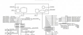
When all the necessary tools are ready for work, you can start connecting. Next, we will look at how to properly connect a car radio with an ISO connector. A special diagram will help us with this, on which you can see which wires are responsible for what and where they go. So, for example, on the left side of the diagram the power connection for the car radio is shown, and on the right is the output to the speakers.
Let's start with connecting the power, since it is at this stage that most mistakes are made. Three wires are responsible for powering the car radio, each of which performs a specific function.
Yellow wire for 12V
This wire is the main one, since it is responsible not only for powering the built-in amplifier, but also for saving the car radio settings. When connecting it, you must use a 10 amp fuse, and the approximate length of the wire should be 30 cm. In addition, yellow wires marked B+, BU or BATT are very common. They can also be used.
Red ACC wire
This wire is responsible for controlling the power of the car radio. Simply put, power will be supplied to the radio only when the ignition key is in the desired position. Surely you have noticed more than once that when you turn the key to the ACC position in the car, the stove, cigarette lighter, radio and other devices start up.
Black wire GND
The wire marked GND is connected to the negative terminal of the car battery. Some car enthusiasts prefer to connect it to the car body, but this is only relevant in cases where the car radio has low power
It is also very important when connecting the GND wire to the car body, thoroughly clean the connection point, thus ensuring good contact
When the car radio is provided with power, you can proceed to the output to the speakers. For this purpose, there are also special wires that are laid to one or another column:
- Front Left (FL) – front left speaker
- Front Right (FR) – front right speaker
- Rear Left (RL) – rear left
- Rear Right (RR) – rear right
It is worth noting that some car radios have not only wires like FL, FR, and so on, but also so-called tulip connectors. If your speakers are equipped with these types of connectors, you can use them for connection. Otherwise, you need to know which other wires are responsible for what.
White ANT wire
The wire with this marking is responsible for controlling the car radio's antenna. Depending on the signal quality, it supplies power to the internal active antenna or to power the external antenna.
Wire marked ILL (Illumination)
The color of this wire may vary depending on the manufacturer. Most often this is a light pink or yellow version of it. The wire marked ILL is connected to the side lights, to positive. It’s easy to guess that it is responsible for the car radio’s backlight.
MUTE
Responsible for muting the sound when a button is pressed.
How to turn on via a step-down transformer
A simple rectifier on a step-down transformer from a 220 V network
The implementation of this option is more difficult, but for those who love to tinker, it will not be difficult. We won’t tell you how to wind a transformer. We assume that you already have it and with the necessary parameters. Namely:
- input voltage 220–230 V, output - 12 V;
- power - from 120 watts depending on the audio system;
- current up to 10 A.
At its output we will have 12 V AC, and the car radio is powered by DC. Therefore, this tension must be straightened. You can assemble an elementary circuit using a diode bridge and a capacitor.
Diodes, for example, KD226, it is better to set the capacitor at 4700 μF to reduce ripple. Before connecting, check the output voltage parameters. Without load it can be slightly higher and amount to 14 - 15 volts.
Useful tips
To ensure reliable contact in the connections of power points, it is recommended to twist the copper wires and then reinforce the joint with solder or a metal tube and crimp with a special tool. In the radio section, a separate cable is used, which is responsible for illuminating the buttons and display, which is led to the lamp brightness control on the instrument panel. When the ignition is turned off, the backlight turns off automatically or by a signal from the delay timer, without affecting the saving of settings.
If the car owner wants to maintain the functionality of the head equipment, regardless of the position of the key in the ignition switch, then the red wire is routed past the starter control contact group. A push-button switch is installed on the instrument panel, allowing you to manually turn the power on and off. It is not recommended to leave the power active even when turning off the car radio using the button on the front panel. The amplifier and electronic components consume a current of 0.5-1.0 A, which drains the battery.
Source
Connection via ignition
In order to avoid a situation with the battery discharging during long-term parking, many drivers connect the radio through the ignition switch. To do this, there is a wire responsible for powering the contact group of the lock; the positive wires from the radio are connected to it. In this case, when the ignition is turned off, the playback device is disconnected from the power supply.
The disadvantage of this method is the need to turn on the ignition if you want to listen to music. This may lead to increased battery drain.
Do-it-yourself car radio installation and connection
Installing a car radio is a creative process, but not very complicated. An experienced car enthusiast, at least a little familiar with the basics of electrical engineering, will be able to connect the car radio with his own hands without any problems. We will tell you in this article how to properly connect a radio in a car, and in what order this should be done.
It should be remembered that an incorrectly installed and connected radio will not only sound bad, but may even lead to a short circuit or even a fire in the car.
A good video instruction for installing and connecting a car radio in a car can be seen in the video at the bottom of this page.
Incorrect connection of the car radio causes the following problems:
- When parked, the radio consumes too much electricity, as a result of which the battery is constantly discharged and if parked for a long time, there is a chance that the engine will not start.
- When listening to music at high volumes, the radio starts to “stutter” and significant distortion of the sound signal appears. Also, at high volumes, the car radio may simply turn off.
- When you turn off the power, the radio settings are lost.
All of these problems in 90% of cases arise due to incorrect connection.
How to connect a car radio in a car with your own hands? (photo - video instructions)
Good afternoon. In today's article I will tell you how to connect a car radio in a car and analyze typical errors in connecting radios. Traditionally for our site, the article is equipped with detailed photos and video instructions.
If, when connecting, you arrange the so-called. A short circuit can lead to melted wires, burns and, in extreme cases, a fire. Please, when connecting the car radio, be careful, carefully insulate all wire connections and do not forget about the fuse...
To connect the radio we need:
- The car radio itself, the speakers and their wires
- Stationery knife or special knife. tool for removing insulation from wires.
- Insulating tape.
- Fuse (10a-15a) and its connector.
- Multimeter or test light.
- Crown battery
The simplest option is that the car has audio preparation.
Audio preparation – i.e. Special connectors, an antenna are installed in the car's wiring, and speakers are fixed in standard places. For many models, audio preparation is an option, and many owners refuse it in order to reduce the cost of the car when purchasing, but this should not be done, since radio installers will ask for much more money for it.
With factory audio preparation, installing a radio comes down to purchasing an adapter between the wiring connectors and your radio.
Adapters are freely sold in most stores that sell radio tape recorders, but if you want to save money, you can order them on AliExpress.
The adapters look like this:
The second most difficult option is that the car does not have audio preparation, but a radio tape recorder was previously installed (for example, a cassette).
In this case, you need to replace the radio connector with a new connector (or maybe you’ll be lucky and they will match).
The diagram for connecting a car radio looks like this:
Most likely after you cut off the old radio connector (it’s better to do this with the battery terminal removed). You will have several wires and you need to determine where they are coming from, usually you need to find the permanent positive, positive from the ignition, ground and speakers.
How it's done?
— We expose the wires using a utility knife and arrange them so that they do not short-circuit.
— We put the terminal on the battery.
— We connect one terminal of the test lamp (or multimeter) to the car body (ground) and with the second terminal, sequentially, we touch each of the exposed wires. When the light comes on or the multimeter shows voltage, congratulations, you have found a permanent positive.
— It’s better to immediately twist it with the radio connector (usually the wire is yellow and BAT +12v is written on it) and insulate it with heat shrink or electrical tape. A fuse with a rating of 10-15 amperes must be installed on this wire.
— We are looking for the plus from the ignition switch, to do this we open the lock to the “ignition on” position and similarly, using a multimeter or a light bulb, we look for the required wire. The found wire must be connected to the red wire of the radio connector (usually ACC+ is written on the wire); we do not isolate it yet!
Note (sometimes this wire is connected to a permanent positive, but in this case the radio will drain the battery, since it will not have a standby mode)
— We are looking for ground, to do this we disconnect the control lamp from the body and connect it to the last twist we just made and connect the second terminal of the control (multimeter) in series with the remaining wires. Once the light comes on (or the multimeter shows voltage), you have found ground. We connect it with a twist to the black wire of the radio connector (usually it is labeled gnd, ground)
Do-it-yourself power supply
What kind of homemade power supply is needed?
The power supply can be assembled completely independently. It will operate from a 220 volt network. Thus, through it you can connect a car radio and listen to music in your own garage without disturbing your neighbors. The primary task will be to obtain a constant voltage of 14 V from a 220 V outlet. Everything seems clear, but on the other hand, a car radio with speakers and full volume is a very power-consuming device. Here you need as many amps as possible.
Simple 220 V mains power supply
So let's get started:
- We find a future blank for payment;
- We remove everything unnecessary from there: microcircuits, capacitors, etc.
- The diodes should be KD203A, although others are possible, as long as they can withstand the current passing through them;
- As for capacitors, one of them should be 2000 µF, and the other should be 100 µF.
- After that, all that remains is to select the microcircuit. We take into account what speakers the homemade power supply will work with. If the speakers are small, then the microcircuit can be taken at 3 Amperes;
- We install a stabilizer, for which you need to prepare a seat on the board with fine-grained sandpaper. We just take the skin and clean it;
- The stabilizer is treated with heat-conducting paste KPT-8;
- We place it on the radiator using a clamp;
- We take a soldering iron and solder the entire circuit using the surface-mounting method.
Checking the assembled power supply is the most important and responsible part of the work. If the output is 13.7 Volts, then this is quite enough to drive a couple of small speakers.
We connect the radio with a homemade power supply. The yellow and red wires go to the positive, the black to the body.
The above instructions will allow you to select or make a power supply for your car radio with your own hands. It will be useful to watch a thematic video review or photo materials. The price of a computer power supply, as mentioned above, is low and you can even find it at home, in a pile of unnecessary hardware.
Connect via computer power supply
Any computer power supply produces +12 V and at least 10 amperes in this circuit. This is the voltage that needs to be supplied for the car radio. The first thing to do is start the power supply. In order for it to work when plugged into the network, you need to short-circuit the black and green leads. They are output to the power supply connector for 4 or 24 outputs. They must be connected with a jumper. Or cut off the necessary wires, strip the insulation, twist them together and insulate them.
Stages of work, wires and pads
When the power supply is turned on, the fan should start working.
Where to get 12 V on the computer power supply
We take the power supply connectors and look for the yellow wire. Usually there is a large connector and several small ones. The “large connector” can have 12 or 24 outputs. Depends on the block model. But the yellow wire is still there.
Where to look for 12 V on a computer power supply
The small connectors that go to peripheral devices also have a yellow wire and 12 V. You can take the power from there.
This is what a computer power supply looks like
You can make sure that it is working correctly by taking a multimeter and measuring the voltage on the yellow wire. On the multimeter we set the DC voltage measurement to 20 volts.
The stripped wire can be inserted into the block. But it’s better to cut off the wire, strip it and connect it to the desired conductor from the radio.
The second black wire we need is negative.
All this work - removing, cleaning, connecting - is carried out with the power supply unplugged.
How to connect wires
On the radio, power is supplied to the red and yellow wires. If you have a connector, you must either insert the wires into the appropriate sockets, or cut off the block and strip the necessary wires. If you decide to cut off the block, twist the wires that supply power to the car radio together. And we connect them to the yellow wire from the computer power supply.
We connect the black wire of the radio to the black wire from the power supply.
After turning on the power and connecting the speakers, you can enjoy music at home, in the garage or in the country house
If the block has not been cut off, you need to install a jumper between the red and yellow wires (you can use a piece of wire with stripped ends). Plug the yellow wire from the power supply into one of the connectors with a jumper. So it turns out that power is supplied to both inputs at once.
How to connect a radio if there is no ACC wire?
If there is no ACC wire, but you need to connect the radio, you can take one step: connect the power wire to the ACC, which will allow you to use the radio without an ACC wire, but at the same time, the GU will drain the battery much faster. Even a non-working radio will consume many times more energy than when connected to an ACC cable.
Attention. When connecting the GU for the first time, be extremely careful when connecting the wires and special attention should be paid to the correct connection of the contacts
Any mistake, be it a bad twist, a short circuit or incorrectly connected contacts, can damage your device.
Connection features
How to connect the radio directly to the battery? This depends on some features of the radio you purchased. Particular attention should be paid to the connector through which power is connected to this media device. The most convenient to use are universal connectors (ISO), connecting a new radio will be as easy as shelling pears, just rearrange the chip with wires to the new equipment. If you have a custom connector, you will have to buy an adapter. Also, some car enthusiasts simply connect the wires to the radio in accordance with the diagram.
Connection options
Power is supplied to the player using 3 wires: 2 power 12V wires with different polarities (yellow and black) and ACC. The +B contact continuously supplies voltage to the connected equipment, which allows you to save settings even after it is turned off.
Incorrect installation via the cigarette lighter or ignition switch (connection entirely to this element) is indicated by the following:
- a car battery is completely discharged in 2 days;
- the backlight on the radio display flashes involuntarily;
- The player turns off completely when the power is increased.
In case of problems, the ACC contact on the radio should be left on the ignition switch, and the remaining wires should be connected to other elements.
Option #1
In this case, the yellow +B wire is connected through a new 10 A fuse to the contact running from the battery to the fuse block and placed in a random location. The red ACC wire from the radio is connected to the ignition switch to provoke the flow of current to the player by turning the key, and the remaining wire with negative polarity (GND) is connected to the negative terminal of the battery.
This installation option eliminates the possibility of manually turning on the radio, so you cannot listen to music when the engine is turned off.
Option No. 2
In order to use the player regardless of engine operation, the previous circuit is improved with diodes that can withstand a voltage of 15 V (no more than 0.1 A) and the use of a blue REM wire, which is connected to the ACC contact. Diodes are inserted into ACC and REM in such a way as to create a circular power supply circuit for the device. When voltage is applied to the blue wire, the limiting element should return it back to the ACC terminal, breaking the circuit between the ignition switch and REM.
If the connection is correct, the radio can be started manually after turning the key. To save battery life, it is recommended to remove the key from the ignition switch after turning off the player.
Option #3
This circuit does not imply the use of a REM contact, but you will need a five-pin relay to which all existing wires are connected, except for the power GND - it is still attached to the negative contact of the battery or to the body. The option works as follows: turning the key provokes the supply of current from the ACC ignition switch to the contact of the relay winding connected to the positive contact (yellow wire), for autonomous operation and replenishment of the ACC.
The diodes will limit the flow of current, preventing it from returning to the ignition switch, so the equipment can operate regardless of the position of the key.
The second contact of the winding is connected to the negative connector for blocking the engine in the alarm unit.
This will allow you to break the power circuit when you turn on the security system and activate the voltage supply to the radio by turning the key. This option eliminates the possibility of accidentally leaving the player on and saves battery life.
. Correct power connection
To supply power from the battery to the car receiver, three main wires are used: red, black and yellow. Where:
- The black wire corresponds to the negative charge (minus) of the battery.
- Wire in yellow braid, positive value (plus) of the battery.
- Red - positive wire from the ignition switch of a passenger car.
- The main way to fully answer the question of how to connect a radio via a battery correctly is the following diagram:
- The black cable is connected to any element of the car body convenient for these purposes, that is, to ground.
- Yellow - directly to the positive output of the battery. With intermediate installation of a 10 - 20 Ampere safety device.
- The red wire also goes to the positive, but this time to the ignition switch.
For such connections, you should select a copper, multi-core cable with a cross-section of at least 4 millimeters in a reliable insulating braid.
Let's save the radio's memory when the power is turned off.
Currently, any car radio (read all about radios here), even a fairly cheap one, has a wide range of service functions, for example: channel balance, tone controls, about 20 - 30 fixed tuner settings, clock, etc. And these configured parameters are required enter into memory. But to save the memory, there is no built-in power source in the radios, and any disconnection of the battery (for example, during welding work on the body, or before a long stay in the garage, turning off the mass with a powerful toggle switch so that the battery does not discharge) erases the memory. And when the power is connected, all parameters have to be restored again.
To get rid of this inconvenience, I propose a simple improvement to the standard electrical circuit for connecting the radio (head unit). You will need to supplement the radio with an additional very low-power power source, for example a 12-volt battery, and if you don’t find a twelve-volt one on sale, you can use 1.5-volt AA batteries. You will need 8 pieces (1.5x8=12). But it’s better to use only three square batteries of 4.5 volts, despite the fact that the total will be 13.5 - exactly what you need, and even a little with a margin (the radio is designed for power up to 16 volts and operates at higher voltages better). Compared to AA batteries, square batteries last three times longer. We assemble the batteries into a block in series, solder them to the wiring contacts, and then put the batteries in a stack, wrap them with electrical tape and hide them in a secluded place under the dashboard, not far from the radio.
In the standby mode of maintaining (saving) memory, the current consumed by the radio is very small, and the batteries will last for a long time. And now, for example, by disconnecting the battery mass during welding work on the body and connecting it again, or returning to your garage from a business trip and connecting your main car battery, you will not need to re-configure the radio (head unit) parameters, since the memory of all settings will be saved . Good luck to everyone!
Source
Setting up the radio
The main settings of the head unit include:
- menu language selection;
- disabling the demo screensaver;
- programming radio frequencies;
- setting the operating parameters of external players switched through the AUX port;
- adjusting the balance between speakers;
- setting frequency cutoff parameters (not available for all radios).
If an additional amplifier is used in the design of the car's speaker system, then you need to disable a similar device in the radio. Such manipulation is not required for all devices. Then the parameters of the external device are separately configured (in accordance with the instructions). Do-it-yourself settings and installation do not require special knowledge, but if the user is not confident in his own abilities, then it is recommended to visit a service center that installs speaker systems in cars.
What to do
If the head equipment does not save the settings when the ignition is turned off, then it is necessary to remove the product and check the switching circuit. At the same time, the presence of voltage is checked in the circuit to which the cable with a yellow protective layer is connected. On some vehicles, an on-board electrical system control unit is mounted, which de-energizes the circuits some time after the ignition is turned off. In this case, the wire is connected to the positive terminal of the battery, which allows you to remember the settings when the ignition is turned off.
On cars manufactured by VW and GM factories, original color markings of standard wiring elements are used. The yellow cable of the head unit is connected to the red cord, and the wire with the red insulating layer is connected to the yellow wire. A similar scheme is applicable when switching devices manufactured by Alpine. After changing the circuit, it is necessary to check the functionality of the equipment; turning off the contact group in the lock should not lead to resetting the programmed parameters.
Hyundai cars use a standard harness with an ISO standard block. To switch external equipment, an adapter is used with a metal jumper installed inside, connecting the positive cables into a common circuit that goes through the lock. In this case, after turning off the ignition, the car radio will reset the settings to factory settings.
Chevrolet does not use standard electrical wiring for multimedia equipment to separate the positive circuit into two paths. When replacing the standard radio, it is necessary to use adapters that provide power to the memory unit. It is allowed to use car radios equipped with a built-in autonomous power source (for example, a lithium-ion battery). The car owner can make a power supply with his own hands, but he should remember the need to charge the batteries and periodically replace the elements.
Connection diagrams
The connection of the car radio to the vehicle's on-board network is carried out through standard wiring or connected directly to the battery. The power system must ensure uninterrupted operation of the equipment regardless of the volume level. The power supply circuit uses an additional cord to ensure that the settings are saved when the key is removed from the ignition.
The diagram attached to the factory documentation of the car radio indicates the purpose of the power cables:
- with black insulation - used to ground the radio casing to the car body;
- with a red protective layer (a yellow cord with a larger wire cross-section is used on parts of the radio) - to supply positive power to the amplifier;
- with a yellow insulator - to recharge the memory unit (a constant supply of a positive signal of 12 V is required);
- with blue protection with a white stripe - for supplying power to an external amplifier (for example, an antenna or sound).
Before connecting the car radio to the on-board network, you need to analyze the documentation and select the preferred connection scheme. To facilitate installation, the cables are color coded according to the ISO standard. An incorrect choice of switching scheme can cause equipment to turn off during operation or distortion of the broadcast sound.
Through the ignition switch
The connection diagram for the radio through the contact group of the ignition switch is possible if there is an intermediate ACC position in the device. The power wire for grounding (with a black insulator) must be hooked up to grounding elements (for example, to special bolts and nuts welded to the body). The cable is secured using contact plates, which are installed on the exposed area. The quality of the grounding determines the operation of the equipment at high volumes; if the contact is poor, the radio may turn off spontaneously.
Are you a car driver?! Then you can take this simple test and find out. Go to test »
Only a cable covered with a layer of red insulation passes through the contact group of the ignition switch. On some vehicles, it is possible to connect the cord to the cigarette lighter socket or socket for additional equipment, since power is supplied to the units only after turning the key in the ignition switch. When making such switching, the parameters of the protective fuse should be taken into account; the rating of the insert should be sufficient for the joint operation of the cigarette lighter (or additional devices) and multimedia equipment.
The yellow cable is led to contacts where positive power is constantly present.
If the wire is connected to the lock, the equipment settings will be reset to factory values each time the ignition system is turned off.
The connection point for the yellow wire depends on the car model; it is recommended to route the cord to the battery installation location.
After the ignition is turned off and the key is removed from the keyhole, the power supply to the power circuits of the multimedia device is stopped. Only the elements that ensure that radio frequencies and equipment settings are stored in memory remain energized. The switching technique ensures minimal energy consumption by the head unit when the vehicle is idle.
Installing a standard radio in a car requires switching only through the contact group of the lock. The cables used by the manufacturer are designed for the power of the built-in amplifier, which ensures reliable operation of the equipment. If the owner intends to replace the factory equipment with a device with improved characteristics, it is recommended to evaluate the compliance of the cable cross-section with the power consumption.
Direct to battery
A scheme for connecting a car radio directly to a battery installed in the engine compartment or in the luggage compartment has become widespread. The connection method is the most reliable, but the car owner must forcibly turn off the head unit when parking the car. A working amplifier can discharge the battery in 8-10 hours; it will not be possible to start the power unit with the starter in the morning.
Before connecting the radio to a DC source, you need to lay the power cables. The cords are routed from the instrument panel through the car interior and engine shield; the route is laid away from moving elements and heat sources. If there are no suitable holes in the engine shield, then it is necessary to drill the parts and install rubber seals. To ensure operation of equipment equipped with an external amplifier and subwoofer, the use of a copper multi-core cable with a cross-section of 3-5 mm² is required.
The cables are connected to the battery contact pins using special terminals, which are then coated with a protective compound. A fuse is installed in the positive line; the rating of the device depends on the power of the connected components. The fuse link is mounted at a distance of 300-400 mm from the battery contact connector. Installing a multimedia complex without a protective element is strictly prohibited.
Using a button instead of the ignition switch
Connecting the radio via a button allows you to control the power of the head unit without installing the key in the ignition. With this connection method, the red wire (positive power) is led to a switch that is mounted on the front panel or center console in the car. Installation and connection of equipment involves laying additional cables and using a button that can withstand current up to 10-15 A (depending on the power of the amplifier).
After pressing the button, the multimedia equipment is turned on; a yellow cable is used to save the settings in memory. The cord is led to the battery or attached to the positive wire of the car circuit, which constantly carries voltage. The disadvantage of the technique is the need to control the position of the switch when parking the car.
Via alarm
A security alarm can be used to connect a multimedia head unit to a car. An additional 5-pin relay is included in the equipment circuit, which breaks the power supply circuit of the radio when the security mode is activated. The switching unit is placed in the gap in the power supply wire to the amplifier; a protective fuse rated for a current of 10-15 A is installed in front of the relay. To turn off the power to the musical equipment, the external blocking control output (negative pulse) is used.
Installation of the radio and connection to the on-board network through the alarm unit is recommended to be carried out in a specialized service. If switching is incorrect, the head unit continues to consume current up to 200 mA, which leads to a decrease in battery capacity. Some security systems require the installation of an electronic unit built on low-current transistors and additional resistances. The design of the module depends on the output logic of the car alarm.
Method of connecting head equipment via a double relay and a security complex unit:
- Connect the yellow cable from the battery through pins 30 and 85 of the first relay, and then route the cable to the player.
- To contact 86, located on the first relay, lay the signal cable from the central locking control unit (negative pulse).
- Connect contact 87A of the first relay to plug 30 located on the second switching block. Contact 86 from the second relay is connected to the car body.
- From plug 85 on the secondary relay, the wire is routed to an external amplifier or antenna.
- The red wire goes through the ignition switch and the diode. Then the circuit is connected to pin 87, located on the second relay, and output to the head unit block.
Connecting a car radio
When connecting the radio, you must strictly follow the diagram. To power the car radio, you need to connect the yellow wire to the battery positive. The black wire goes to ground, this is grounding. The red wire is powered from the ignition switch. Ideally, it should be connected so that it is powered only when the key is in the ACC position.
Since installation difficulties arise precisely in the absence of an ISO adapter, all wires must be stripped and then insulated. Stranded copper wires with silicone insulation are ideal. Once the wiring is complete, they can be combined into a standard adapter, but you can also insulate them with the radio wires. The main thing is that the color of the wires of the radio and the car match each other.
It happens that the yellow and red wires are connected to the battery. The advantages of this connection are that the radio is always in standby mode and ready for use. However, this method quickly lands him. Therefore, it is worth thinking about what is more important: the operation of the radio independent of the ignition switch or the long-term operation of the battery?
Connecting speakers
The colors of the radio speaker wires have already been described above. Therefore, in accordance with them, you can safely connect any speakers.
Today, almost all car radios are oriented towards 4 speakers: two in front and two in back. It is worth noting that a powerful audio system has a plus and minus output to each speaker. A weak audio system has only a positive output. Therefore, the minus from the column is displayed on the total mass. To get better sound, it is best to observe the plus and minus contacts.
If poor sound quality occurs after installation, there is a simple and effective way to make the connection correctly. You need to transfer the sound to the front speakers, then transfer the sound to one speaker, for example, the left one. Turn on the music at full volume until wheezing or distortion appears. After that, transfer the sound to the 2 front speakers.
If the sound becomes louder and remains of high quality, then the connection is made correctly. If there is no change in volume, or distortion appears, then you need to check whether the plus and minus are connected correctly.
As you can see, connecting a car radio based on the color of the wires is not difficult and, with a careful approach, will take no more than 2-3 hours.
I mixed up the wires once when I connected the speakers. I don’t know how this happened, most likely just carelessness. As a result, the speakers worked out of phase and jammed each other, causing the sound to deteriorate greatly.
In my car, the left speaker of the radio is very wheezing. Maybe this is due to the fact that I connected the radio itself incorrectly? I'm not sure if it's connected correctly, since this was my first time doing this, and I could have messed something up.
Oh, and a puzzle - these wires. About 6 years ago I bought a Pioneer from a friend with protruding wires. He assured me that I would quickly figure it out and everything would connect fine. I struggled all day, but finally did it. I wouldn’t do such an experiment now.
Tell me, why does my car radio turn off when I turn on the headlights?
The drawdown is big. Try putting a thicker wire on the “+” or installing a more powerful capacitor (larger capacity) in the radio.
I connected the radio for the first time in a 1988 Toyota Corolla. The radio was Pioner DEH-X3500UI. The wires in the car were of the old type, you had to buy an adapter and solder the wires from the car to it, the problem with the car was that the wires were not the same color, not according to the instructions, there were pink, blue and all solid colors. I found an old manual on the Internet and found which wire was responsible for it, soldered everything, connected the radio and everything worked, I had no experience in connecting at all, since it was my first car and the first radio I bought, as they say, the eyes are afraid - the hands do!
How many amperes is the fuse in the FUSIOL radio?
Usually they cost either 10 or 15 amps
Guys, hello everyone. I recently bought an Epic 10 year old. It already had a Chinese radio on it, I want to install the original one, but the chips were cut off by some deb......m, who wouldn't mind if you could send me a diagram of how to connect it. by wire color
Well, why is there no mention in the diagrams and texts of the wire (steering wheel cont...), which is intended for connection to possible steering wheel radio control buttons.
Sony car radio connection diagram
The connection diagram for a Sony car radio implies the correctness of actions, knowledge of the purpose of the connectors and much more. This article will tell you how to install and connect car radios from this company. Sony car radios and a connector connection diagram are all that is needed to carry out the process correctly.
Checking the connection
After the installation of the car radio is completed, you need to connect the battery to the car's on-board network. Then an attempt is made to activate the multimedia head unit. If the wires are connected incorrectly, you will not be able to turn on the device; if the insulation is poor, a short circuit may occur, which will blow the fuse. To restore functionality, you will need to remove the device and replace the fuse link with a product with an identical rating.
Then it is recommended to check the correct connection of the power cords according to the colors of the radio wires. Incorrectly connected cables must be carefully disconnected and then reconnected correctly to the car radio. If the display lights up when you press the power button, then the power supply to the equipment is connected correctly. If there is no sound (regardless of the position of the control) or the amplifier periodically turns off, then you need to use a tester to check the integrity of the cables going to the speakers.
If there are no malfunctions during the operation of the equipment, then the connection of the car radio and installation of additional components are considered complete. If the owner cannot find the cause of the malfunction, it is recommended to send the car to a service center. Operating a vehicle with faulty electrical network components leads to melting of the wiring insulation and a fire.
Car players that exist today have a huge selection in their functional qualities, appearance, cost and other technical, quality and social parameters. But no matter how much this device costs, what functions and options it has, how well the radio will perform its direct duties. Namely, the playback of sound and video recordings from various media of such information largely depends on how the said head unit is correctly connected to the power supply system of your car - the battery.
Scheme
When installing a car radio, it is useful to know
During the process of installing and connecting a radio in a car, non-standard situations often arise that cannot be foreseen in any instructions.
So, if you use a standard car antenna when installing a car radio, then sometimes the length of its wire may not be enough. Many cars are still equipped with antennas designed to install old-style radios. Their antenna socket is located on a “tail” that is only about fifteen centimeters long.
In this case, you can try to connect the antenna blindly after connecting all other wires to the radio. If this fails, then, most likely, you will have to remove the console and insert the antenna plug by touch after installing the car radio in the container.
By the way, after about half an hour of this “Kama Sutra” you will probably begin to think about buying a new car radio antenna.
If it becomes necessary to remove a car radio with a removable front panel from the container, you will need to insert two flat keys included with the radio onto the sides of it until they stop. But before that, do not forget to remove the front control panel - it is usually detached with the “Release” button.
Connecting the radio to batteries via side lights
An interesting, but not very clear (at least for the author of the article) connection method. The connection is made through the red terminal of the player to the power cable for the side signals running under the front panel (torpedo). Or to a lamp illuminating the interior of the glove box (glove compartment). With this connection, the yellow cable goes through a fuse to the positive terminal of the battery. With this connection, the radio only works when the lights are on?!
How to connect a radio to a battery at home
Since a car player is a mobile device, its scope of application does not end with the car interior. And throwing away a working receiver when replacing it with a new MMC is quite a shame. In such cases, an excellent solution would be to connect the radio to a household electrical outlet or an old but working battery, at the dacha or in a garage workshop. As a connection diagram, you can select the connection option via a button (toggle switch). If a suitable battery is not available, it can be replaced with a network adapter that converts standard 220 volts into the 12V required to power the radio. Or an uninterruptible power supply with a built-in 12 V battery. With this connection, the radio is not only provided with energy, but is also reliably protected from possible power surges.
Video instructions on how to connect the radio directly to a 12V battery.
Not a bad instruction, thank you very much for it. I just want to connect through the alarm system. The method is basically clear. I think that there will be no problems with the connection, I’ll try to connect it myself.
An excellent article for those who cannot, but want to connect car radios themselves. Everything is clear, concise and clearly explained. All options for connecting a car radio and troubles with an incorrect connection are indicated. Educational article.
I recently purchased a brand new branded radio and couldn’t figure out how to connect it. It's still sitting in my trunk unused. But now I know how it’s done, so I’ll connect it tomorrow.
Where were you with this article when a year ago I connected the radio using a video from YouTube. No joke, I spent almost the whole day trying to figure out what and how. Although here the work is done with skill for half an hour maximum.
I bought a radio. I have an AUDI 80B4. Since 1996. The chips are old, that is, those that came with this car. I inserted the chips like clockwork, but in response there was silence. It didn’t even turn on. This is not the original radio. It’s just a new one. That’s not I know how to proceed. I thought I could connect anything, if only the plugs would fit. Please tell me. I’m not a big deal in this matter..
Joseph, don’t forget about the CAN bus in Audi cars; if the radio is after 2002, it may not work.
A radio is an indispensable attribute of any modern car. As a rule, more functional equipment is purchased instead of a standard device. In any case, the radio must be connected correctly. Note that there are several options for solving this problem. In this article we will list the main methods for connecting a car radio.
Almost all devices of this type today are equipped with a universal connector, thanks to which even a novice car enthusiast can handle the connection. There are also various adapters on sale that can make the task easier. Another option is to connect the wires according to a color scheme (usually it comes with the radio).
What does ACC mean on the radio?
Power to the car radio is supplied by two wires: power with a voltage of +12V yellow, black with a voltage of -12V. The ACC wire (also called signal wire) acts as a control wire and if it is not powered, the GU will not start. The ACC wire on the radio will be energized when the key is turned in the ignition switch.
The +B power wire has a constant voltage of +12V and allows you to store the necessary information in the car radio's memory (station frequencies, last played track, etc.) Unlike +V with a constant voltage, a signal is supplied to the ACC signal wire only when the head unit is running.
Connection via button
A more optimal solution is to use a button to turn the radio power on and off. Everything is quite simple here. We take the wire that goes to the plus and connect it through a regular button with two positions (on and off). This allows you to most optimally manage the power supply of the radio. When leaving the machine overnight or for a long period of time, simply turn off the power by pressing the button. Usually this button is located on the console not far from the radio itself.
Using this technique will allow you to use your musical equipment regardless of the position of the key in the ignition.
How to connect an antenna
To connect a radio receiver, you must additionally install and connect an antenna. Most often it is located on the roof or fender of the car. A stronger and more stable signal is provided by an additional amplifier, which is located in the switching circuit. Power is supplied via a separate cord. The connection diagram depends on the model of the head unit and the technical design of the amplifier itself.
In a 2 DIN radio, the round ANT connector is responsible for connecting the antenna. The wire with positive polarity is connected to the red cable, which is responsible for supplying voltage. The negative cord is connected to the body panel.
Connection adapter plugs for radio in car
As you understand, there are many adapters for installation and connection. In this case, on the one hand, the plug has an ISO standard, and on the other hand, the sides are connected to the audio preparation in the car. Here are examples of such plugs.
Yes, of course, when installing and connecting the radio, a simple connection method would be to cut the wires directly from the radio plug or from the wiring of the car plug, connect the radio according to the pinout of the color wires of the radio on the winding, using us. But I would like to warn you against doing so, an act like this, which is not only barbaric and not always, but not aesthetically reliable. Wire connections, especially during the winter period, do not guarantee tight fit and reliable gluing of the wire to electrical tape. As a result, such connections can short-circuit with each other. If you still decide to connect in this way, then use at least a heat-shrinkable tube or specialized clamping terminals. Better yet, solder the connections. By the way, you can read about the methods of connecting wires in a car in How to “connect the wires in a car between each other.”
It is about them that we will talk further.
Car radio installation process
Regardless of the location - in a service center or garage - the procedure looks approximately the same for most brands of radio tape recorders. The device is inserted into the standard location, bending the fixing metal petals.
- The international ISO standard connector is provided on many modern cars. In such a case, the whole task comes down to connecting the contact block of the device to the design connector.
- Older cars may have a different connection. In this case, experienced craftsmen use two connection methods. Firstly, it is possible to purchase an adapter and connect the necessary contacts. Secondly, a specialist can “bite off” the connectors on the car and the radio, and then connect each wire separately.
- Older cars may not have a corresponding connector for the car radio. To solve this problem, you need to intervene in the factory layout and carefully lay new wires under the interior trim.
In the case of a pre-provided ISO, installation will take only a few minutes. However, to accurately guarantee serviceability, it is better to entrust the matter to a specialist. Lack of proper experience can lead to shorted wiring or a sloppy appearance.
Selecting a car radio
Since by default we will use a device lying around idle to create a homemade speaker system, any car radio will suit us. But this “any” should still have a minimum set of functions:
- At least two-channel output with a power of 40 W each;
- Tuner;
- CD/DVD/MP3 disc player;
- USB – connector for reading information from flash drives.
In addition, you should pay attention to the sound card of the device itself. Some radios can even surpass most modern music centers in terms of purity and sound quality.
And although, due to the fact that the car radio does not have large and capacitive capacitors in its “arsenal”, due to which it loses in the reproduction of low frequencies to powerful stationary acoustic systems, it is definitely at its best in the reproduction of the high-frequency range. Another definite advantage of the car radio is the presence of a multi-stage frequency-separate equalizer, while most stationary music centers are equipped with only standard presets.
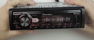
Connection
The Pioneer car radio can be connected in two ways. The first of them will be presented below. The first connection method involves using a standard connector, and the second involves connecting without standard connectors.
Note. It is worth knowing in advance that the use of the second connection method is not supported by car radio manufacturers and the warranty will no longer be valid. In addition, there is a slight chance of making a mistake in the process of connecting the wires.
On the other hand, the second connection method is popular among motorists due to the fact that there is simply no other choice. In particular, if the vehicle does not have an appropriate connector for connection, you have to use this method.
Attention. Even if you use the first connection method, you need to be extremely careful and do everything very carefully
It is first recommended to make sure that the wiring of the terminals on the connector is carried out correctly.
Pioneer car radio connection algorithm
Pioneer instructions for car radio
ISO plugs are an internationally accepted connection standard for all car radios. So, to connect the car radio in the first way you will need:
- Plugs;
- Adapters;
- Insulating tape.
Let's get started:
- We cut the wires from the radio plug or car wiring.
- We connect the car radio according to the color pinout given above.
- All wires are carefully insulated with tape.
Installing contacts according to the ISO standard makes it possible to subsequently install a new pioneer car radio without laying wires. It will be enough to pull out the old radio on the slide, switch the plugs and that’s it.
Instructions for the pioneer car radio
If you have never connected a car radio to your car, you will have to do the following:
- Route the speaker wire for the speakers in accordance with the pinout above.
- Attach the car radio frame to the console panel.
- After installing the frame in the finished slot, the metal petals on the frame are bent (this is done with a screwdriver and thus the frame sits securely in its place).
- We connect the radio to the plugs.
- We insert it into the socket until a characteristic click appears.
- We check the operation of the radio.
When dismantling the car radio, it will be enough to unclench the side lobes.
The above instructions for connecting a Pioneer car radio are not the only ones. Here the process is described in general terms, and for detailed information it is recommended to use not only step-by-step recommendations, but also photos and videos - materials where everything is carefully shown and explained. The cost of installing a car radio with your own hands will be very low, because you will only have to spend money on a couple of plugs and electrical tape.
Installation in the car
Installation of the radio begins with the removal of the decorative plugs covering the mounting socket in the center console. To mount the head unit, metal clips are used, which are held in the instrument panel by bendable antennae. If the car was equipped with a 1 Din-format radio, and you plan to install equipment with increased dimensions, then a box for small items is removed from the console. It is not possible to install a 2 Din standard player on some machines, or the installation of a new console will be required to accommodate the unit.
To install a radio instead of the original equipment, it is necessary to install adapter brackets that allow you to attach the tape recorder to the power frame of the dashboard. Installing a non-standard radio requires the use of a decorative frame that allows you to fit a rectangular front panel into a hole with beveled edges or rounded corners (depending on the type of car). The additional element is installed by hand and does not require modification of standard parts from the machine.
Connecting speakers
Connecting the radio to a car equipped with standard acoustics does not require laying patch cables. The owner will need to directly connect the plugs to the mating connectors on the head unit or use an adapter. If speakers are installed simultaneously with the installation of multimedia equipment, then signal cables will need to be laid. Depending on the design of the car, acoustics are installed in the doors, instrument panel or shelf located behind the back of the rear row of seats.
To connect the acoustics to the head unit, a special-purpose stranded copper wire coated with an elastic insulator is used. On the speaker body there are positive and negative contacts with symbols. The connection diagram for the car radio provides for connecting loudspeakers in compliance with polarity; connecting negative cables into a common bus is prohibited. Since the wires come without a chip, it is necessary to provide a plug that will ensure a reliable connection.
Antenna connection
Once the power cables and speaker patch cords have been connected, the antenna plug should be reinstalled. On some cars, the cable with the connector is folded deep into the instrument panel; the owner needs to pull the cord to the installation site himself. Standard antennas are equipped with frequency filters that eliminate interference and increase the range of signal reception from repeaters. The factory unit is connected using a plug that is installed in the mating socket on the back of the car radio.
If the car is not equipped with an antenna, then many owners connect an active type device that is mounted on the windshield. The built-in amplifier requires power, which is provided by the output in the player's jack, marked AMP or REM. After connection, the junction point is protected with insulating tape. At this stage, the procedure for installing the radio in the car ends; the owner can test the operation of the equipment.