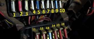
The VAZ 2104 with rear-wheel drive and a station wagon body was produced from 1983 to 2012. The model was constantly improved: electrical equipment was changed, a fuel injection system, a five-speed gearbox and semi-sports front seats appeared. The VAZ 21043 modification was supplemented with a system for cleaning and heating the rear door window. Information on the diagrams is intended for self-repair of cars. Electrical circuits are divided into several blocks for ease of viewing via a computer or phone; there are also files in the form of a single picture with a description of each element - for printing on a printer.
VAZ-2104 diagram (old version)
- block headlights;
- – side direction indicators;
- - accumulator battery;
- – starter enable relay;
- – carburetor electro-pneumatic valve;
- – carburetor microswitch;
- – generator 37.3701;
- – gearmotors for headlight cleaners;
- – electric motor of the engine cooling system fan*;
- – fan motor activation sensor*;
- – sound signals;
- – ignition distributor;
- - spark plug;
- – starter;
- – coolant temperature indicator sensor;
- – engine compartment lamp;
- – oil pressure warning lamp sensor;
- - ignition coil;
- – brake fluid level sensor;
- – windshield wiper gearmotor;
- – carburetor electro-pneumatic valve control unit;
- – electric motor of the headlight washer pump;
- – electric motor of the windshield washer pump;
- – brake light switch;
- – windshield wiper relay;
- – instrument lighting regulator;
- – relay-breaker for alarm and direction indicators;
- – reverse light switch;
- – plug socket for a portable lamp*;
- – cigarette lighter;
- – glove box lighting lamp;
- – mounting block;
- – lamp switches on the front door pillars;
- – lamp switches on the rear door pillars;
- – lampshades;
- – parking brake warning lamp switch;
- – switch for the carburetor air damper warning lamp;
- – tailgate glass cleaner and washer switch;
- – hazard warning switch;
- – three-lever switch;
- – ignition switch;
- – ignition relay;
- – external lighting switch;
- – rear fog light switch;
- – fog light circuit fuse;
- – oil pressure warning lamp;
- – instrument cluster;
- – fuel reserve warning lamp;
- – fuel level indicator;
- – courtesy light for the rear part of the cabin;
- – battery charge indicator lamp;
- – coolant temperature indicator;
- – carburetor air damper warning lamp;
- – parking brake warning lamp**;
- – control lamp block;
- – rear fog light indicator lamp;
- – control lamp for heated rear door glass;
- – brake fluid level warning lamp;
- – voltmeter;
- – speedometer 2104;
- – control lamp for external lighting;
- – indicator lamp for direction indicators;
- – high beam warning lamp;
- – heater fan switch;
- – switch for heated rear door glass with backlight;
- – heater fan electric motor;
- – additional resistor for the heater electric motor;
- – electric motor of the tailgate glass washer pump;
- – rear lights;
- – gearmotor for tailgate glass wiper;
- – pads for connecting to the rear glass heating element;
- – license plate lights;
- – sensor for level indicator and fuel reserve.
A
– headlight units, headlight and tailgate glass cleaners, windshield wiper relay breaker, carburetor electric pneumatic valve control unit;
b
– mounting block and three-lever switch;
c
– rear lights (pin numbering in order from top to bottom);
d
– alarm relay and direction indicators.
Transition from an electromagnetic-thermal relay to an electronic one.
This “barrel” is located under the dashboard of a car. This is an electromagnetic thermal relay. Due to short-term operation (1-2 months), it is recommended to replace it with an electronic one. After this time, it begins to burn or shorts out.
The following are the steps to replace it:
- disconnect the contact terminals;
- We mark each wire with a marker, or use paint to highlight it in different colors;
- contact No. 1 of the electronic relay is connected to the wire with the x sign;
- Contact No. 2 of the electronic relay is connected to the wire marked L;
- contact No. 3 of the electronic relay is connected to the wire marked P;
- Contact No. 4 is ground, we connect it to a separate wire.
All this work must be carried out when using heat shrink.
The replacement of incandescent lamps with LEDs in direction indicators is gaining great popularity due to the fact that incandescent lamps are much inferior to LED lamps in terms of service life and light output.
VAZ 2107 (Lada 2107) rear-wheel drive sedan which was produced in 1982, 1983, 1984, 1985, 1986, 1987, 1988, 1989, 1990, 1991, 1992, 1993, 1994, 1995, 1996, 1997, 1998, 1999, 2000, 2001 , 2002, 2003, 2004, 2005, 2006, 2007, 2008, 2009, 2010, 2011 and 2012 mainly with gasoline engines (injector, carburetor). The VAZ 2105, 2104 models are assembled on a common platform with the 2107, so the design of their blocks is largely the same. In this publication you will find a description of fuses and relays of VAZ 2107, 2105, 2104 with a block diagram and photo examples of execution. Note the fuse responsible for the cigarette lighter. In conclusion, we suggest that you familiarize yourself with the electrical connection diagram of the fuse box.
p, blockquote 1,0,0,0,0 —>
p, blockquote 2,0,0,0,0 —>
Electrical diagram of VAZ 2104
Scheme of VAZ-2104, for cars of early years of production. It is distinguished from the standard circuit by the G-222 generator, 10-pin hazard warning switch, 5-pin relay for direction indicators and hazard warning lights, top dead center sensor of the 1st cylinder, diagnostic block, rear window heating indicator lamp directly in the switch , the absence of a carburetor choke warning lamp, a two-position exterior lighting switch and a three-position steering column light switch.
1 – headlights; 2 – side direction indicators; 3 – battery; 4 – battery charge warning lamp relay; 5 – carburetor electro-pneumatic valve; 6 – top dead center sensor of the 1st cylinder; 7 – carburetor microswitch; 8 – generator G-222; 9 – gearmotors for headlight cleaners*; 10 – electric motor of the engine cooling system fan*; 11 – fan motor activation sensor*; 12 – sound signals; 13 – ignition distributor; 14 – spark plugs; 15 – starter; 16 – coolant temperature indicator sensor; 17 – engine compartment lamp; 18 – oil pressure warning lamp sensor; 19 – ignition coil; 20 – brake fluid level sensor; 21 – windshield wiper gearmotor; 22 – carburetor electro-pneumatic valve control unit; 23 – electric motor of the headlight washer pump*; 24 – electric motor of the windshield washer pump; 25 – diagnostic block; 26 – brake light switch; 27 – windshield wiper relay; 28 – relay-breaker for alarm and direction indicators; 29 – reverse light switch; 30 – plug socket for a portable lamp; 31 – cigarette lighter; 32 – glove box lighting lamp; 33 – mounting block (a jumper is installed instead of a short-circuit relay); 34 – lamp switches on the front door pillars; 35 – lamp switches on the rear door pillars; 36 – lampshades of VAZ 2104; 37 – parking brake warning lamp switch; 38 – rear window cleaner and washer switch*; 39 – alarm switch; 40 – three-lever switch; 41 – ignition switch; 42 – instrument lighting switch; 43 – external lighting switch; 44 – rear fog light switch; 45 – oil pressure warning lamp; 46 – instrument cluster; 47 – fuel reserve warning lamp; 48 – fuel level indicator; 49 – courtesy light for the rear part of the cabin; 50 – battery charge indicator lamp; 51 – coolant temperature indicator; 52 – relay-interrupter for the parking brake warning lamp; 53 – control lamp block; 54 – brake fluid level warning lamp; 55 – rear fog light indicator lamp; 56 – parking brake warning lamp; 57 – voltmeter; 58 – speedometer; 59 – indicator lamp for external lighting; 60 – turn signal indicator lamp; 61 – control lamp for high beam headlights; 62 – heater fan switch; 63 – switch for heated rear window with control lamp*; 64 – heater fan electric motor; 65 – additional resistor of the heater electric motor; 66 – electric motor of the rear window washer pump; 67 – rear lights; 68 – rear window wiper gear motor*; 69 – pads for connecting to the rear window heating element; 70 – license plate lights; 71 – sensor for level indicator and fuel reserve.
Electrical diagram - full view:
Main and auxiliary elements of the electrical circuit
The general circuit of the VAZ 2104 is single-wire. All electrical equipment in a vehicle is connected to each other via one cable - the positive cable. The negative contact is ground or ground, that is, the car body. Components of a car - engine, transmission - can also be used.
All electrical equipment connected via wires can be divided into several groups:
- Working devices. With their help, the start and operation of the machine’s engine is ensured.
- Light and sound alarm.
- Assistive devices. These devices facilitate the use of the vehicle as a whole.
- Equipment to provide more comfortable control.
Working devices include:
- battery;
- generator unit;
- ignition system components;
- devices by which these units are controlled.
The battery in the VAZ 2104 is one of the main elements; it can be classified into all groups of components. The battery powers electrical appliances when the power unit is turned off. But the main task of the device is to provide power to the starter mechanism. The latter is a power electric motor, through which the unit and ignition system are started. When the engine is running, the generator set takes over the functions of the battery.
This unit generates electricity, which is necessary to power all equipment. At increased crankshaft speeds, the generator restores the battery charge that was spent to start the internal combustion engine. If the load on the equipment is too high when many devices are turned on, the generator unit may not be able to cope with its task. The battery helps him by powering the electrical grid, since overload will lead to damage to the generator.
The ignition system in a car is used to generate a spark charge in the cylinders of the power unit. This contributes to the ignition of the combustible mixture. The voltage value in the vehicle's on-board network is 12 volts.
This system includes:
- ignition coil;
- distribution unit or distributor;
- spark plug;
- high voltage wires;
- The lock is the main component that allows energy to be directed to the starter mechanism and ignition system when starting.
Light signaling is designed to illuminate the road surface at night; low and high beam optics are used for this. Using flashlights, you can warn other road users about the maneuvers that the driver plans to make.
We are talking about:
- overtaking;
- turns;
- braking;
- driving in reverse.
Separate headlights are used to indicate dimensions. The steering horn is used as a sound signal. Light signaling also includes the courtesy light in the vehicle interior. All equipment is powered from the battery when the engine is off and from the generator when the engine is running.
Scheme of VAZ-21043 and VAZ-21047 carburetor
1 – headlights; 2 – side direction indicators; 3 – battery; 4 – starter activation relay; 5 – carburetor electro-pneumatic valve; 6 – carburetor microswitch; 7 – generator 37.3701; 8 – gearmotors for headlight cleaners*; 9 – electric motor of the engine cooling system fan; 10 – fan motor activation sensor; 11 – sound signals; 12 – ignition distributor; 13 – spark plugs; 14 – starter VAZ 21047; 15 – coolant temperature indicator sensor; 16 – engine compartment lamp; 17 – low oil pressure indicator sensor; 18 – ignition coil; 19 – low brake fluid level indicator sensor; 20 – windshield wiper gearmotor; 21 – carburetor electro-pneumatic valve control unit; 22 – electric motor of the headlight washer pump*; 23 – electric motor of the windshield washer pump; 24 – reverse light switch; 25 – brake signal switch; 26 – hazard warning and direction indicator relay; 27 – windshield wiper relay; 28 – mounting block; 29 – lamp switches on the front door pillars; 30 – lamp switches on the rear door pillars; 31 – diode for checking the serviceability of the warning lamp for insufficient brake fluid level; 32 – lampshades; 33 – parking brake warning switch; 34 – indicator lamp for insufficient brake fluid level; 35 – signaling unit; 36 – plug socket for a portable lamp**; 37 – glove box lighting lamp; 38 – tailgate glass cleaner and washer switch; 39 – alarm switch; 40 – three-lever switch; 41 – ignition switch; 42 – ignition relay; 43 – econometrician; 44 – instrument cluster; 45 – carburetor air damper closed indicator switch; 46 – battery charge indicator lamp; 47 – indicator lamp for closing the carburetor air damper; 48 – indicator lamp for turning on the direction indicators; 49 – speedometer; 50 – fuel reserve indicator lamp; 51 – fuel level indicator; 52 – instrument lighting regulator; 53 – hours; 54 – cigarette lighter; 55 – fog light circuit fuse; 56 – heater fan electric motor; 57 – additional resistor of the heater electric motor; 58 – electric motor of the tailgate glass washer pump; 59 – rear fog light switch with on indicator; 60 – heater fan switch; 61 – switch for heating the glass of the tailgate with a switch on indicator; 62-external lighting switch; 63 – voltmeter; 64-lamp indicator for turning on external lighting; 65-lamp for high beam headlights; 66 – indicator lamp for insufficient oil pressure; 67 – parking brake indicator lamp; 68 – tachometer; 69 – coolant temperature indicator; 70 – rear lights; 71 – pads for connecting to the heated glass element of the tailgate; 72 – sensor for level indicator and fuel reserve; 73 – courtesy light for the rear part of the cabin; 74 – license plate lights; 75 – rear door glass wiper motor.
Useful: VAZ-2109 diagram
Electrical diagram - full view:
Additional items
Under the hood
Additional headlight wiper fuses (2A rating) protect the motor windings. They are located on the supply wires next to the gearmotors.
p, blockquote 18,0,0,0,0 —>
p, blockquote 19,0,0,0,0 —>
The starter activation relay 113.3747 or 90.3747-10 is located in the engine compartment on the right mudguard.
p, blockquote 20,0,0,0,0 —>
p, blockquote 21,0,0,1,0 —>
In the cabin
The windshield wiper relay (PC-514) is mounted under the panel on the left under the trim.
p, blockquote 22,0,0,0,0 —>
p, blockquote 23,0,0,0,0 —>
The ignition relay and the hazard warning and turn signal relays are installed on the front panel behind the instrument panel. The ignition relay (113.3747-10 or 90.3747-10) and the hazard warning and turn signal relays (23.3747 or 231.3747) have a bracket for direct mounting on the body.
p, blockquote 24,0,0,0,0 —>
p, blockquote 25,0,0,0,0 —>
The fog lamp fuse is located in the gear shift compartment, not far from the radio.
p, blockquote 26,0,0,0,0 —>
p, blockquote 27,0,0,0,0 —>
Scheme for VAZ-2104 injector
1 – electric motor of the engine cooling system fan; 2 – mounting block; 3 – idle speed regulator; 4 – electronic control unit; 5 – octane potentiometer; 6 – spark plugs; 7 – ignition module; 8 – crankshaft position sensor; 9 – electric fuel pump with fuel level sensor; 10 – tachometer; 11 – control lamp “CHECK ENGINE”; 12 – car ignition relay; 13 – speed sensor; 14 – diagnostic block; 15 – nozzle; 16 – adsorber purge valve; 17, 18, 19 – injection system fuses; 20 – ignition relay for the injection system; 21 – relay for turning on the electric fuel pump; 22 – intake pipe electric heater relay; 23 – electric heater of the intake pipe; 24 – intake pipe heater fuse; 25 – oxygen concentration sensor; 26 – coolant temperature sensor; 27 – throttle position sensor; 28 – air temperature sensor; 29 – absolute pressure sensor;
- A – to the “plus” terminal of the battery;
- B – to terminal “15” of the ignition switch;
- P4 – relay for turning on the fan motor.
Installing an electronic BSZ instead of a contact one
Today it is very rare to find a “seven” with contact ignition. With the arrival on sale of switches, distributors and coils for electronic spark generation systems, owners of classics began to massively re-equip their cars.
What is included in the BSZ kit
The process of converting a contact system into an electronic one is quite simple, and also inexpensive. The cost of an electronic ignition kit for a VAZ 2107 is about 2,500 rubles. It includes:
- transistor switch type 3620.3734 with connector;
- coil 27.3705;
- contactless distributor type 38.3706;
- connecting wires.
In addition, you will need spark plugs (preferably new ones) with a gap of 0.7–0.8 mm and a set of high voltage wires. Coil type B-117A (used in a contactless system) is not suitable for electronic ignition . Its characteristics do not correspond to those of other equipment in the circuit.
Video: review of BSZ elements for “classics”
Required Tools
To complete the work you will need:
- 8, 10 and 13 mm wrenches;
- screwdriver with a Phillips blade;
- drill;
- spark plug key;
- 36 mm wrench or with a ratchet mechanism for turning the crankshaft;
- self-tapping screws;
- pliers.
Work order
Work on converting the ignition system into a contactless one is carried out in the following order:
- Disconnect the terminals from the battery. We remove the battery and put it aside.
- Remove the high voltage caps from the distributor cap and from the spark plugs.
- Using a special wrench, unscrew all the spark plugs. We screw new ones in their place.
Video: installing BSZ on a “classic” VAZ
Brake system VAZ 2104
- Brake fluid level sensor built into the expansion tank cap;
- Electronic mounting block in the engine compartment with terminal “A” to the generator;
- Ignition relay with negative terminal to ground;
- Ignition switch on the steering column;
- Indicator lamp on the instrument panel indicating low brake fluid level;
- Indicator lamp for activated parking brake.
Removal and Replacement Guide
If you do not know how to remove and disassemble the mounting device or safety elements and how to replace the old unit with a new one, then we will consider each instruction in turn.
Changing fuses yourself
Before you begin replacing the safety devices located in the main unit, you must turn off the ignition and battery terminals under the hood.
The replacement procedure is carried out as follows:
- Find the installation location of the device. There are latches on the plastic cover of the block; press them. After removing the cover, you will be able to see a diagram printed on the reverse side, which indicates the location and purpose of all used elements.
- Then you need to identify which device has failed and needs to be replaced. Sometimes a breakdown can be determined visually - the component itself may be burnt out, sometimes a broken thread is clearly visible in it.
- Under the cover of the device you will see tweezers, which can be used to remove the device. If you don't have tweezers, you can use pliers.
- Remove the burnt out element and replace it with a new one, then replace the cover and connect the battery terminals (video filmed and published by the AVTOCLUB_22 channel).
Replacing fog lamp fuses
If the fog optics break down, you should first diagnose the operation of the device. The component is located inside the car.
To check and replace, follow these steps:
- First you will need a Phillips screwdriver, use it to remove the two switches located in the middle of the console, near the audio system.
- Using a screwdriver, you will need to press out two fasteners.
- Then remove the plastic insert.
- You can now remove the fuse housing. Remove the protective cover of the device and replace the part with a new one.
1. Remove the two switches with a screwdriver.
2. Press on the pad fasteners.
3. Remove the insert and remove the device.
Changing the fuse box
Removing and replacing the block with components is done as follows:
- First, open the engine compartment of your car and remove the air filter housing. Unscrew the nuts that secure the housing using a Phillips screwdriver.
- Then under the device you will be able to see a plug with cables connected to the device, you need to unplug it. The product body itself is marked in colors; it corresponds to the color of the connected connectors. By taking these plugs into account, the need to label cables can be avoided.
- After this, you should climb into the vehicle interior and remove the shelf, which is located under the control panel. After this, unscrew the bolts that hold the glove box housing.
- Next, disconnect the plug with cables connected to the connectors directly on the device. Once you do this, you will be able to see the color coding.
- Using a wrench, remove the bolts that secure the block itself. Please note that the outermost screw on the case is hidden, so you will not be able to see it immediately.
- At the end, remove the block with the devices, now the device can be replaced. Installation of a new device, as well as assembly of components, is carried out in the reverse order.
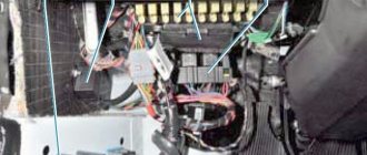
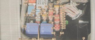
The mounting fuse block contains some electrical control elements of a VAZ car and most fuses that protect electrical circuits from short circuits and overloads. It is located in the engine compartment on the left side, immediately on the metal partition between the engine compartment and the cabin. Here is the photo (top left):
Engine Fan Circuits
Examination
The easiest way to test a switch is to try replacing it with a known good one. But this can only be done if a working switch is at hand. It is not advisable to buy a new unit just to test the operation of the old one. There is a cheaper and not particularly complicated way. To test the switch, you only need a standard set of keys and a test lamp. This is enough to verify the presence or absence of pulses supplied to the ignition coil. Before checking the switch, make sure that “plus” is supplied to it and the ignition coil. Also check the connection contacts of the Hall sensor and the functionality of the sensor itself. Checking the VAZ 2107 ignition switch is performed as follows:
- turn off the ignition;
- unscrew the nut on the ignition coil and disconnect the brown wire marked “K” (the wire goes to connector “1” on the switch);
- connect a test lamp to the gap between the wire terminal and the coil terminal;
- turn on the ignition;
- turn the key and start the starter.
A flashing light indicates a working switch. If the lamp does not light, the switch needs to be replaced.
Replacing a VAZ 2107 switch
To replace the switch, you must complete the following steps:
- turn off the ignition;
- disconnect the wire block from the switch connector;
- unscrew the fastening nuts;
- remove the old switch and put a new one in its place;
- tighten the fastening nuts;
- connect the wire block to the connector.
Scheme for switching on headlights and fog lights
1 — block headlights; 2 — mounting block 2104; 3 — headlight switch in a three-lever switch; 4 — external lighting switch; 5 — rear fog light switch; 6 — rear lights; 7 - rear fog light circuit fuse; 8 — fog light indicator lamp, located in the indicator lamp block; 9 — indicator lamp for high beam headlights, located in the speedometer; 10 — ignition switch; P5 - headlight high beam relay; P6 - low beam headlight relay; A - view of the headlight plug connector: 1 - low beam plug; 2 — high beam plug; 3 — ground plug; 4 — side light plug; B - to terminal 30 of the generator; B — terminals of the rear light printed circuit board (numbering of terminals from the edge of the board): 1 — to ground; 2 — to the brake light lamp; 3 — to the side light lamp; 4 — to the fog light lamp; 5 — to the reversing light lamp; 6 - to the turn signal lamp.
Turn relay: the basis of car light signaling
All vehicles must be equipped with intermittent turn signal lights. Correct operation of turn signals is ensured by special relay-interrupters - read all about these devices, their types, design and operation, as well as selection and replacement in this article.
Sources:
https://tuning-vaz2106.ru/5/rele-povorotov-vaz-2104-gde-naxoditsya-zamena-rele-povorotnikov-na-vaz-klassika-2104-2105-2106-2107-remont-avtomobilej-svoimi- rukami-video.html https://yubus.ru/rele-povorotov-vaz-2107-gde-nahoditsja
Fuse and relay block VAZ-2104
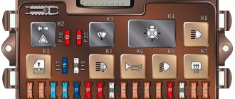
On newer “sevens” a block with 17 fuses and 6 relays is installed. VAZ 2107 fuses on the “new” unit protect the following electrical circuits and devices:
- Reversing lamps, heater fan, rear window defroster warning lamp and relay, rear wiper motor and rear washer pump.
- Electric motor for front wipers.
- Reserve socket.
- Reserve socket.
- Power supply for heated rear window.
- Clock, cigarette lighter, power socket “carrying”.
- Signal and radiator fan.
- Turn signal lamps in emergency mode.
- “Fog lights” and a relay that regulates the voltage of the on-board network.
- Instrument panel lamps.
- Brake light bulbs.
- Right high beam headlight.
- Left high beam headlight, high beam warning lamp.
- Side lights (rear right, front left), license plate and engine compartment lighting.
- Side lights (rear left, front right), glove compartment and cigarette lighter lamps.
- Low beam (right lamp).
- Low beam (left lamp).
The block relays perform the following functions:
- Heated rear window relay.
- Headlight cleaner and washer relay.
- Signal relay.
- Cooling system electric fan relay.
- High beam relay.
- Low beam relay.
How to replace fuses yourself
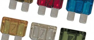
If a breakdown is detected in the fuses, then the best option would be to immediately disassemble the unit and replace the failed component. The process of replacing fuses is quite simple and does not require special skills. After all, it’s enough just to remove the old fuse and install a new one (the price of new fuses is quite reasonable and fluctuates around 50-100 rubles for 10 pieces).
If the decision is made to replace the fuses, it is necessary to replace everything, since if you leave the old ones and install several new ones, a voltage drop may occur and all the fuses will blow. It is also necessary to fully ensure that their location is correct according to the diagram and output current.
Based on all of the above, we can conclude that the fuses in the domestically produced VAZ-2104 car are quite an important component, which literally saves the entire car from any unwanted breakdown, and in which case it protects its owner from significant problems.
It should also be said that the VAZ-2104 and its fuses are practically no different from other models, except for the location. Every car, be it a modern sports car or an old classic, needs careful care. In this regard, in order to avoid serious breakdowns, maintenance should be carried out in a timely manner and even the most minor breakdowns should not be neglected.
Car modifications
VAZ-2104 . The basic version of the station wagon, with a carburetor engine from the VAZ-2105, 1.3 liters and 64 horsepower. Equipped with a 4-speed gearbox.
VAZ-21041 . A prototype of a station wagon, it was equipped with a carburetor engine from a VAZ-2101, with a volume of 1.2 liters and a power of 62 hp. Just like the base model, it was equipped with a 4-speed manual transmission.
VAZ-21042 . Export version, the steering wheel was located on the right. The car also received a carburetor engine from the VAZ-2103, with a volume of 1.5 liters and a power of 72 hp.
VAZ-21043 . The car was equipped with electrics and interior from a VAZ-2107, some copies had a VAZ-2106 interior. The carburetor engine was borrowed from the VAZ-2103. The gearbox was either 4 or 5 speed.
VAZ-21044 . An export model, equipped with a 1.7-liter VAZ-2107 engine with mono-injection, as well as a 5-speed gearbox.
VAZ-21045 . The export version with a 1.8-liter engine did not enter mass production.
VAZ-21045D . It was produced in small series since 1999, equipped with a VAZ-341 diesel engine with a volume of 1.52 liters and a power of 50 horsepower. The gearbox is 5-speed.
VAZ-21047 . A prototype with an engine starting from a penny. An improved version of the “Four”, it was equipped with a VAZ-2107 interior and a VAZ-2103 carburetor engine with a volume of 1.5 liters and a power of 72 hp. The gearbox was 5-speed. On export versions, the radiator grille was installed from the VAZ-2107.
VAZ-21048 . Diesel station wagon, with a 1.77-liter VAZ-343 engine. The gearbox is 5-speed.
VAZ-21041i . A car equipped with a VAZ-21067 injection engine. volume 1.6 liters. The gearbox is 5-speed. The electrical equipment and interior are from a VAZ-2107 car, and the front seats are from the Izhevsk hatchback IZH-2126.
VAZ-21041 VF . The interior, electrics and front seats are the same as the previous modification; the radiator grille is also borrowed from the VAZ-2107. It was equipped with a 1.5 liter injection engine from the VAZ-2103 and a 5-speed manual transmission.
How to check if a fuse is broken
Before any procedure related to fuses, it is necessary to check whether it is broken or blown, as this happens quite often. One of the simplest, but not the most reliable, is the option with a visual assessment of the fuse.
Another, more reliable method would be to check using a special tester, which will make sure that the fuse is working properly or broken. But what to do in case of breakdown? In this situation, there is only one way out - replacing the fuse.
Replacing the fog light fuse
Proper operation of the fog lights is ensured by a fuse, which is located separately from the fuse box.
It is located under the console center panel, next to the button for turning on the fog lights on the panel next to the radio. To carry out inspection or replacement work, perform the following sequence of operations:
- Turn off the vehicle's power.
- You need to use a screwdriver to disconnect the switches from the console in the place where the radio is installed, ensuring free access.
- Pull out the plastic insert on the console by squeezing it with a screwdriver to gain access to the fog lamp fuse housing.
- Remove the housing and check or replace the fuse link.
- Reassemble all the elements and switches in the reverse order to make sure the fog lights are working.
