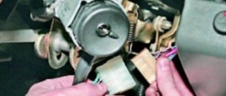
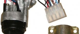
Installing the "Start" button
Some Kopek owners tune the ignition system of their cars by installing a “Start” button instead of the standard ignition switch.
But what does such tuning give? The essence of such modifications is to simplify the process of starting the engine. With a button instead of a lock, the driver does not need to poke the key into the lock, trying to get into the cylinder, especially without the habit and without lighting. In addition, you don’t need to carry the ignition key with you and worry about losing it. But this is not the main thing. The main thing is the opportunity to enjoy the process of starting the engine with one press of a button, and also to surprise the passenger with this.
Using this button, you can start the engine without the ignition switch and key.
In automobile stores you can purchase a kit for starting a power unit from a button for about 1,500–2,000 rubles.
A kit for starting an engine with a button can be purchased at auto stores.
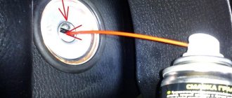
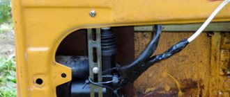
But you can save money and assemble an analogue yourself. To do this, you only need a toggle switch with two positions and a button (not recessed), which will fit the size of the ignition switch housing. The simplest connection diagram is shown in the figure.
The toggle switch and button can be installed in any convenient place
Thus, by turning on the toggle switch, we supply voltage to all devices and to the ignition system. By pressing the button, we start the starter. The toggle switch and the button itself, in principle, can be placed anywhere, as long as it is convenient.
As you can see, there is nothing complicated either in the design of the VAZ 2101 ignition switch or in its repair. If it breaks, you can easily repair or replace it.
Pinout of the ignition switch VAZ-2101 VAZ-2107
Electrical diagram of the VAZ-2105 and VAZ-2104 cars.
The ignition switch for these cars is located to the left of the steering column. It is fixed directly to it using two fixing bolts. The entire mechanism of the device, except for the upper part in which the keyhole is located, is hidden by a plastic casing.
On the visible part of the ignition switch housing, special marks are applied in a certain order, allowing inexperienced drivers to navigate the lock activation mode when the key is in the hole:
- “ ” – a mark indicating that all systems, devices and instruments that are turned on using the lock are turned off (this does not include the cigarette lighter, interior lighting, brake light, and in some cases the radio);
- “I” is a mark informing that the vehicle’s on-board network is powered from the battery. In this position, the key is fixed independently, and electricity is supplied to the ignition system, to the electric motors of the heater and windshield washer, instrumentation, headlights and light signaling;
- “II” – engine start mark. It indicates that voltage is applied to the starter. The key does not lock in this position. If you release it, it will return to the "I" position. This is done so as not to subject the starter to unnecessary loads;
- “III” – parking mark. If you remove the key from the ignition in this position, the steering column will be locked with a latch. It can only be unlocked by inserting the key back and turning it to position “0” or “I”.
The ignition switch has five contacts and, accordingly, five terminals, which are responsible for supplying voltage to the desired unit. All of them are numbered for convenience. Each pin corresponds to a wire of a certain color:
- “50” – output responsible for supplying current to the starter (red or purple wire);
- “15” – terminal through which voltage is supplied to the ignition system, to the electric motors of the heater, washer, and instrument panel (double blue wire with a black stripe);
- “30” and “30/1” – constant “plus” (pink and brown wires, respectively);
- “INT” – external lighting and light signaling (double black wire).
Color gradation
To correctly connect the contacts on the back side, you need to know the colors of the wires. Each of the chips comes with a cable with insulation of a personal shade. We recommend focusing on the diagram:
- pin 50 – contacts the red wire connected to the starter;
- pin 30 – pink contact;
- pin 30/1 – brown cable;
- pin 15 – blue with a dark stripe is in contact with the heater, ignition, etc.;
- INT pin – black cable, responsible for starting the head optics and operating the dimensions.
After all the wiring is connected, we can reconnect the battery terminals and check the functionality. We start the ignition in each position one by one, testing the performance of the devices.
Self-replacement
Checking the ignition switch on a VAZ 2108, 2109, 21099 car
If there is a specific problem with the lock, jamming or general breakdown, a complete replacement of the device assembly may be necessary. To do this, you need to remove the old one, then install the new one in the socket and correctly connect all the wires to the terminals.
The main condition is to do everything slowly and remember the actions taken. This is especially true for the correct connection of wires.
To replace the ignition switch, you must follow the following sequence of actions:
- Disconnect ground from the battery. If this is not done, a short circuit will occur when the device is removed.
- Set the lock to the “zero” position.
- Cover it with a special decorative plastic covering.
- After this, you should unscrew the fastenings of the device itself.
- Find the technological window. It is located where the lock is secured. You need to press the locking corkscrew that holds the element body and pull the lock out of the socket.
- The wires that are directed to the contact group of the device must be disconnected.
- If only the mechanical part of the device needs to be replaced, then use a screwdriver to remove the retaining ring, remove the group of contacts and install it in the new device.
- Install a new lock in the slot.
- Tighten the fasteners on it.
- Connect all cables to the ignition switch terminals. To do this, it is recommended to use a special scheme.
- After this, install the decorative cover on the steering column.
- Screw the fastenings of the cover.
- Connect the ground cable to the battery.
- Check the quality of the work performed, why try to start the car.
Ignition switch circuit
As can be seen from the description, you can remove the lock without any problems. If you only need to replace the contact connection point, then experts still recommend dismantling the entire device. This way the replacement task can be greatly simplified.
In addition, you need to have a good understanding of how to connect all the electrical wires. Usually the connection diagram itself is displayed on the device box:
- First, you need to use an awl or a screwdriver to remove the retaining ring that holds the contact group in the body of the device itself. In this case, only experience and skill will help, since the operation is quite problematic.
- Change the old contact group by installing a new one in its place.
- Install the retaining ring into the special groove on the body.
- Make all wire connections.
- Place the decorative cover in place and secure it.
- Next, connect the battery and ground.
- Check for normal operation.
Removing the device from the car
In order to know how to remove the ignition switch on a VAZ-2107 car, you need to have an understanding of not only its functionality, but also its structure. This element in Zhiguli consists of two parts - a switching mechanism and a contact board
The importance of both components is also significant because if one fails, the entire device will not work. You may need to remove the lock for various reasons:
- the device does not work, although the key is not broken;
- jammed key when the steering wheel is locked;
- the broken key remained a secret;
- the owner lost his car keys, etc.
Step-by-step dismantling of the lock:
- Remove the decorative cover of the steering shaft.
- De-energize the vehicle by disconnecting the negative terminal of the battery.
- Disconnect the wire bundle from the lock.
- Insert the key and turn it to the zero position - “Off”. During this, you need to turn the steering wheel slightly left and right to move the locked steering shaft to the required position and disable the anti-theft mechanism.
- Loosen the lock fastening by removing the screws securing the steering shaft bracket.
- Use an awl, a small screwdriver or strong wire to press out the fastener.
- Pull the lock out of its seat.
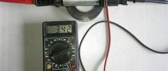
After this, you can replace the non-working device with a purchased new one, repair the group of contacts, the cylinder. But first, it would be better to check the supposedly broken element for functionality, maybe it’s not the problem. To check the ignition switch you will need an ohmmeter, also called a multimeter.
In turn, connect the terminals of the device to the lock terminals that correspond to the specific position of the key in it. Resistance tending to zero indicates that the contact group is in good working order. If the resistance is greater than zero, the contacts are burnt or oxidized.
In order to replace a group of lock contacts, it is enough to: remove the locking ring from its base, remove the group itself from the device body and replace it with a new one.
If you don’t want to do this yourself, you can always turn to specialists for help.
Why is it needed?
Self-replacement of the ignition switch of a VAZ 2110
As soon as cars appeared, there was no ignition key, and the engine was started using a curved element for the engine, which was quite large and stuck in the front or back of the car. Thus, it turned out that the engine was started manually in the literal sense.
Now this function has been inherited by the starter, which turns the internal combustion engine by the flywheel - a large flat disk with teeth. This disc is located between the engine and the clutch.
This does not happen without the participation of battery power, of course.
The ignition switch is a device that, when turned on, ensures the supply of electric current from the battery to the traction relay. This is a kind of first push to move the vehicle. Therefore, the ignition switch is an important element, and when it breaks, replacement cannot be avoided, and in order to install a new one, you need to remove the old one.
Second phase
We remove the dashboard.
To simplify the work of laying wires, it is better to remove the dashboard completely. To do this, you need to pierce the points that are located next to the screws securing the front panel. Find the location of the wires under the dashboard and in the glove compartment. It is through them that the wires will be laid.
Dismantling old wires.
At this stage of the work, you need to remove the old power window wires and lay new ones. Next you need to connect them to the drive.
Connecting the activator wires.
Along with connecting the activator wires, you need to insulate them and lay them inside the door. In order for them to be secured, it is better to secure them to the door structure using the same electrical tape.
Laying wires.
After the work has been done, you need to push the wires on one side under the dashboard, on the other side into the glove compartment. Such work cannot always be achieved the first time; it is at this stage that you need to show skill and dexterity.
Installation of the pass-through tube.
You can install the pass-through tube into the rack on both sides using a screwdriver
This must be done carefully so as not to damage the rubber tube itself.
Connecting wires to the connector.
Next, a fuse is attached to the connector and connected to the central locking power supply. All this is installed under the dashboard.
Connecting the central locking wire to the housing.
The negative wire of the central locking must be connected to the car body. The positive wire is connected to fuse No. 1 on the battery side.
Checking the functionality of the central locking system.
After you have connected the battery, check the functionality of the mechanism - both its mechanical and electrical parts. The movement of the rods should be smooth and easy.
Restoration of the dashboard and door trim.
After making sure that everything is working properly, install the dashboard and side door trim in their place.
Video shows how to install central locking:
Ignition switch VAZ 2107
The ignition switch (IZ) of the VAZ 2107 is an electromechanical type device. It is located under the dashboard and is attached to a bracket welded to the left side of the steering column shaft.
Purpose of the ignition switch
The main function of the protection system is to synchronize electrical systems when starting and operating the vehicle. When you turn the key in the lock, current begins to flow to the starter solenoid relay, to the ignition system, to instrumentation and lighting devices, heater, etc. When the ignition switch is turned off, most of the electrical equipment is completely de-energized, protecting the battery from discharge. At the same time, the anti-theft mechanism is activated, blocking the steering wheel at the slightest turn.
The key in the ZZ VAZ 2107 can occupy four positions, three of which are fixed:
- 0 — “Disabled.” Electrical wiring is de-energized. The key cannot be removed from the lock; the anti-theft mechanism is disabled.
- I - “Ignition”. The engine spark system, generator excitation, instrumentation, exterior lighting, windshield wiper blades, heater and turn signals are included. The key cannot be removed from the lock; the anti-theft mechanism is disabled.
- II - “Starter”. Current is supplied to the starter. The position of the key is not fixed, so it must be forcibly held in this position. It cannot be removed from the lock.
- III - "Parking". Everything is turned off except the sound signal, side lights, windshield wiper blades and interior heating stove. When the key is removed from the lock, the anti-theft mechanism is activated. When turning the steering wheel in any direction, it will be locked. To confirm the locking, a sound signal will be heard - a click. To disable the anti-theft system, you need to insert the key into the lock, set it to position “0” and smoothly turn the steering wheel in any direction until it unlocks.
When descending a Zhiguli from a mountain or driving at neutral speed, you must not turn off the engine and remove the key from the lock. Such actions will lead to jamming of the steering wheel and the creation of an emergency situation on the road due to difficulties in controlling the car.
Ignition switch connection diagram
On the new VAZ 2107, all the wires going to the ignition switch are collected into one plastic chip, which is not difficult to connect. To disable the lock, you simply need to remove this chip. If the wires are placed on the contacts separately, the connection should be made according to the following scheme:
- the red wire (starter) is connected to pin 50;
- to pin 15 - double blue wire with a black stripe (ignition, heater, instruments on the front panel, heated rear window);
- to pin 30 - pink wire (battery plus);
- to pin 30/1 - brown wire (battery plus);
- to the INT contact - black wire (dimensions, rear brake lights and headlights).
The ignition switch of the VAZ 2107 is connected according to a scheme that is universal for all classic VAZ models.
Ignition switch device
The VAZ 2107 ignition switch is a cylindrical body that contains a cylinder and a contact mechanism, with a protrusion for fixing the steering wheel. At one end of the cylinder there is a recess for a key, at the other there are contacts for connecting electrical wiring. Each key is individual, which provides an additional guarantee against theft. The lock consists of two parts connected by a leash. In the upper part there is a cylinder (locking device), in the lower part there is a contact group.
The lock
The ignition switch has two tasks:
- the main one is rotation of the movable disk of the contact device;
- additional - steering wheel lock when the ignition is off.
The locking is carried out using a movable locking pin, which, when turning the key clockwise, is partially retracted inside the lock body. When the key is rotated in the opposite direction, the finger extends, and when the key is pulled out, the finger fits into a special recess in the steering column. At the same time, a loud click is heard.
To turn, use a leash that:
- ensures rotation of the movable disk of the contact mechanism;
- fixes the lock in the desired position using holes, balls and springs.
Ignition switch contact mechanism
The contact group of the lock consists of two parts:
- movable disk with conductive plates;
- a fixed plastic block in which electrical wiring contacts are fixed, having special protrusions at the point of contact with the movable disk.
When the key is turned, the plates on the disk close or open the necessary contacts on the block, turning on or off the corresponding components and mechanisms.
Lock device
The integrated module is a cylindrical design that has a side projection for the integrated steering clamp. When the locking pin is switched to closed mode, this option becomes part of the anti-theft system. The lock prevents the steering wheel from turning.
The two ends of the cylindrical product are functional, therefore, on one side the wiring diagram is connected to the VAZ-2107 ignition switch, and on the other side there is a cylinder for the key. Additional protection is the uniqueness of the “secret”, which requires the use of an original key/lock pair to prevent unauthorized access to the vehicle’s electrical system.
The engineers composed the 3Z from two main elements, one of which is the switching mechanism, and the second is the contact board.
Critical faults can occur in both parts. However, most of them are considered beyond repair. Restoration work mainly involves replacing damaged elements. It is also practiced to completely replace the assembly.
How to remove the ignition switch on a VAZ-2107 if it is locked?
There may be cases when it is impossible to turn the larva either by hand or with a tool. It is possible for the key to break when part of the bit remains inside the well. In both cases, the owner needs to remove the device from the car.
First dismantling option:
- Remove the steering wheel from the shaft. The steering wheel is secured with a 24 mm wrench nut, which should not be unscrewed completely. Removing the steering wheel from the splines is done by supporting the legs and striking the forearms. After removing the part from the splined part of the shaft, the nut is completely unscrewed.
- Remove the protective plastic steering column cover secured with Phillips screws.
- Unscrew the screws securing the lock.
- Press the pressure plate with a thin tool, which will slightly unlock the part. The pressure is applied through the slot on the left side of the lock. Pressing the latch will allow you to slide the lock body towards you.
- Use a hammer to hit the plate on the right to rotate the lock around its axis. This will guarantee against the retainer coming back.
- Using a hammer and chisel, break the plate. Apply blows carefully so as not to damage the steering column switch block.
- After removing the plate, the locking rod installed in the two eyes will become visible. One of the eyes is easily visible through the hole.
- Break the eyelet with a chisel or flathead screwdriver.
- Press the plate again through the slot on the left and pull it up. It should move 10-12 mm.
- Using a hammer, strike the lock body (in the area where the plug is installed) and pull it off the shaft.
Second option:
- After the latch is recessed through the slot on the left side of the lock, you need to pull the lock out to the maximum distance.
- On the right side of the lock there is a platform with text and a number. A wedge (screwdriver) is inserted under it.
- After this, the area with the inscriptions is cut off with an impact screwdriver or chisel.
- Use a screwdriver to push the lock pin through the hole and remove the lock from the shaft.
The third method is to destroy the castle with a sharp jerk:
- One person sits in the driver's seat, the second in the passenger seat.
- It is necessary to sharply jerk the steering wheel at the same time, which will cause the destruction of the clamp.
- After this, the lock is removed using the usual method. It is worth noting that only late-release locks can be broken with a jerk; products from the USSR era are more difficult to break this way. In addition, there is a risk of damage to the steering components.
There are other methods for removing jammed ignition switches on a VAZ 2107 - cutting the body, turning or drilling the cylinder, and others. The final choice of dismantling method remains with the car owner.
The technique for removing a jammed device is demonstrated in a video from the Region 4253 channel.
Installation of silent locks on Classic
We will replace standard classic door locks with silent chisel locks (VAZ 2108,09,10,11...). We will change ONLY REAR LOCKS!!!
For this we need:
- Internal lock VAZ 2108 - 2 pcs. (left and right)
- Set of silent locks (“chocolate bars”). - 1 PC. (the set must include 2 locks)
- Bolts for fastening locks (look similar to those that secure door hinges on classics) – 4 pcs.
- Tools:
- Drill and, accordingly, drills for it (8.4)
- File or needle file – Metal saw – Old castle
- Cable (from the lock to the internal “hook” of opening the door) - 1.5-2 meters
- Children's set "CONSTRUCTOR", a couple of parts from it... (a rod and 4 square plates for tensioning the cable will be useful to us)
- Aluminum plate or piece of dense plastic about 2 mm thick 10*6cm - 2 pcs.
- A familiar welder or thread cutting kit...
Let's get started...
On a new, just purchased, INNER lock, we saw off 2 parts:
In the right picture this is part 1 and 2
Next, we look for the PIN and also saw it off so that it falls out, and in its place there is a HOLE!!!
This can be seen better here:
There is a hole in the place of the pin, and in the hole there is a cable fastened with plates from a children's set. This is done so that the cable has an adjustable length)
Insert the cable into the hole formed. We “hook” our “hook” with the other end of the cable. After all, we will need to get out of the car... or rather, not us, but the passengers.
Next, we remove and slightly unclench the BLACK spring, if desired, you can remove it altogether, but I would leave it, you never know, it will come in handy...
Next, take a drill with drill number 4 and drill a hole (the red hole in the picture is opposite the thread for attaching the lock... insert a bolt into it (the red hole in Fig. 5), a rod (blue part) onto the bolt and screw a nut onto the bolt (it’s bad, but it is seen)
Next, remove the lock from the door of our car. We remove the rod from the internal “hook” of opening the door, and we can throw it away))), we will no longer need it. Where this rod is attached to the lock there is a rubber bushing; we carefully remove this bushing and place it on our updated internal lock (more details in Fig. 4, above and to the left of the inscription Spring).
- Next, remove the External “Handle” for opening the door.
- We take a piece of aluminum or hard plastic and a metal saw in our hands and make the following part (we make holes with a drill number 4):
We “disassemble” our door handle (we move the axis of rotation on the handle a couple of cm back) and put the RED
hole, don't mix it up. We put it on so that it rests against the moving part of the handle and moves along the axis with it.
You need to put a bolt into the blue hole, not very large, 1-2 cm (later we will put the rod on it from Fig. 4.).
In principle, the inside is ready.
Let's move on to the outside.
We take a drill, but with a drill number 8, and drill out the hole from the old lock (in the picture on the top right) so that the sleeve of the NEW lock fits in, but does not hang out. And if it dangles, then leave it like that, let it dangle.
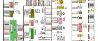
Electrical diagram of VAZ 21074
In VAZ 21074 cars, electrical energy is delivered to consumers using a single-wire circuit: the “positive” terminal of each electrical device is powered from a source, the “negative” terminal is connected to “ground,” i.e., connected to the vehicle body. This solution simplifies the repair of electrical equipment and slows down the corrosion process. All electrical appliances of the car are powered from the battery (with the engine off) or the generator (with the engine running).
The wiring diagram of the VAZ 21074 injector contains an ECM, an electric fuel pump, injectors, and engine control sensors
Wiring diagram VAZ 21074 injector
The injection versions of the “Seven” released from the factory assembly line have the following indices:
- LADA 2107–20 - in accordance with the Euro-2 standard;
- LADA 2107–71 - for the Chinese market;
- LADA-21074–20 (Euro-2);
- LADA-21074–30 (Euro-3).
The injection modifications of the VAZ 2107 and VAZ 21074 use an ECM (electronic engine control system), an electric fuel pump, injectors, control sensors and monitoring engine parameters. As a result, there was a need for additional under-hood and interior wiring. In addition, the VAZ 2107 and VAZ 21074 are equipped with an additional relay and fuse box located under the glove compartment. The additional unit is supplied with wiring that supplies:
- fuses: main relay power circuits;
- controller constant power supply circuits;
- electric fuel pump relay circuits;
- The main thing;
Additional fuse and relay block VAZ 2107 injector located under the glove compartment
Providing electricity
The G7 is responsible for providing consumers with electricity:
- Battery voltage 12 V, capacity 55 Ah;
- generator type G-222 or 37.3701;
- voltage regulator Ya112V, which automatically maintains the voltage within 13.6–14.7 V.
Diagram of the power supply system for the VAZ 21074 injector includes a generator, battery and voltage regulator
Engine starting
The starting system in the VAZ 21074 is a starter and ignition switch powered from the battery. There are two relays in the starter circuit:
- auxiliary, which supplies power to the starter terminals;
- retractor, due to which the starter shaft engages with the flywheel.
The starting system in the VAZ 21074 is a battery-powered starter with a relay and an ignition switch.
Ignition system
In early versions of the seventh VAZ model, a contact ignition system was used, which included:
- ignition coil;
- distributor with contact breaker;
- spark plug;
- high voltage wiring.
The VAZ 21074 contact ignition system consists of a coil, distributor, spark plugs and high-voltage wires
In 1989, the so-called contactless ignition system appeared, the circuit of which included:
- Spark plug.
- Distributor.
- Screen.
- Hall Sensor.
- Electronic switch.
- Ignition coil.
- Mounting block.
- Relay block.
- Key and ignition lock.
In 1989, a contactless ignition system appeared, to the circuit of which a Hall sensor and an electronic switch were added
“Sevens” with injection engines use a more modern ignition circuit. The operation of this circuit is based on the fact that signals from the sensors are sent to the ECU (electronic control unit), which, based on the received data, generates electrical impulses and transmits them to a special module. After this, the voltage increases to the required value and is supplied to the spark plugs through high-voltage cables.
In injection "sevens" the operation of the ignition system is controlled by the electronic control unit of the ECU
Outdoor Lighting
The external lighting system includes:
- Block headlights with dimensions.
- Illumination of the engine compartment.
- Mounting block.
- Glove compartment lighting.
- Instrument lighting switch.
- Rear lights with dimensions.
- Illuminated numbers.
- Exterior lamp switch.
- External lighting indicator lamp (in the speedometer).
- Ignition.
The VAZ 21074 external lighting connection diagram will help in troubleshooting headlights and tail lights
Auxiliary equipment
Auxiliary or additional electrical equipment of the VAZ 21074 includes:
- electric motors: windshield washer;
- windshield wiper;
- heater fan;
- radiator cooling fan;
The connection diagram for windshield wipers uses:
- Gearmotors.
- ED headlight washer.
- Mounting block.
- Egnition lock.
- Washer switch.
Windshield wiper motors drive a trapezoid that moves the wipers across the windshield
Failure of the main vehicle systems
The reason for the sudden failure of many components of the VAZ 2107 car may be damage and failure of electrical wiring elements.
The most common wiring failures are listed below:
- A common defect is a blown fuse link caused by a circuit overload or short circuit. Since the electrical circuit of the VAZ 2107 often uses old-style fuses, oxidation or loosening of the contact clamps in the mounting block often occurs. To correct these faults, replace the fuse or clean the contacts. The latest car releases used mounting blocks with blade fuses, which provide better contact and more reliable operation of the electrical circuit.
- A more complex case is the burning or oxidation of conductive tracks in the mounting block. To repair, the unit is removed from the car, the damaged areas are soldered and covered with protective varnish. In case of critical damage, the unit must be replaced.
- When a section of the wiring is short-circuited, the fuse-link will constantly burn out. To find a damaged element, you need to test the circuit with a multimeter. Replaced wires should be carefully laid along the standard route. An open circuit is also determined by the continuity of the wires.
- If there is a problem with the components of the injection system, the Check Engine indicator light on the instrument cluster may turn on. The cause may be sensor failure or broken circuits. To find the causes of damage, you should diagnose the injection system using a test device connected to the diagnostic connector. The error codes available in the system can be deciphered and repairs are made based on this data.
- The cause of complete inoperability of the electrical system may be a discharged battery or oxidation of the negative wire that is connected to the body. A low battery is indicated by a dim glow of the control lamps and their complete shutdown when a load is connected (horn or an attempt to crank the engine with the starter).
- A burning battery charging lamp with the engine running indicates a malfunction of the generator or an open circuit connecting the generator to the battery.
- Light pulsations when the engine is running are a symptom of a burnt-out control relay on the generator. The relay must be replaced, since operating the vehicle with increased voltage in the on-board network is unacceptable.
The video provided by the Avtoelektrika HF channel shows the repair of the wiring of the reversing lights on a VAZ 2107.
Diagnosis of ignition switch faults
The ignition switch of the VAZ 2107 is quite reliable in operation and usually fails only due to the exhaustion of its service life. ZZ malfunctions can be mechanical and electrical.
The key in the lock is stuck or won't turn
Sometimes the key in the 3Z turns with difficulty or does not turn at all. This is usually associated with a lack of lubrication in the lock cylinder - the movable disk with the plates begins to jam. Also, the cause of this situation may be damage to the working part of the key. The problem can be temporarily solved by pouring water-repellent WD-40 into the lock and replacing the faulty key with a new one. However, after some time the lock will still have to be changed.
A breakdown of the mechanical part of the ignition switch forces many Zhiguli owners to change it entirely, since the cost of the complete lock is not much different from the price of its secret part.
Devices do not turn on
If electrical appliances do not start working when you turn the key, this may be due to burnt contacts due to loose contact with each other. The situation can be corrected by cleaning all contacts with sandpaper, and the connection point of the pink wire going to contact 30 from the positive terminal of the battery should be tightened with pliers.
The starter does not turn
If the starter does not spin when the ignition is turned on, the reason for this is most often a burnt out or loose fit of the contact pair responsible for the operation of the starting device. This can be checked using a multimeter, and corrected by replacing the mechanism responsible for distributing current in the lock. The contact group can be changed without dismantling the CB. Before doing this, it is recommended to check the functionality of the starter relay with a multimeter.
Lights and windshield wiper do not work
When the lights and wipers do not turn on when you turn the key, you need to check the condition of the INT output contacts. If the lock is working properly, the problem should be looked for in other components - switches, switches, fuse box, etc.
What is this node?
This device is almost identical in design, with the exception of a few small elements, for all early releases of VAZ models. The castle consists of two parts independent from each other. This is the lock itself, which turns on and off all car systems, and the contact group, which performs these switches. The independence of these parts of the device allows, if one of them fails, to replace only the failed one.
To remove and replace this unit, you do not need to purchase any special tools or accessories. It is enough to have at your disposal a set of flat and Phillips screwdrivers, and you will also need pliers. You also need your hands to grow from “that place” and a clear head to figure out what, where and how to unscrew or pull out.
VAZ ignition switch pinout
The ignition switch in cars of the VAZ family fails from time to time due to weakening of the contact posts or burning of the contacts inside it. It also happens that the cams of a plastic roller are produced. You can disassemble the lock and clean it, but it’s better to just replace it with a new one, considering that it costs pennies compared to imported locks.
But if connecting the wires together did not result in the starter operating (or it did not turn on the first time), check the solenoid relay on the starter. The contact spots on it may also burn out, which will prevent the circuit from closing normally. Alternatively, you can use a screwdriver to short-circuit the two large terminals on the solenoid relay (before doing this, put the car in neutral and use the handbrake). When closed, the starter should begin to spin vigorously. If this happens, remove and change the solenoid relay. If the starter rotates “sluggishly” when it closes, you will have to remove it and check the condition of the brushes.
The ignition switch is designed not only to start the engine - it performs several functions at once:
- supplies voltage to the vehicle’s on-board network, closing the circuits of the ignition system, lighting, sound alarm, additional devices and instruments;
- at the driver’s command, turns on the starter to start the power plant and turns it off;
- turns off the power to the on-board circuit, preserving the battery charge;
- protects the car from theft by fixing the steering shaft.
Factory pinout
According to established tradition, drivers are forced to insert the key into the “secret” located on the left side. Such design features may cause some inconvenience for some motorists who have switched from foreign cars to domestic “classics”.
The VAZ 2107 ignition switch circuit used in a car, an injector under the hood or a carburetor, will be similar. The unit is secured with two bolts to the steering column. The mechanism of the device is hidden under the plastic casing.
Each rotation angle involves the activation of certain electrical consumers connected to the on-board network. Before connecting the ignition switch to the VAZ-2107, you need to familiarize yourself with the marks located alternately around the cylinder:
- the starting position determines the inclusion of most systems and electrical consumers, which most often include “stops” located in the rear lights, interior lighting lamp, cigarette lighter contacts, and sometimes the radio is switched to this mode;
- “I” – second position; continuing to move to battery-dependent marks, demonstrates the inclusion of windshield washers, heaters, measuring instruments and control indicators, head optics, etc.;
- “II” – starting the power plant through the starter has its own peculiarities, since if the key is not forcibly held in this position, it will spring back to its previous position on its own, which allows minimizing any load on the electric motor;
- “III” is a parking position used by motorists when it is necessary to lock the column with latches, so when it is activated, the driver removes the key from the “secret”.
In what cases and how should the lock be replaced?
It needs to be changed if:
- The key bit gets stuck when turning it or when installing it in the cylinder. Some VAZ-2107 owners do not immediately change the central locking. Instead, either a new key is made or the lock is washed with a special liquid. But these are only temporary measures, because if the lock already has a fault, replacing it is inevitable.
- If the anti-theft rod jams in any of the positions.
- The starter or electrical circuits do not turn on. In this case, the breakdown consists of a faulty or burnt contact part of the wire.
In order to remove the ignition switch in a VAZ-2107, you must have:
- thin screwdriver;
- awl/knitting needle;
- slotted and Phillips screwdrivers.
Stages of dismantling the central lock:
- The first step is to turn off the power to the vehicle's on-board network. This is done simply, all you need to do is remove the battery terminal.
- Next, the key must be set to the “zero” position.
- The next step is to remove the steering wheel cover. It is secured with screws that need to be unscrewed.
- The screws that secure the lock body are unscrewed. They are located to the left and right of it. Here you will need an awl or a thin screwdriver. First, the latch is pressed out, then the lock itself is removed.
- Finally, the plug/wires from the lock are disconnected.
- Its contacts are replaced or repaired.
Checking and replacing the contact group is carried out as follows:
- First, the spring ring is removed, which holds the group together in the lock body. To do this, you need to pry it off with a thin screwdriver.
- Next, the old contacts are retrieved.
- New ones are being installed. During installation, you must ensure that the groove of the contact group coincides with the rotary rod on the secret part of the central lock.
Pinout of lock VAZ-2108, VAZ-2109, VAZ-21099
Pinout according to the old type
Pinout of the VAZ-2109 ignition switch with unloading relay:
- comes +12V in position I, II, III (parking)
- comes +12V in position I, II, III (parking)
- comes +12V in position III (parking)
- position I, +12V goes out after turning on the ignition (contact 15/2), disappears at start (II);
- position I, +12V goes to the starter (pin 50);
- position I, +12V goes away after turning on the ignition (pin 15), does not disappear when starting II;
- +12V comes from the battery (pin 30);
- comes +12V constantly.
New pinout type
Pinout of the new VAZ-2109 ignition switch:
- comes +12V constantly
- comes +12V constantly
- +12V arrives after turning on the ignition (pin 15), does not disappear when starting II;
- +12V arrives after turning on the ignition (contact 15/2), disappears at start (II);
- position I, +12V goes to the starter (pin 50);
- +12V arrives after turning on the ignition (pin 15), does not disappear when starting II;
- +12V comes from the battery (pin 30);
- comes +12V constantly.
Changing the contact group
Exploded view of the lock
Based on price considerations, replacing one contact group is less expensive:
- All our actions are repeated in principle, as in the case described above with removing the lock, you will have to remove the casing, and so on
- To avoid the widespread problem associated with mixing up contacts, it is recommended to number them before disconnecting (or mark them in some other way)
- This measure will save your nerves and time.
- Some models of locks have a locking ring in their contact group, and here we need an awl to pull it out
- It’s important not to forget to stick it in place later
- Then everything is put back together and screwed to the control column
That's all, all that remains is to finish watching the video and relax and change every part of the lock.
Schematic electrical diagrams, connecting devices and pinouts of connectors
The ignition switch in cars of the VAZ family fails from time to time due to weakening of the contact posts or burning of the contacts inside it. It also happens that the cams of a plastic roller are produced. You can disassemble the lock and clean it, but it’s better to just replace it with a new one, considering that it costs pennies compared to imported locks.
But if connecting the wires together did not result in the starter operating (or it did not turn on the first time), check the solenoid relay on the starter. The contact spots on it may also burn out, which will prevent the circuit from closing normally. Alternatively, you can use a screwdriver to short-circuit the two large terminals on the solenoid relay (before doing this, put the car in neutral and use the handbrake). When closed, the starter should begin to spin vigorously. If this happens, remove and change the solenoid relay. If the starter rotates “sluggishly” when it closes, you will have to remove it and check the condition of the brushes.
The ignition switch is designed not only to start the engine - it performs several functions at once:
- supplies voltage to the vehicle’s on-board network, closing the circuits of the ignition system, lighting, sound alarm, additional devices and instruments;
- at the driver’s command, turns on the starter to start the power plant and turns it off;
- turns off the power to the on-board circuit, preserving the battery charge;
- protects the car from theft by fixing the steering shaft.
Explanation of symbols
Knowledge of the definitions of the 2107 Lada electrical circuit will help you quickly locate the required wire, diagnose it, identify and fix the malfunction. Of course, when replacing the cabin filter or changing the oil, such information will not be useful, but in specialized matters, deciphering the symbols will significantly simplify the repair process.
- 1 – headlights VAZ 2107;
- 2 – side turn signals;
- 3 – battery;
- 4 – starter activation relay;
- 5 – carburetor electro-pneumatic valve;
- 6 – internal carburetor switch;
- 7 – generator system 37.3701;
- 8 – gearmotors for headlight cleaners*;
- 9 – fan motor activation sensor;
- 10 – electric motor of the engine cooling fan;
- 11 – sound signals;
- 12 – ignition distributor;
- 13 – spark plugs;
- 14 – starter;
- 15 — coolant temperature indicator sensor;
- 16 – engine compartment lighting;
- 17 – critical oil pressure indicator sensor;
- 18 – warning lamp for insufficient brake fluid level;
- 19 – windshield wiper electric motor;
- 20 – power system valve control unit;
- 21 – ignition coil;
- 22 – electric motor of the headlight washer pump*;
- 23 – electric motor of the windshield washer pump;
- 24 – mounting block;
- 25 – windshield wiper relay;
- 26 – hazard warning and direction indicator relay;
- 27 – brake light switch;
- 28 – reverse lamp switch;
- 29 – ignition relay;
- 30 – ignition switch;
- 31 – three-lever switch;
- 32 – alarm switch;
- 33 – plug socket for a portable lamp**;
- 34 – heater heater fan switch;
- 35 – additional switch for the heater electric motor;
- 36 – indicator lamp for turning on the heated rear window;
- 37 – indicator lamp for insufficient brake fluid level VAZ;
- 38 – signaling unit;
- 39 – electric motor of the stove fan;
- 40 – glove compartment lighting lamp;
- 41 – lamp switches on the front door pillars;
- 42 – switches for warning lights of open front doors***;
- 43 – alarm lights for open front doors***;
- 44 – connecting block;
- 45 – cigarette lighter;
- 46 – hours;
- 47 – instrument lighting switch;
- 48 – diode for checking the serviceability of the warning lamp for insufficient oil pressure and brake fluid level;
- 49 – fuel level indicator;
- 50 – indicator lamp for insufficient gasoline level (fuel reserve);
- 51 – speedometer;
- 52 – control lamp for turning on the direction indicators on the dashboard;
- 53 – warning lamp for the carburetor air damper opening;
- 54 – indicator lamp for battery charge indicator;
- 55 – switch for signaling that the carburetor air damper is slightly open;
- 56 – instrument cluster;
- 57 – econometrician;
- 58 – lamp switches on the rear door pillars;
- 59 – coolant temperature indicator;
- 60 – tachometer;
- 61 – handbrake indicator lamp;
- 62 – low oil pressure indicator sensor;
- 63 – indicator lamp for high beam headlights;
- 64 – signaling device for turning on dimensions;
- 65 – voltmeter;
- 66 – parking brake warning switch;
- 67 – external lighting switch;
- 68 – rear window heating switch;
- 69 – rear fog light switch with on indicator*;
- 70 – fog light circuit fuse;
- 71 – interior lighting lamp****;
- 72 – rear lights;
- 73 – fuel level indicator and fuel reserve sensor;
- 74 – pads for connecting to the rear window heating element*;
- 75 – license plate lights.
* Some models have headlight and windshield wipers installed together. **Models up to 2000. ***Cars that came off the assembly line before 1998. ****One lamp in the center of the roof (before 2000) or two lamps located in the body pillars after this date.
Repair of ignition switch VAZ 2101
In any case, in order to understand the exact cause of the breakdown of the ignition switch, and also to decide whether it is worth repairing or immediately replacing, the device must be dismantled and disassembled. We'll talk about this next.
Removing the ignition switch VAZ 2101
To dismantle the lock, we will need the following tools:
- wrench 10;
- a screwdriver with a Phillips blade (preferably a short one);
- small slotted screwdriver;
- nippers or scissors;
- awl.
The work order is as follows:
- We park the car on a level surface and put it in gear.
- Using a 10mm wrench, unscrew and disconnect the “-” terminal from the battery.
- Let's go to the salon. Using a Phillips-head screwdriver, remove the four screws securing the two halves of the steering column housing.
- Using the same tool, unscrew the self-tapping screw securing the casing to the steering column switch
- We remove the hazard warning light switch button from its seat.
- We remove the lower half of the casing and use wire cutters or scissors to cut the plastic clamp securing the wires.
- Remove the lower half of the casing.
- Use a thin slotted screwdriver to pry off the sealing ring of the ignition switch. Remove the seal.
- Disconnect the upper half of the steering casing.
- Using your hand, carefully disconnect the connector with the wires from the ignition switch.
- Insert the ignition key into the well
- We set the key to position “0”, shaking the steering wheel so that it unlocks.
- Using a Phillips screwdriver, remove the two screws securing the lock to the bracket on the steering shaft.
- Using an awl, we recess the locking rod through the side hole in the bracket.
- Remove the ignition switch from the bracket.
Disassembling the lock
To disassemble the ignition switch, you only need a thin slotted screwdriver. The disassembly procedure is as follows:
- Using a screwdriver, pry up the retaining ring located in the groove of the device body.
- We remove the ring.
- We remove the contact group from the lock body.
We'll talk about how to remove the larva a little later.
When is repair appropriate?
After disassembling the lock, it is worth carefully inspecting the well, the locking mechanism, and the contacts
Depending on the signs of a device malfunction, special attention should be paid to the particular unit to which it relates. If the key in the ignition switch does not turn due to a broken cylinder, you are unlikely to be able to repair it
But it can be replaced. Fortunately, they are on sale and inexpensive.
If the cause of the lock malfunction is wear or oxidation of the contacts, you can try to restore them using special anti-corrosion agents such as WD-40 and a dry, rough rag. It is undesirable to use abrasives for these purposes, since deep scratches on the contact surfaces will provoke their further burning. In case of critical damage to the contacts, you can buy the contact group itself.
But, if the locking rod breaks, you will have to buy an assembled lock, since one body is not sold. The lock is replaced in the reverse order given in the instructions for removing it.
What is he like?
Here is a unit used on GAZ, ZIL, Moskvich, Volga cars and other models produced in the USSR.
The ignition switch is used to connect consumers of electrical energy to the vehicle’s on-board network; it turned on the starter to crank the crankshaft and start the power unit. The design of the device did not have any means of protection against car theft. In case of failure, it is enough to remove the wires from the contact plates, to continue movement, just short them together.
If you can’t turn the starter, don’t despair too much. This can happen due to deformation of the key itself or jamming of the larvae. Before disassembling the switch, try resuscitation. WD fluid is well suited for this purpose; it should be injected into the cavity of the faulty ignition switch. Sometimes lightly tapping the body restores the switch's functionality. Difficulties in turning the key may be caused by natural wear and tear on the lock slats. If there is a second copy of the key, compare them and make sure the products are identical. If noticeable wear is detected, order a duplicate of the product.
The appearance of the first VAZ models showed drivers a completely new design of the device. He had a vehicle anti-theft device. After pulling out the key, the steering wheel locked, making it impossible to continue driving. In the era of fuel shortages at gas stations, drivers turned off the ignition while driving to save gasoline; as a result, the steering was blocked, leading to emergency situations.
The photo shows a representative of the VAZ 2101-2107 family of switches.
This model is not a problem-free product; breakdowns occur in such units. Moreover, problems occur in the contact group, the locking mechanism, jamming occurs, and the lock cylinder falls apart. Contact group problems are easily solved. The wires are removed, and consumer circuits are switched manually. You can continue driving for a long time; the car’s protection against theft becomes practically zero.
To prevent the steering wheel from jamming, you should remove the inoperative device from its seat. This operation will require several Phillips and flat blade screwdrivers. First of all, you should remove the plastic steering column cover and disconnect the wiring. The switch is fixed with screws, they should also be unscrewed. Next, use a thin screwdriver with a flat blade to press the latch in and remove the product out.
To replace the larva you need to disassemble it, you will need:
- Drills with a diameter of 2 and 4 mm;
- An awl with a strong tip, 30-40 mm long;
- Small side cutters, knife.
Procedure for replacing the larva:
- The chrome cover is rolled in three places; it needs to be bent and removed;
- A locking pin is found under the cover; it should be removed;
- A hole is drilled next to it with a 4 mm drill approximately 2 mm deep;
- In this recess, a hole is drilled with a smaller drill, but at an angle to the pin;
- When the drill reaches it, drilling is stopped;
- Now an awl comes into play, they push the pin out;
- Use the sharp tip of a knife to remove the faulty larva.
Reassembly must be done in reverse order.