Idle speed sensor VAZ 21099 carburetor
Home » Fuel system » Sensors » Idle speed sensor VAZ 2109 carburetor VAZ cars 2108, 2109, 21099 are equipped with Solex carburetors.
This type of carburetor is equipped with a solenoid valve that has an idle jet. In everyday use of a car, the most likely cause of idle loss is the idle speed sensor of the VAZ 2109 carburetor. The Petrolich saver is a new invention that is designed to save car fuel consumption, according to the manufacturer, by 10-25%, by simply inserting it into the car’s cigarette lighter. The saver is intended only for cars with an on-board voltage of 12V. In some cars, the light diodes light up even after the engine is turned off.
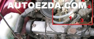
The following malfunctions may occur here: 1). Basically, the solenoid valve jet becomes clogged; 2). Winding failure; 3). There is no power to the solenoid valve (EMV).
To correct the operation of the idle speed sensor, you need to have wrenches 8, 10, 12, 13, 14, wires, a compressor, a twelve-volt light bulb.
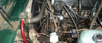
Algorithm for checking the idle speed sensor with your own hands: 1. It is necessary to remove the air filter cover, using a ten key, unscrew the air filter cover nut. 2. Next you need to remove the air filter itself. 3. Unscrew the 4. Nuts securing the lower part of the air filter with an eight-point wrench. 4. Remove the lower part of the air filter from the studs. 5. Start the car, remove the terminal on the solenoid valve and touch the solenoid valve contact repeatedly until you hear a clicking sound. 6. If there are clicks, you need to turn off the engine and use a thirteen key to unscrew the solenoid valve
Particular attention should be paid to the fuel nozzle: it is necessary to thoroughly blow out the fuel nozzle using a pump or compressor and put it in place. Reassemble all parts in reverse order. 7
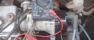
If there are no clicks, then turn the solenoid valve with a thirteen key. Using a special wire, connect the plus from the battery to the terminal of the EMC, the housing of which must touch the minus terminal of the battery. 8. If there are no clicks during this check, it means that the solenoid valve is not working properly. The idle speed sensor costs from 100 rubles
7. If there are no clicks, then turn the solenoid valve with a thirteen key. Using a special wire, connect the plus from the battery to the terminal of the EMC, the housing of which must touch the minus terminal of the battery. 8. If there are no clicks during this check, it means that the solenoid valve is not working properly. An idle speed sensor costs from 100 rubles.
But you can resort to old-fashioned methods! The idle speed sensor for the VAZ 2109 carburetor can be modified. For this purpose, it is necessary to break off the plastic tip of the EMC and install the nozzle in its place. Next, install all parts in reverse order.
9. If there are clicks, you need to put the idle speed sensor of the VAZ 2109 carburetor in place. Start the engine and use a tester to check if there is 12 volts on the EMC supply wire. If there is no power, then the electronic idle speed unit is faulty and needs to be replaced. Avtosotka
Location
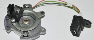
In VAZ 2109 cars with a carburetor, the Hall sensor is responsible for closing and opening the contact group. When the window screen rotates, a signal is sent to the device, which is converted into an electrical signal. Through the switch, the signal is transmitted to the ignition coil, where it is converted into an electrical discharge, that is, a spark.
In a car with a carburetor, the sensor is located on the ignition distributor under the dust cover. It is secured to the base plate with two screws or rivets, depending on the valve type.
Manifestation of malfunction and possible causes
Checking the ignition switch on a VAZ 2108, 2109, 21099 car.
Irregularities in the operation of the DH can be detected by the following indirect signs:
- There is a sharp increase in fuel consumption. This is due to the fact that the fuel-air mixture is injected more than once during one crankshaft rotation cycle.
- Manifestation of unstable engine operation. The car may begin to “twitch” and a sharp deceleration occurs. In some cases, it is not possible to reach a speed of more than 50-60 km/h. The engine stalls during operation.
- Sometimes the failure of the sensor can lead to the transmission being locked, without the ability to shift it (in some models of imported cars). To correct the situation, a restart of the engine is required. In case of regular such cases, one can confidently state that the DP has failed.
- Often, a breakdown can manifest itself in the form of the disappearance of the ignition spark, which, accordingly, will make it impossible to start the engine.
- The self-diagnosis system may experience regular failures, for example, the check engine light will come on when it is idling, and the light will go out when the speed increases.
It is not at all necessary that the listed factors are caused by the failure of the DP. There is a high probability that the malfunction is caused by other reasons, namely:
- ingress of debris or other foreign objects onto the DP housing;
- the signal wire has broken;
- water has entered the DP connector;
- the signal wire is shorted to ground or the on-board network;
- the shielding sheath on the entire harness or individual wires is torn;
- damage to the wires supplying power to the DC;
- the polarity of the voltage supplied to the sensor is reversed;
- problems with the high-voltage circuit of the ignition system;
- problems with the control unit;
- the gap between the DC and the magnetic conductive plate is incorrectly set;
- Perhaps the reason lies in the high amplitude of the end runout of the camshaft gear.
Design and principle of operation
The controller design consists of the following parts:
- magnet;
- rotor;
- chip;
- plastic housing;
- conclusions;
- magnetic circuits.
The sensor operates based on the Hall effect. The principle of operation of the element is as follows:
- The rotor has four teeth that rotate while the engine is running.
- Pulses are constantly read.
- The received information in the form of a signal is sent to the switch.
- The pulse arrives at the installed coil.
- An increased voltage of 22–25 kV is supplied to the spark plugs.
The type of functioning is not complicated.
How to check and replace the Hall sensor on a VAZ 2108 at home?
Common faults
Replacing the ignition switch on a VAZ 2108, VAZ 2109, VAZ 21099
Main device malfunctions:
- failure of the device itself;
- a break in its power supply wiring;
- poor contact with the on-board network.
The fact that the Hall sensor of the VAZ 2108 needs repair or replacement can be determined by the following symptoms:
- the car engine has become difficult to start when hot, in some cases it does not start at all;
- the power unit began to shake during operation, and jerking may be felt when driving at high speed;
- when driving at low speeds, engine power drops significantly;
- in some cases, the car owner may encounter the problem of increased fuel consumption.
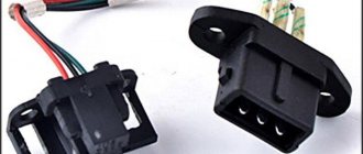
New Hall sensor for G8
Sensor diagnostics
There are several options for diagnosing the device:
- The simplest and most reliable method is to replace a failed regulator with a new one that is known to work. If after replacement the engine begins to work normally, then most likely the problem lies in the controller itself. It happens that the sensor is working properly, but its contacts are acidified or burnt; in this case, when dismantling the regulator, part of the oxide may fall off, so the driver may think that the problem lies in the device. Therefore, before diagnosing, it is necessary to clean the plug.
- Using a multimeter, you can measure the voltage at the output of the device. If the controller is in working condition, but the voltage should be from 0.4 to 11 W.
- Another test option is to make a circuit with a voltmeter. To do this, you will need to take a spark plug, one threaded end should be connected to the vehicle ground (body or engine), and the other should be connected to the coil wire. After this, remove the carriage and connect the plug. When the ignition is turned on, the tip of the screwdriver will need to be held close to the sensor. If at this moment you notice that a spark has jumped, then the regulator is working.
- Another diagnostic method is device imitation. To do this, you need to remove the plug with three connectors from the controller, then turn on the ignition and connect outputs 3 and 6. If at this moment a spark appears, this indicates a failure of the controller (the author of the video is the altevaa TV channel).
Replacement Guide
If diagnostics show that the device is faulty, you need to check the quality of its connection. If you are sure that the contacts are in good condition and the wiring is intact, then the VAZ Hall sensor is replaced. This operation can be performed at home, detailed instructions are given below. To replace, you only need pliers and two screwdrivers - one with a Phillips head and one with a flat head.
Stages
So, how to correctly change the device on your G8:
- To gain access directly to the controller, you need to dismantle the ignition distributor located in the engine compartment. After the distributor is removed, you also need to disconnect and dismantle the slider; to do this, pull it up and remove the protective cover.
- Next, using a flat-head screwdriver, you need to unscrew the screw that secures the regulator. Once the bolt is unscrewed, the connector can be removed from the ignition distributor cover.
- After completing these steps, you need to use the same screwdriver to unscrew the two screws that secure the regulator support plate.
- Having done this, you need to unscrew two more bolts that secure the vacuum corrector.
- The next step will be to dismantle the vacuum corrector. To do this, you need to remove the locking pin from the inside, and then disconnect the corrector rod.
- After all these steps are completed, you need to unbend the wire clamp and pull the controller support plate up. To replace the sensor, you only have to unscrew two more bolts that secure it. Installation and further assembly of the structure is carried out in the reverse order.
Video “How to change the Hall sensor on a Nine - visual instructions”
Visual instructions for replacing the device on the domestic “Nine” are shown in the video below; in the case of the “Eight”, the replacement procedure will be similar (the author of the video is the channel All from the life of “one person”).
Replacement
To make your own repairs, you need to be prepared. It is recommended to use a well-lit garage, and to dismantle the parts you will need a simple set of tools: a marker, a 10 mm wrench, a Phillips and flathead screwdriver. We will consider an example of replacing the hall sensor on a VAZ 2109 with dismantling the distributor. The step-by-step process is as follows:
- Secure the vehicle in gear or with the handbrake.
- Disconnect the negative terminal on the battery.
- Disconnect the high-voltage wires, marking with a marker which one was located.
- Remove the vacuum regulator hose.
- Disconnect the power supply from the hall sensor.
- Unscrew the top nut securing the distributor and wire bracket.
- Unscrew the bottom and rear mounting nuts.
- Use a marker to mark the location of the distributor so that you can install it back without unnecessary displacement and without adjusting the ignition timing.
- Move the distributor to the right along the studs.
- Take it to a well-lit workbench.
- Unscrew the screws of the ignition distributor cover and remove it.
- Remove the slider and plastic boot.
- Unscrew the plug screw.
- Remove the screws of the support plate.
- Remove the vacuum corrector (2 screws).
- Take out the block and wires.
- Remove the support plate with the sensor.
- Unscrew the two mounting screws on the DH and remove it.
- Install a new sensor.
- Collect everything in reverse chronology.
When disassembling the distributor, it is recommended to clean it of dirt using: injector cleaner, gasoline or acetone. It is most convenient to wash parts with a narrow paint brush. Inspect the ignition distributor cap very carefully. There should be no cracks on its body, and the contacts and ember should be in good condition.
Working principle of the Hall sensor
Malfunctions of the distributor of VAZ 2108, 2109, 21099 cars
A Hall sensor is a device that detects changes in the electromagnetic field. In fact, it is a switch that is triggered when a magnetic field appears near it, and the whole essence of its operation in a car is to obtain data on the position of the crankshaft and camshafts for the timely supply of the air-fuel mixture to the cylinder and its ignition. The consequence of failure of such a sensor is a complete stop of the engine, since the engine control system “does not know” what positions the pistons and valves are in, and this is fraught with serious consequences.
In Lada Vesta cars, the Hall principle is used in the phase sensor. It is located on the intake camshaft pulley. There is a slot in the pulley, which, when passing by the sensor, changes its potential to 0 volts and transmits this information to the engine control unit. At this moment, the piston of the first cylinder is at TDC on the compression stroke.
Purpose of DC in the car ignition system
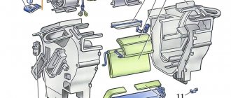
Having understood the principle of operation of the Hall element, let's consider how this sensor is used in the contactless ignition system of the VAZ line of cars. To do this, let's look at Figure 5.
Rice. 5. Principle of the SBZ device
Designations:
- A – sensor.
- B – magnet.
- C – plate made of magnetically conductive material (the number of protrusions corresponds to the number of cylinders).
The operating algorithm of such a scheme is as follows:
- When the chopper-distributor shaft rotates (moving synchronously with the crankshaft), one of the protrusions of the magnetically conductive plate takes a position between the sensor and the magnet.
- As a result of this action, the magnetic field strength changes, which causes the DC to operate. It sends an electrical impulse to the switch that controls the ignition coil.
- The voltage required to form a spark is generated in the Coil.
It would seem nothing complicated, but the spark must appear at a certain moment. If it forms earlier or later, it will cause a malfunction of the engine, even stopping it completely.
Appearance of the Hall sensor for SBZ VAZ 2110
Hall sensor, checked with a multimeter.
KEY-DOP
How to find a suitable video. about this situation here Support the project! MAP.
The switch passes voltage through the sensor and records its configuration when the roller rotates, which happens when you try to start the engine.
As for the rest, what remains for our client to do is exactly the same as with contact ignition, then a spark is supplied just when the slider is opposite the spark plug contact. If the Hall sensor in the distributor on a VAZ 2109 stops working, a spark will not be created as it should, and the engine will not be able to start.
The switch also takes on only the task of controlling the ignition angle; it does this automatically based on engine speed.
Connection diagram
The figure shows a basic electrical drawing for the VAZ 2108 and 2109 with pinout of contacts.
The ignition system operates as follows:
- The wire transmits voltage to the sensor from the switch through the red wire.
- A magnet creates a field.
- An impulse is supplied to the switch through the green wire.
Using a Hall element, the voltage directed to the high-voltage coil is regulated.
Self-check and replacement of the Hall sensor on a VAZ 2106
The Hall sensor is one of the main elements of the contactless ignition system of the VAZ 2106 engine. And this device, like all others in domestic cars, tends to break down periodically. Therefore, we will tell you how to understand that the Hall sensor of a VAZ 2106 is broken, how to check it and how to replace the device.
Tuned car VAZ 2106
Problems in the functioning of the Hall sensor on a VAZ 2106 car can manifest themselves in different ways. Sometimes even an experienced specialist will not be able to detect a breakdown. Therefore, we will look at the main symptoms that may indicate a malfunction of this element:
- the engine becomes difficult to start or does not start at all;
- the car does not work well at neutral speed: jerking may occur periodically, the car stalls;
- when the car picks up speed, the engine may twitch and stall;
- The engine occasionally stalls while driving.
If one of these symptoms is typical for your car, then this, of course, may indicate other malfunctions. However, first of all it is necessary to check the Hall sensor of the VAZ 2106.
How to check?
There are several methods that will help determine the functionality of the Hall sensor on your car. Let's look at these methods in more detail:
- The simplest method is to diagnose the operation of a VAZ 2106 engine with a new, known working Hall sensor. If you have one, install it in place of the old one and try to operate the car. If the problem has disappeared, then the answer is obvious.
- Try checking for spark in the engine. This is done when the ignition is turned on. To do this, it is necessary to dismantle the block installed on the distributor, which is called the distributor. Now turn on the ignition. After this, you will need to take a small piece of wire and connect its ends to the third and sixth outputs of the switch. If a spark appears while connecting the wire, this means that the Hall sensor of the VAZ 2106 has failed and needs to be replaced.
- You can also check the functionality using a voltmeter. You need to connect the device to the sensor output. If the Hall mechanism is working, then the voltmeter will respond to it. In this case, the device arrow will fluctuate from 0.4 V to 3 V.
New mechanism for VAZ 2106
Replacement process
So, if you encounter problems with the mechanism, you will need to replace it. It's not that difficult. What will you need for this?
Preparing the tools
Prepare in advance:
- wrench set to “13”;
- screwdriver;
- pliers;
- hammer.
Wrench 13 3. Long screwdriver Pliers Construction hammer for work
Phased replacement
- First, turn off the engine and open the hood of the car. The supply pipe must be disconnected from the vacuum corrector.
- After this, you should unclip the ignition distributor cap and remove it.
- You will then need to unplug the connector of the device you want to replace. Using a wrench set to “13”, you next need to unscrew the nut that secures the holder plate.
- Now remove the distributor.
- Using a hammer, knock out the clutch spring screw from the ignition distributor.
- Then, using a screwdriver, unscrew the screws that secure the vacuum corrector. The corrector needs to be pulled out. This gives you access to your engine's Hall sensor. Using the same screwdriver, unscrew the screws that secure it and remove the mechanism.
- Replace the device with a new one. All subsequent assembly should be done in reverse order. After replacement, take a test drive to ensure that the device is working properly.
B In general, the procedure is not particularly complicated, but, as in any other matter, there are some nuances
For example, you should knock out the clutch spring screw with force, but carefully. Deformation of parts will subsequently lead to worse results.
AvtoZam.com
Types and scope of application
Despite the variety of elements that use the Hall effect, they can be divided into two types:
- Analogue, using the principle of converting magnetic induction into voltage. That is, the polarity and voltage directly depend on the characteristics of the magnetic field. Currently, this type of devices is mainly used in measuring technology (for example, as current, vibration, rotation angle sensors).
Hall effect current sensors can measure both AC and DC current - Digital. Unlike the previous type, the sensor has only two stable positions, indicating the presence or absence of a magnetic field. That is, operation occurs when the intensity of the magnetic field has reached a certain value. It is this type of device that is used in automotive technology as a sensor for speed, phase, camshaft position, as well as crankshaft, etc.
Why is a Hall sensor needed and how does it work?
The device of the contactless ignition system of the VAZ 2107 car has such an element called a Hall sensor. Its fundamental purpose is the ability to detect the angle of the crankshaft and camshaft of the power unit. The Hall sensor is not installed on injection models of sevens, it is installed only on carburetor ones.
According to the value of this device, voltage pulses are supplied to the spark plugs. The functioning of this element is based on increasing the voltage in the cross-section of a wire placed in a magnetic field. The element is connected by three terminals, two of which provide power supply (plus and minus), and the third contact is intended directly for supplying a signal. The device received this name due to a special effect that was identified by scientist Hall. In the distributor on the shaft there is a plate that is part of the control of the device controller.
When the motor operates, the metal in the slots alternately changes, and the magnet, which is located inside the controller, begins to be excited by oscillations of the magnetic field. In this case, the controller generates voltage pulses issued by the switch and supplied to the coil. The coil, in turn, raises the voltage to a high value and transports it alternately through armored wires to the spark plugs
Knowing the operating features, you need to deal with the malfunctions, but before that it is important to note that the Hall sensor on the VAZ 2107 is located in the distributor under the cover. To replace it, you will need to disassemble the distributor
Basic sensor malfunctions
Any part on a car sooner or later begins to malfunction, and the Hall sensor is no exception, even though it has the simplest design. Its breakdown is detected by detecting the following defects:
- Inability to start the engine.
- Unstable and unstable operation of the motor.
- The occurrence of jerks.
- The engine begins to stall.
- The appearance of the detonation effect.
If the above symptoms appear, then there is no need to rush to change the Hall sensor, since similar phenomena can also occur due to other breakdowns of the ignition and fuel supply system. To verify that the device is faulty, you will need to perform a suitability test.
Check Features
The BSZ contactless ignition on the VAZ 2107 has a Hall sensor, the serviceability of which determines the normal operation of the internal combustion engine. If you suspect that it is faulty, then you need to check the Hall sensor. To do this, there are different ways on the basis of which one can draw a conclusion about the suitability of the element.
The following two methods are used to check an element:
- The simplest test method is to install a known-good element. If the signs of malfunctions immediately disappear, it means that the breakdown was detected correctly and successfully repaired. The disadvantage of this method is that you must first purchase a working element.
- Use a multimeter to check the voltage at the sensor output. The device switches on the voltage measurement mode, after which the value at the device output is measured. The value should be between 0.4 and 11 Volts, and if this is not the case, the element should be replaced.
- Simulation of device operation. The test diagram is as follows - the element terminal should be removed from the connector, and then turn on the ignition. Now we begin to simulate the operation of the Hall sensor, for which contacts 3 and 6 of the switch output are connected. If sparking occurs, the element must be replaced.
Description of the operating principle of the sensor
The G8 electronic ignition system consists of the following elements:
- The main distributor of the ignition system, in which a photoelectric sensor is installed that records the position of the camshaft (Hall sensor).
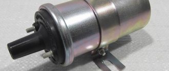
- High voltage coil.
- Electronic control unit - switch.
- High voltage wires.
The high voltage coil has two windings. The primary is connected to the circuit with the battery through a switch, relay and ignition switch, while the circuit is constantly closed. When the ignition moment is approaching in one of the cylinders and the piston is close to top dead center, the Hall sensor, mounted on the same axis with the camshaft, records this moment and signals it to the switch. It should be noted that in more modern schemes this function is performed by the crankshaft position sensor.
In modern circuits, the crankshaft position sensor functions as a hall sensor
The commutator, having received an impulse, breaks the circuit of the primary winding of the coil. In this case, a high voltage electromagnetic pulse is generated in the secondary winding, which has a much larger number of turns than the primary. It is supplied again to the ignition distributor through one high voltage wire, reaching the central contact of the slider. The latter transmits an impulse to one of the four cylinders, in which the fuel mixture needs to be ignited. After completing the cycle, the commutator restores the circuit of the primary winding of the coil and waits for the next signal from the Hall sensor.
As can be understood from the principle of operation of the circuit, the VAZ 2108 photoelectric Hall recorder is a key element of the circuit; without its normal operation, there will be no spark discharge on the spark plugs. Therefore, in the event of a car malfunction such as the disappearance of a spark, you need to immediately check the operation of two elements: the switch and the photoelectric sensor. In the first “eights” and “nines”, it was the switch that most often failed due to an imperfect design.
Since this problem was subsequently corrected, the main cause of ignition system failure is usually a malfunction of the recorder. The latter cannot be repaired, and in case of incorrect operation, the Hall sensor must be replaced.
Return to contents
Search on the site
This is the Hall generator.
Everything is very simple. The next step is to carefully unsolder the legs of the element from the test circuit and connect it to the standard connector contacts.
You turn on the ignition.
The sensor circuit includes a power supply that converts unipolar supply voltage into bipolar power supply to the circuit. Pull out the pin using pliers. In a working device, the voltage will vary from 0.4 V to 11 V. Thanks to simple techniques, the motorist will save his time on repairs, and also eliminate unnecessary waste of money.
The impulses arise due to the fact that the slots do not go through the same distance, but through different ones, that is, they alternate. Replacing the sensor: instructions for motorists To install a new ignition sensor, you need to correctly remove the one that has failed. Resistors R1, R2 set the output current of our pulse sensor.
Disconnect the distributor cover. The third wire is used to transmit a signal, the polarity of which changes relative to the common power wire. Connect a voltmeter to the sensor output. The use of such a sensor will require monitoring the speed of the output shafts of gearboxes, monitoring the direction of rotation of two or more synchronized mechanisms, and accounting for fluid flow.
Magnetic field sensors. Hall sensors in MK circuits
We check the work again with a tester and at this point the work on repairing the Hall sensor can be considered complete. If it is impossible to install a working sensor, you can use a simple device that will duplicate its operation. But the Hall generator is most widely used in the automotive industry - for measuring the position of camshafts and crankshafts, as a non-contact electronic ignition and for other purposes. The first devices turned out to be quite bulky and not very ergonomic.
The use of neodymium magnets, the strongest permanent magnets, allows you to fit a sufficient number of small-sized magnets on the disk. Typically, replacing a Hall sensor consists of several steps: First of all, the distributor is removed from the machine. Also, do not exclude other ignition system malfunctions found in cars. The new Hall sensor is installed in the reverse order. The easiest way is to replace the device with a working one. installation of ignition with a hall sensor on a motorcycle. BASHKIRIA STERLITAMAK
What is it needed for
The Hall sensor is used to determine the angular position of the engine crankshaft and camshaft. This device is found in cars such as AUDI, Volkswagen Golf and Passat, BMW, Suzuki, Opel, equipped with a contactless ignition system.
In an outdated contact ignition system, this element is used as a component of the distributor (ignition distributor).
That is, such a part is found in any modern car, including many models that have been proven over the years, for example, VAZ (“ 2108 ”, “2109”, “1111”) and GAZ-24-10. In accordance with the readings of this device, current is supplied to the spark plugs in the cylinders.
How to check the performance of the Hall sensor?
There are different ways to check the serviceability of the SBZ sensor; we will briefly talk about them:
- We simulate the presence of DH. This is the easiest way to quickly check. But its effectiveness can only be discussed if a spark does not form when there is power at the main components of the system. To test, follow these steps:
- disconnect the three-wire plug from the distributor;
- we start the ignition system and at the same time “short” the wire with ground and the signal from the sensor (pins 3 and 2, respectively). If there is a spark on the ignition coil, it can be stated that the SBZ sensor has lost its functionality and needs to be replaced.
https://www.youtube.com/video/sLaqztwsMEE
Please note that in order to detect sparking, the high-voltage wiring must be close to ground
- Using a multimeter to check. This is the most well-known method, and is given in the car manual. You need to connect the probes of the device, as shown in Figure 7, and measure the voltage.
Connection diagram of a multimeter for checking DXO; oscillogram of a working Hall sensor SBZ
- Installation of a known working HH. If there is another sensor of the same type available, or it is possible to borrow it for a while, then this option also has a place to exist, especially if the first two are difficult to do.
There is another verification option, which is similar in principle to the second method. It can be useful if you don't have measuring instruments at hand. For testing, you will need a 1.0 kOhm resistor, an LED, for example, from a lighter flashlight, and several wires. From this entire set we assemble the device in accordance with Figure 9.
Rice. 9. LED tester for checking DH
We carry out testing according to the following algorithm:
- Check the power supply to the sensor. For this purpose, we connect (observing polarity) our tester to terminals 1 and 3 of the DC. Turn on the ignition, if everything is normal with the power supply, the LED will light up, otherwise you will need to check the power circuit (after making sure that the LED is connected correctly).
- Let's check the sensor itself. To do this, we “transfer” the wire from the first terminal to the second (signal from the DC). After this, we begin to turn the camshaft (by hand or with a starter). The blinking of the LED will indicate the serviceability of the DC. Otherwise, just in case, we check that the polarity is correct when connecting the LED, and if it is done correctly, we replace the sensor with a new one.
To find out the condition of the sensor, you need to check the element. There are several ways to do this. Let's look at them:
- The simplest option is to install a known-good device, which you can borrow, for example, from a friend in the garage.
If the problem disappears during the check and the engine starts working without interruptions, you will have to go to the store to purchase a new sensor. A simple way to check the DC on a VAZ 2107 is to install a known-good element, which can be borrowed from a friend in the garage - Diagnostics with a multimeter. To do this, the device is set to the voltage measurement limit and measurements are taken at the sensor output. If it is working properly, then the multimeter readings should be in the range of 0.4–11 V.
- You can simulate a sensor.
The procedure is simple: remove the DH connector from the distributor, turn the key in the ignition switch to the “ignition” position and connect the 3rd and 6th terminals of the switch. You can use a series-connected LED and a 1 kOhm resistor, which are connected in the same way. When a spark appears, this will indicate that the device being tested has worked. One of the options for testing a Hall sensor is simulating the device
Which to choose
Manufacturer Number Cost in rub.
| LADA | 21080-3706800-00 | 590 |
| AVTOVAZ | 21080370680082 | 240 |
| GALLANT | GLSS133 | 230 |
| AUTO ELECTRONICS | 21080370680000 | 195 |
| AVTOVAZ | 21080370680001 | 190 |
| REMCOM | RK02008 | 150 |
Factory products may have different endings in numbers, for example, 1, 2, 3 and so on. It's not fake. This is simply a product produced at a related enterprise of the Tolyatti auto giant.
Signs of breakdown
If the DC fails, the car itself will notify you that there is a fault. To determine problems with the diesel engine, there are certain signs coming from the engine:
- You simply cannot start the engine;
- There are interruptions in the operation of the power unit - the smooth running becomes not so smooth, jerks appear;
- Idle speed is broken or completely absent;
- The engine may suddenly turn off or stall;
- Motor power is noticeably lost.
Before you run to the engine compartment and change the Hall sensor, first you need to make sure that it is the cause of all the troubles with the engine. Still, the signs are indirect, and they can be caused by a malfunction of other elements of your car.
Installation location
Checking status
There are several main methods that are used today to check the current state of the Hall sensor. Let's get to know each of them in more detail, and you decide for yourself which one you will use the next time you check the DH on your VAZ 2109.
Verification method
Your actions
Replacing an old device with a new one
This is the simplest method, which will require you to have a spare Hall sensor on hand, of which you are confident that it will work. Simply remove the old sensor, insert the new one in its place and try to start the car. If everything works, you have found the reason. If not, you will have to look for the source of the problems in other systems.
Checking the output voltage
For this method, you will need a tester connected to the output of the device. If the Hall sensor is working properly, the tester will show values in the range of 0.4-11 Volts. If the data does not meet the established standards, the household will have to be replaced
Simulation of device operation
A popular method in which you deceive your own car by simulating the operation of the Hall sensor. You need to remove the plug block, turn on the ignition and connect outputs 3 and 6 together. If a spark starts to jump, you can be sure that your sensor has failed.
Checking without additional devices
Here you don't need a tester or voltmeter. First, connect the lead from the coil to the spark plug, and connect the thread of the spark plug to ground. Remove the carriage with the sensor and attach the connector. Now you can turn on the ignition. Using a screwdriver, move the tool near the device - the Hall sensor. If a spark appears on the spark plug, this indicates the serviceability of the DH. If not, the conclusion is obvious.
Device check
If you discover that the DC is faulty, you should definitely replace the device. We do not recommend delaying this event.
There is nothing particularly difficult about replacing the DH on a domestic nine. Therefore, even a novice driver can take on the job with his own hands.
- Disconnect the negative terminal from the battery.
- Disconnect the armored wires from the distributor, disconnect the hose from the vacuum corrector.
- Next, remove the gas cable and put it aside for now so as not to interfere with the process.
- Unscrew the bracket fasteners that hold the wires. Remove the bracket from the stud and move it aside. Otherwise he will disturb you.
- Be sure to draw a straight line on the auxiliary drive housing and distributor. This location will allow you to avoid disturbing the ignition timing during reassembly.
- Disconnect the power supply with wires.
- Remove the plugs from the clutch housing and turn the flywheel with a screwdriver so as to set the piston of the first cylinder to the top dead center position.
- To remove the distributor, you need to unscrew two more mounting nuts holding the device.
- Remove the cover from the distributor, remove the slider and pull it up. Only a little.
- Remove the dust cover.
- Now unscrew the mounting bolt to remove the plug.
- We also need to unscrew the bolts that hold the plate of our desired sensor.
- Remove the vacuum corrector mounting bolts, remove the retaining rings, corrector and rod.
- To get the wires out, you will need to release the clamp there.
- Remove the mounting plate and unscrew the mounting bolts, which will allow you to finally remove the failed Hall sensor.
- It is now necessary to install a new sensor and assemble the unit, proceeding in the reverse order.
It is important not to change the ignition settings
Don’t forget, after completing the work, be sure to check whether your carburetor VAZ 2109 is working correctly, and whether you have violated the ignition timing.
The main difficulty in the process of replacing the diesel engine is the need to get to the sensor, as well as the existing risks of disrupting the proper operation of the carburetor. But if you act carefully and strictly according to the instructions, problems can be avoided.