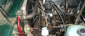
Recommendations for connecting high-voltage wires.
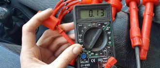
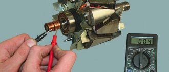
The first step is to check the high-voltage wires for resistance using a multimeter tester.
Resistance should not exceed 20 KoM. When you install the wires, do not be lazy to lay them out correctly, without kinks, so that they do not come into contact with other parts of the motor. This will increase their service life. Lay the wire correctly and secure it. The first cylinder in front-wheel drive cars VAZ 2108, VAZ 2109, VAZ 2110 is located closer to the timing belt. If you look at the engine from the front, the first cylinder is the leftmost). The cylinders are counted from left to right - 1, 2, 3, 4.
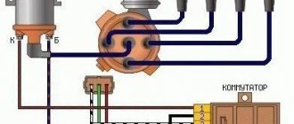
The procedure for connecting high-voltage wires on a VAZ 2108, VAZ 2109, VAZ 21099 with a carburetor engine
The central high-voltage wire comes out of the distributor cover and is directed to the ignition coil.
The outlet of the distributor cover , directed towards the front of the machine , is connected to the first cylinder.
The output of the distributor cover , directed downwards , is connected to the third cylinder.
The rearward outlet of the distributor cap is connected to the fourth cylinder.
The output of the distributor cover, directed upward , is connected to the second cylinder.
The high-voltage wires in the ignition system of the VAZ 2109 are designed to transmit an electric current pulse from the ignition distributor to the spark plug. A high-voltage wire has the following characteristics: 1. Resistance 2. Electrical voltage of transmitted pulses 3. Breakdown voltage
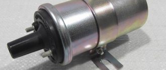
High-voltage wires VAZ 2109
1. The most important parameter that you should pay attention to when choosing high-voltage wires for a VAZ 2109 car is resistance . According to the technical data sheet of the VAZ 2109 car, the wire resistance should be 2.55 kOhm. I remember my surprise when, out of curiosity, I decided to measure the resistance of the wires on my nine and saw the numbers 7 - 8 kOhm on the multimeter screen. There is a simple logical explanation for this: the lower the resistance of the high-voltage wire, the higher the level of electromagnetic interference emitted by it. Modern cars are equipped with a large number of microprocessor and microelectronic devices, which are subject to regulated requirements for the level of electromagnetic compatibility. Therefore, for imported wires intended for modern injection foreign cars, the resistance of the high-voltage wire is 9 - 25 kOhm, this is a completely normal figure. It’s another matter when a VAZ 2109 made in 1991 has such wires. I’ll explain why: the greater the resistance of the high-voltage wire, the weaker the spark on the spark plug. Also, the higher the resistance, the later the ignition becomes. Therefore, a VAZ 2109 with a high-voltage wire resistance of more than 10 kOhm will have higher fuel consumption and will be much more difficult to start in winter. Of the electronics, the old VAZ 2109 only has a switch and an economizer, so they are not as demanding of electromagnetic interference as modern foreign cars with dozens of sensors, immobilizers, on-board computers and other electronics. Checking the resistance of an explosive wire is very simple: take a regular multimeter, set it to resistance measurement mode and measure the resistance of the wire.
How to check
A new or used hall sensor for VAZ 2108-2109 can be checked. The most common are 3 methods: connecting another DC, diagnostics with a multimeter and the simulation method.
- For the easiest method, you will need a new or used HH. Disconnect the power supply from the sensor on the distributor and connect it to a separate DC. Remove the center wire from the distributor cap and place it on ground so you can see the spark. Turn on the ignition. Use a knife or thin screwdriver to move from side to side inside the magnetic element, simulating the operation of the screen. If there is a spark, then the DC is working, and if not, then it is defective.
- For this method you will need a multimeter, which must be converted into a voltmeter. If you carry out diagnostics outside the car, you will need a power source. This could be a 6 V motorcycle battery, a 9 V Krona battery, or a laboratory device on which you can make a low voltage of 4–9 V so as not to spoil the DC. The sensor has 3 contacts at its output. They are arranged in the following sequence: + / 0 / − (plus, pulse and minus). We connect plus and minus from the power source. Take the negative probe of the multimeter and attach it to ground. Insert the positive probe of the tester. If you move inside the sensor from side to side with a screwdriver or a knife, simulating the operation of the screen, then the voltage on the tester display should change from 0.4 V to 11 V. If so, then the DC is working.
- There is another way to check the hall sensor on a VAZ 2109 (carburetor), but without a multimeter. The method is called imitation. Applicable in the absence of another household. The process looks like this: disconnect the power supply from the sensor. Then remove the center high voltage wire from the distributor and place it on the engine ground so you can see the spark. Next, you need to close pins “3” and “6” on the switch with a jumper and watch for the spark. If it slips, then the sensor is faulty, and if it is not there, then the problem is somewhere else (wires, switch, etc.).
Diagram, procedure for connecting VAZ high-voltage wires.
First, let's decide which of the four cylinders is first?
The first cylinder in front-wheel drive VAZs is located closer to the timing belt. If you look at the engine from the front, the first cylinder is the leftmost). And then everything is simple - from left to right - 1, 2, 3, 4.
In rear-wheel drive VAZ Classic and Niva, the first cylinder is located closer to the front bumper of the car.
General tips for connecting high-voltage wires.
Checking high-voltage wires. To check the wires, you will need a multimeter tester. Check the resistance of the wires - it should be no more than 20 KOhms (in practice, the longest wire of cylinder 1 has a resistance of up to 10 KOhms). If the wire resistance is more than 20 Kom, it must be replaced. Carefully inspect the wires for chafing on parts of the motor or other wires. In case of significant abrasion, replace the wire. In case of minor abrasion, it is possible to lay the wire so that it does not rub and fix it in this position.
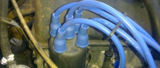
Laying wires. Do not try to connect the wires in a bundle. Disassemble the wiring harnesses, release the wires from the plastic holders. Connect the high-voltage leads to the corresponding cylinder spark plugs. Lay the wires so that they do not rub against each other, engine parts, or hoses. Avoid sharp bends and tension on the wires. After connecting all the wires, secure them into the bundle with special comb holders included in the delivery kit.
The procedure for connecting I/O wires to a VAZ carburetor (2108, 2109, 21099)
The central wire from the distributor cover always goes to the ignition coil (bobbin).
The outlet of the distributor cover, which faces towards the front of the car, is connected to the first cylinder.
The outlet of the distributor cap, looking down, is connected to the third cylinder.
The outlet of the distributor cap, looking rearward, is connected to the fourth cylinder.
The outlet of the distributor cap, looking up, is connected to the second cylinder.
The procedure for connecting high-voltage wires to a VAZ Classic, Niva with a carburetor and distributor.
Central wire from the ignition coil (bobbin)
1 cylinder - above the vacuum corrector. Next, clockwise, the order is 1-3-4-2.
Injection VAZ produced before 2004 with an old-style ignition module (4-pin low-voltage connector)
Actually, on the module body it is already indicated which cylinder the pins correspond to - but we duplicated them in red in case the module gets completely dirty, and you might not be able to see it in the photo.
resistance of high-voltage wires, high-voltage wires
High voltage wires with a copper core.
Automotive high voltage ignition wires carry high voltage from the ignition coil to the spark plugs. There are several types of high-voltage wires on sale. The simplest and cheapest ones consist of stranded wire with a thick layer of insulation. They are used for contact ignition. The resistance of high-voltage wires of these brands is almost zero, which ensures minimal high-voltage losses from the ignition coil. But low resistance and low breakdown voltage reduces the secondary voltage, since the self-induction voltage of the coil is reduced, which directly affects energy storage. Also, when using such wires, very strong radio interference occurs. The insulation of such wires also leaves much to be desired. As practice has shown, these wires practically do not work.
High voltage wires with carbon core.
The second type of wire consists of a central linen thread covered with ferroplast, on which iron-nickel wire is wound. The resistance of wires of this type is about 2 kOhm/m, which reduces radio interference. These wires are ideal for use on vehicles with a contact ignition system. Having relatively low resistance and low losses when transmitting high voltage. At the same time, radio interference is significantly reduced and the secondary voltage slightly increases. But the insulation of such wires also leaves much to be desired, especially with temperature changes.
Silicone high voltage wires.
Increased requirements for noise suppression of wires and an increase in secondary voltage have led to the creation of increased distribution resistance and increased insulation, capable of withstanding high voltages up to 40 kV. These wires are made of various materials and have silicone insulation. The resistance of such wires ranges from 5 kOhm/m to 15 kOhm/m. The insulation of such wires is very reliable and does not react to temperature changes and does not crack.
Checking high voltage wires
The high-voltage wires used in contact ignition are designed for a relatively low voltage of about 12 kV and have rigid insulation. This insulation breaks down, especially with temperature changes, resulting in voltage leakage to the housing. Determining this malfunction is quite simple. It is necessary to look under the hood with the engine running in the dark. The presence of sparking on the wires indicates a malfunction.
Connection features
The order of connecting high-voltage wires must be strictly sequential, since each cylinder of the engine corresponds to a specific socket on the ignition module. Considering that there is a numbering of the sockets on the ignition module body, the risk of confusing anything is minimal.
The procedure for connecting high-voltage wires of the VAZ 2114 injection type depends on the year of manufacture of your car. Fourteen cars before 2004 had 4-pin ignition modules installed, and cars after 2004 had 3-pin coils.
The connection diagram for VAZ 2114 high-voltage wires to the ignition module (until 2004) is as follows:
Connection diagram for VAZ-2114 with ignition coils (after 2004):
In the pictures you can see the numbers of the landing slots. Each number must have a corresponding cylinder connected to it (cylinder numbering is counted from left to right).
To correctly install high-voltage wires on the VAZ 2114, follow the following algorithm of actions:
- Turn off the ignition. Open the hood and remove the power terminals from the battery;
- We remove the old GDPs from the mounting sockets on the module and cylinders;
- We remember the location of the high-voltage wires of the VAZ 2114 and connect new GDPs according to the diagram. Before replacing, it would not be amiss to draw this very diagram by hand on paper so as not to confuse anything;
- We connect power to the battery and, to check whether we did everything correctly, start the engine.
When installing the wiring, do not try to connect individual air intakes to each other with plastic clamps; to do this, you must use the comb holder that comes with them. A thin clamp can easily wear through the insulating coating. Also make sure that the GDP does not bend.
Connecting armored wires on VAZ 2115 and 2113 is carried out in a similar way.
Armored wires for VAZ 21099 injector
In order to connect previously completely removed high-voltage wires in the correct order to the ignition module (coil) of the ignition system of the injection engine (2111) of VAZ 21083, 21093, 21099 vehicles, you need to know some features.
— On some types of high-voltage wires near the tips there are white rings with markings (or markings on the wires themselves). — On the ignition module, near each terminal there is a cast number of the cylinder to which it corresponds.
Often, due to contamination and inaccessibility, it is impossible to determine which numbers are printed on the ignition module. Using the diagram below: “Ignition module of the ignition system of engine 2111 of VAZ 21083, 21093, 21099”, it is enough to simply connect the high-voltage wires from each spark plug to a specific terminal of the ignition module.
Ignition module of the engine ignition system 2111 of VAZ 21083, 21093, 21099 cars, diagram, front view
numbered terminals of the ignition module for injection VAZ 21083, 21093, 21099
Notes and additions
— High-voltage wires running from the module to the spark plugs are of different lengths: the longest for the spark plug of the first cylinder, then in descending order.
— When replacing high-voltage wires, you should change them one at a time so as not to confuse the leads.
More articles on the ignition system of the injection engine of VAZ 21083, 21093, 21099 cars
Comparative test repair
How often should GDP be changed?
According to the recommendations of Avto-VAZ, replacement of high-voltage wires of the VAZ 2114 should be done every 30 thousand kilometers. In practice, motorists rarely comply with these replacement deadlines, since if the wires do not have any mechanical damage, they can travel about 100-150 thousand km.
When the service life is exceeded, the internal resistance of the GDP increases, which negatively affects the transmission of the electrical impulse. This leads to problems with ignition and acceleration dynamics, since when the supply of current to the spark plugs is delayed, the normal engine operating cycle is disrupted.
Features of the ignition module
Now let's talk about a more complex issue - the ignition module and its design features.
The design includes several components, each of which has its own nuances.
| Component | Peculiarities |
| Ignition coil | There are always two coils on a VAZ 2109. This mechanism is responsible for generating current |
| High voltage switches | Switch keys also work together. Through them, the current goes to the spark plugs, plus the controller regulates the time the current is turned on, which is calculated by receiving information from the crankshaft sensor |
| Electronic control unit | Responsible for distributing information in the form of electronic impulses |
| Frame | High-strength plastic is used for its manufacture, which largely ensures the durability and reliability of the device. |
Ignition coil
Location
Any work related to repair, testing, and maintenance of the ignition module will be impossible to perform if you do not know basic things - the location of the device.
You can find the ignition module (ignition module) in the engine compartment. Find the high voltage wires that go to the spark plugs. One end is connected to them, and the other goes to the module. The MZ is small in size and enclosed in a plastic housing.
Device location
Principle of operation
Initially, on carburetor cars, the system worked due to the presence of an ignition coil. With injectors everything is somewhat different.
- Initially, the ignition coil is turned on, generating a high voltage current. The coil operates on the principle of magnetic induction;
- Then the electronic control unit MZ is connected to the work, performing the functions of control, transmitting commands, and ensuring the flow of current required by the characteristics to the spark plugs;
- Next, the spark plugs activate the spark, ignition occurs, and so on.
Functionality check
To accurately determine whether it is time to change the high-voltage wires of the VAZ, you need to check their performance with a multimeter.
This operation will take you no more than 15 minutes:
- Turn off the ignition;
- We remove the wires: disconnect the first end from the ignition module, the second from the cylinder;
- We switch the tester to ohmmeter mode and connect the multimeter probes to the wire contacts.
If the high-voltage wires on the VAZ 2114 are in normal technical condition, the multimeter will show a resistance within the value indicated on the wire insulation; if the readings are different, the armored wires on the VAZ 2114 need to be replaced. The process must be repeated on each wire in turn.
If the test shows disappointing results, there is a possibility that the problem of increased resistance lies in oxidized contacts. In this case, you can try to revive the VVP by wiping the contacts with VD-40 or carburetor cleaning fluid.
Also, the cause of problems with ignition can be a breakdown of the GDP. You can determine it visually in the dark - take a flashlight and open the hood of the fourteenth, find and inspect the armored wires, if you notice a slight spark on the insulation - the air intakes are broken and need to be replaced.
Fresh questions for auto repair shops (replacement of high-voltage wires for vaz lada 2109) in Moscow
I want to change the dashboard on a VW KADDY 3 Restyle '10, can you help?
I want to write a review about this service. I am repairing my Zafira there, the most important thing is that there is no deception there, they don’t impose anything, they don’t scam me. Vice versa! Warn against unnecessary spending! About the quality, I can say something about what they did.
Good afternoon do you have a vibration stand?
Hello! I need to replace the rear brake pads on a Peugeot Partner Teepee. Is it possible to do this at your place and what is the price for such work? Thank you.
Kiel Blinton 05.12.2010 - 17:56
Good day everyone! Forgive me if the topic is button accordion, but there is no one else to ask. Question - I have an engine 2110 engineer, I bought high-voltage wires and foolishly removed the old ones, but I didn’t remember the connection sequence. If I am facing the car, then the numbering of the candles is 1 2 3 4? But how do they all connect to the square ignition module? If anyone knows, please explain or draw a diagram, please.
Attached images
Post edited by Kiel Blinton: 12/05/2010 - 18:03
Typical electrical wiring faults
Malfunctions, as a rule, boil down to the fact that electric current either does not flow to the spark plug at all, or if it does, it is in limited quantities. And this happens for the following reasons:
- When the current-carrying conductor through which the impulse passes breaks
- If there is a current leak, this means that the insulation is damaged, there is a breakdown of current on the side
- The resistance value exceeds the permissible value
- There are problems with the contacts (either with the spark plug, or with the distributor and ignition coil).
If a current-carrying wire breaks, then an internal spark occurs, in other words, a spark discharge is formed between the ends of the broken wire, which greatly reduces the voltage and also causes a parasitic electromagnetic pulse to occur. So:
- The resulting impulse, of course, negatively affects the correct operation of the vehicle’s electrical sensors
- Just one such defective high-voltage electrical wire often causes vibration and interruptions in the operation of the motor.
- In addition, a damaged high-voltage electrical wire leads to ignition in the cylinder with some delay or even every other time, then the synchronization of the operation of the cylinders and the engine as a whole is disrupted
Checking electrical wires
Anyone can check the wires, and do it with their own hands; this does not require electrical knowledge, or special hard-to-find tools or assistants, only the knowledge of what to do and in what order:
- First, you need to check the spark plug wires on the VAZ 21093 visually for visible damage (for example, cracks, kinks, etc.).
- Then you should make sure that there is no breakdown, this can be done even in the absence of any measuring instruments, it will be enough to look under the hood, with the engine running, when it gets dark, if there is a breakdown, then a spark will be visible while the engine is running on the broken electrical wire
- You can also check high-voltage electrical wires using a wire; you just need to take a piece of wire at night and strip the ends on both sides. Then you need to close one end of the wires to ground (this is the body of the machine), and take the other end with your hands and move along the entire length of each electrical wire, not missing joints and caps, etc. A spark will occur at the breakdown points
You can also measure the resistance of high-voltage electrical wires; for this we need a tester (multimeter):
- Turn on ohmmeter mode
- We remove the wire from the spark plug of the first cylinder, disconnect it from the distributor (see The device of the VAZ 2109 distributor: the difference between contact and non-contact ignition systems and adjusting the ignition timing)
- We connect the multimeter electrodes to both ends of the wire and check the readings
For serviceable electrical wires, the resistance varies from 3.5 to 10 kiloohms, it all depends on the type of electrical wires themselves. The resistance value is usually indicated on the insulation of armored electrical wires. When checking each wire, the spread between the values cannot exceed 2-4 kiloohms. If greater variation is detected, the wires should be replaced. By the way, the replacement is made as a set, that is, all together at once; the price here is not a reason to save money all together. In conclusion, we present to your attention the resistance readings for the most popular armored electrical wires:
- Tesla brands have a resistance of 6 kOhm
- Brands Slon (Elephant) with a range from 4 kiloOhm to 7 kiloOhm (where 4 kiloOhm goes to the 1st cylinder and so on up to 7 kiloOhm on the last cylinder)
- ProSport brands have almost zero resistance
- Brands Cargen (Kargen) with a resistance of 0.9 kiloOhm
Note: The resistance of armored electrical wires varies and largely depends on the thickness, length, and material used to make the wires.
Sereshka 05.12.2010 - 18:01
Kiel Blinton (05.12.2010 - 17:56):
Good day everyone! Forgive me if the topic is button accordion, but there is no one else to ask. Question - I have an engine 2110 engineer, I bought high-voltage wires and foolishly removed the old ones, but I didn’t remember the connection sequence. If I am facing the car, then the numbering of the spark plugs is 1 2 3 4. But how are they all connected to the square ignition module? If anyone knows, please explain or draw a diagram, please.
There should be numbers on the module itself.
What can be changed in the electrical circuit
Let's figure out what exactly car owners undergo alterations.
Moreover, we will indicate only those alterations that are not prohibited by the manufacturer and current regulations:
- Installation of a new instrument panel;
- Alteration of internal (interior) lighting;
- Installation of additional turn signal indicators in the rear view mirrors;
- Installation of additional headlights (fog lights);
- Installation of an acoustic and multimedia system;
- Immobilizer installation.
For reference: the visual differences between the standard panel and the “high” one are that the radio compartment is moved to the level of the dashboard. Accordingly, the wiring on the VAZ 2109 under the instrument panel must be replaced.
Interior modifications
Many owners come to mind with the desire to improve the lighting in the car interior.
Let us remind you that inside a passenger vehicle there are several places equipped with lighting sources:
- The salon itself (interior lighting);
- Glovebox;
- Cigarette lighter;
- Instrument panel (instrument cluster lamp and symbol lamp)
If you, as the owner, like a high panel in the cabin, then you cannot do without replacing the standard wiring. Because the:
- Control devices have a different location on the panel;
- The standard length of wires is not enough;
- Terminal blocks may also differ.
Accordingly, without replacing the electrical wires it will not be possible to use:
- instrumentation;
- on/off buttons for various devices.
As for making changes to the instrument panel lighting, today there are sets of special lamps on sale along with the wiring with which they are connected to the car’s electrical network.
You can install such kits yourself; it is only important to adhere to accuracy and safety rules.
Advice: carry out all electrical wiring replacements and connecting instrumentation only with the battery disconnected.