In this article we will tell you how to repair a starter yourself, using the example of repairing a BATE 426.3708 starter.
You will need: a socket head “13”, a wrench, a screwdriver, keys “10”, “8”.
Remove the starter from the vehicle.
Remove the nut from the lower contact bolt.
Remove the washer and disconnect the stator winding terminal tip.
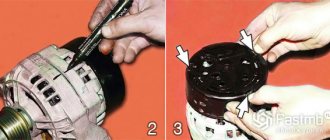
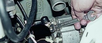
Remove the two screws securing the traction relay.
Remove the traction relay. To do this, disconnect the relay armature from the lever by lifting the relay.
Remove the armature and spring from the traction relay.
Remove the O-ring.
Using a tube of suitable diameter, knock the restrictive ring off the retaining ring.
NOTE
The restrictive ring is secured by a locking ring installed underneath it.
Remove the retaining ring and then the restrictor ring.
Unscrew the two fastening screws and remove the protective cover.
Remove the retaining ring...
Then the shims.
Unscrew the tie rod nuts
And remove the cover from the manifold side.
Use a screwdriver to press out the springs of both insulated brushes and remove the brushes from the brush holder.
Remove the brush holder
Features of the manual mechanism
In the selection process, most users usually prefer a manual starter. It has a huge number of advantages compared to electric and other options. Such a device includes the following parts:
- drum-shaped body;
- several springs;
- various fastening parts and cord.
It is the manual starter that is most popular, since during operation such devices often fail, so they have to be repaired, but manual options are extremely easy to repair. Let's look at what the process of restoring the starter's functionality looks like.
- Before starting repairs, you need to find a diagram from the manufacturer in order to understand the location of all the parts. In addition, it will be useful to understand the instructions.
- You need to prepare a wrench with which you can unscrew and remove the nuts.
- It's best to take a few photos before removing the starter. This will help you restore everything if you forget the location of certain parts.
- We unscrew the washer, which is located in the center of the drum.
- Find damaged elements and replace them.
Thus, repairing a recoil starter does not take too much time, which is why this type is very popular
In the process of restoring the functionality of a starter for a walk-behind tractor, the main thing is to pay attention to any details, even the smallest ones
NOTE
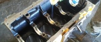
Four field windings are fixed in the starter housing.
Remove the plastic lever stop.
Remove the armature from the drive side cover.
Remove the intermediate support from the armature shaft.
Remove the retaining ring from the starter drive.
Preventing problems
Sooner or later, problems with the starter arise on any trimmer - Stihl FS 55, MTD 790 or another brand. It is possible to delay the occurrence of such a malfunction, but to do this you need to handle the tool carefully. In particular, you should not make too sharp jerks, as this will lead to the cord breaking or the spring flying out. It is not recommended to subject the lawn mower to impacts or other physical impacts. If the starter housing breaks and the cord breaks, it can become wrapped around the engine flywheel. This will lead to a torn pulley and a burst spring.
So, if you discover that the starter mechanism on your lawn mower is broken, you should not immediately rush to seek help from specialists. Knowing how to fix a malfunction and/or replace a part, you can perform repair work yourself. This does not require any specific tool. At first, the procedure may seem complicated and tedious, but numerous videos on the Internet dedicated to repairing the starter will help solve the problem as quickly and easily as possible.
NOTE
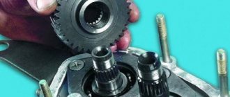
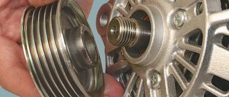
This is what the starter drive parts look like: 1 – gear; 2–drive lever; 3–overrunning clutch; 4-plate washer.
Remove the Belleville washer...
...thrust washer...
...clutch with lever..
...and a thrust ring.
Remove the two screws securing the traction relay cover.
NOTE
Disassemble the traction relay only when repairs are necessary.
Unscrew the nuts from the two contact bolts of the traction relay.
Using a soldering iron, disconnect both winding terminals from the traction relay terminals.
Remove the cover of the traction relay.
Remove the O-ring.
Remove the contact plate and rod assembly.
Remove the return spring from the rod...
...circlip...
...and an insulating washer.
Remove the contact plate...
Principle of operation
Many drivers know that their car has a starter, but do not know how it works and how it is designed. These drivers may wonder why the starter may not be working. Few people know, but there are two types of starter.
The first type of starter is a device with a gearbox. Almost all experts claim that this type of starter is the most practical and recommend using it. The fact is that this type helps the engine start even when the battery charge is low. This device also has a drawback, it lies in the fact that such a device is more susceptible to breakdowns, but most often this is due to the fact that there was a defect during manufacturing at the factory.
As already mentioned, there is also a second type of device, as you might guess, without a gearbox. This type has one advantage, which is its simplicity of design. This means that such a starter can be easily repaired.
The second advantage is that the ignition of the fuel mixture in the combustion chambers occurs due to the fact that the starting device is made without the use of a gearbox.
Thus, it turns out that if the first type ensures that the engine starts even when the battery charge is low, then the second type contributes to high torque.
The principle of operation of this device with a gearbox is based on the fact that electricity is supplied to the starter from the battery by turning on the ignition and closing the contacts, after which the engine starts. Before the engine starts, the armature converts electricity into the rotating action of the rotor using brushes.
NOTE
Contact plate mounting parts (shown in order of installation on rod).
...isolating sleeve...
...puck...
...and a damping spring.
Remove the contact bolts from the cover.
NOTE
The windings of the traction relay are installed in a non-separable housing, so if they are damaged, replace the traction relay assembly.
Clean all starter parts from dirt.
Check the condition of the stator winding. To do this, turn on the test lamp in the 220 V AC circuit and connect the wire to one of the terminals of the stator winding, and connect the other end of the circuit to the housing. If the lamp is on, it means the winding insulation is damaged. Replace winding or stator. Check the second winding in the same way.
List of tools required for repair
To repair a starter, approximately the same set is required, depending on the model and manufacturer of the unit. The table below provides an indicative list of tools that will be needed for repairs.
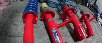
Table - Tools required to replace the front strut
| Name | Note |
| TORX head | Required mainly when repairing starters from foreign cars |
| Head | “at 8”, “at 10”, “at 12”, “at 13”, “at 14”, “at 15”. Size varies depending on the make and model of starter. |
| open-end wrench | For access where a socket or spanner cannot reach |
| Vorotok | With ratchet and extension |
| Multimeter | To check the electrical parameters of the starter |
| Cardan for wrench | Required if access to the starter or wire mounts is difficult |
| Screwdriver | With flat or cross blade. On foreign cars, a specially shaped tip is sometimes required, for example, flat with a notch or an “asterisk” |
| Insulating tape | To restore insulation |
| Penetrating lubricant | For loosening stuck threaded connections |
| Rags | For cleaning dirt and grease residues |
In order to repair a faulty starter, it is recommended to purchase a special repair kit. It includes the main elements of the assembly that are most susceptible to wear. Sometimes such a repair kit includes some of the tools necessary to restore the functionality of the unit.
HELPFUL ADVICE
The stator windings can be checked with a megger. Connect one contact to the terminal, the other to the stator housing. The winding resistance must be at least 10 kOhm. If it is less, replace the stator.
Inspect the anchor. If the collector is dirty or has marks or scratches on it, sand it with fine glass sandpaper. If the commutator is significantly rough or if mica protrudes between the plates, turn the commutator on a lathe and then sand it with fine glass sandpaper. The core runout relative to the shaft journals should not exceed 0.08 mm. If the runout is greater, replace the armature.
If there is yellow deposits from the bearing on the armature shaft, remove it with fine sandpaper, otherwise it will cause the gear to jam on the shaft. If nicks or nicks appear on the surfaces of the journals and shaft splines, replace the armature.
Check the reliability of soldering of the armature winding leads to the commutator plates. Inspect the winding at the ends of the armature: the diameter of the winding should be less than the armature iron package. If the diameter is larger, replace the armature
Check the condition of the armature winding using a test lamp in a 220 V AC circuit. Connect the wires to the commutator plate and the armature core. If the lamp lights up, it means there is a short circuit in the armature winding or commutator plate to ground. In this case, the anchor must be replaced.
Diagnostics
To check the functionality of the starter removed from the vehicle, use a charged battery. The ground is connected to the body. The positive wire is used to find a breakdown. If the plus is connected to the corresponding contact on the solenoid relay, it will work and extend the bendix, provided that it is working properly. If the relay does not work, then it is recommended to replace it or try to repair the starter yourself. Whether it’s a VAZ or a foreign car, it doesn’t matter - the unit is designed the same on all cars. But sometimes repair is impossible - modern relays are made non-separable. If the positive wire is connected to the contact after the relay, the starter should start. If nothing happens, you need to disassemble the assembly and look for a fault inside it.
HELPFUL ADVICE
The armature windings can be checked with a megger. Connect one of its contacts to the commutator, the other to the armature core. The winding resistance must be at least 10 kOhm. If there is less resistance, replace the armature.
While holding the overrunning clutch, try turning the starter gear in both directions: it should rotate freely only clockwise. If the gear rotates in both directions, replace the drive.
Place the starter drive onto the armature shaft. It should move freely, without jamming, along the shaft splines.
If drive parts are severely worn or damaged, replace the drive. If you find nicks on the leading part of the gear teeth, grind them with a fine-grained sanding wheel of small diameter.
Inspect the manifold side starter cover and intermediate support. If these parts appear cracked, replace them. Also inspect the bushings in the cover and support in which the armature shaft rotates. If severe wear or mechanical damage is detected, replace the cover or support with defective bushings.
Inspect the bushing pressed into the clutch housing. If the bushing is worn out or has burrs or holes, replace the bushing.
Symptoms
Often, malfunctions of the starting electric motor are disguised as damage to other vehicle components. In addition, repair of starters is complicated by the presence of both electrical and mechanical parts. Therefore, you need to “sin” against it last, when everything else has already been checked. This is especially true when you consider that the location where the starter is located cannot be called accessible. However, there are symptoms that first of all make you think about the performance of the electric motor. First of all, this:
- The starter solenoid relay clicks, but the armature does not rotate. In this case, the battery is obviously charged.
- The electric motor slowly turns the crankshaft. The engine will not start. Increased battery discharge.
- Rotation is accompanied by extraneous sounds (creaking, grinding, knocking, etc.).
If any of these faults occur, the starter will need to be repaired or replaced, but it must first be removed.
HELPFUL ADVICE
The bushing is located in a blind hole in the clutch housing and is therefore difficult to access. To remove the bushing, screw a tap of a suitable size into it until it touches the bottom of the hole, as if cutting a thread in the bushing. With further rotation of the tap, the sleeve will be pressed out of the hole.
Brushes worn to a height of less than 12 mm must be replaced
Check the movement of the brushes in the holders. The brushes should move easily, without jamming. Check that the brush holders are securely fastened: they must be securely fastened.
Insulated brush holders must not be shorted to ground. Check this with a test lamp.
Check the force of the springs pressing the brushes using a dynamometer. To do this, insert the armature into the cover on the drive side, install the housing and brush holder
Insert the brushes into the brush holders. At the moment the spring comes off the brush, the force should be in the range of 9.0–11.0 N (0.9–1.1 kgf).
Check the resistance of the traction relay windings with an ohmmeter. The resistance of the pull-in winding should be in the range of 0.52–0.59 Ohm (dashed red lines), and the holding winding – 0.725–0.795 Ohm (solid yellow lines) at an ambient temperature of +15 to +25 °C. The traction relay armature must move freely in the housing without jamming.
Main signs and causes of generator malfunction
1. Indication of the “battery” light on the dashboard or a message on the on-board computer. This indication occurs when the battery is not charging.
To monitor the charging process, use a multimeter. If the voltage on the battery while the engine is running is less than 12.6 Volts, the battery is not charging, you should look for the causes of the malfunction.
First, you should check the serviceability of fuses F4 and F6 along the generator power supply circuit.
2. The generator pulley does not rotate. The belt may break or slip. If the belt breaks, it must be replaced. If the belt slips, it is necessary to increase its tension.
3. Generator belt whistling. Such a malfunction may be the result of critical wear of the belt or the contact of various liquids on its surface.
It is necessary to tighten the belt, clean the working surface with a solvent, and replace it if necessary.
4. Changing the brightness of the external lighting (headlights) at different engine speeds. The cause of this symptom is usually a faulty voltage regulator or worn brushes.
How to check the generator for performance?
At the service station, the generator is placed on a special stand for testing. It measures the charge current and voltage at different generator speeds.
You can independently monitor a generator malfunction by measuring the voltage on the battery while the engine is running (should be more than 12.8 Volts). They also check the voltage at the main contact of the generator, where the voltage comes from the battery positive.
If it is missing, the cause may be a faulty generator fuse.
Typically in cars it is installed in the engine compartment fuse box. Its rating is more than 80 Amps.
Next, check the quality of the voltage regulator contacts and its performance. You can remove the voltage regulator without removing the generator. To test the regulator, two circuits are used.
Figure 5, 6
In the diagram shown in Figure 5, the light bulb should be lit, in Figure 6 - not lit. If the measurement results do not correspond to the required values, the voltage regulator should be changed.
A multimeter should be used to test rectifier diodes. If the diodes are broken (usually they are broken in pairs), they must be replaced. Assembled diode “horseshoes” are available for sale.
NOTE
At the same time as checking the winding resistance, check whether the contact plate closes the contact bolts of the traction relay. If the ohmmeter shows infinity, then either there is a break in the winding, or the plate does not close the contact bolts. In the first case, the traction relay must be replaced.
Inspect the contact bolts. Clean the burnt bolt heads with fine sandpaper. If the heads are severely burned out, you can rotate the bolts 180° so that they are pressed against the contact plate with the unburnt side. If the surface of the contact plate is heavily worn, it can be turned with the other side towards the contact bolts.
Cleaning contacts
Even modern generators and starters, designed for start-stop systems, are designed quite simply and have no fundamental differences from their ancestors
However, before taking tired components for repairs, it is important to make sure that the car’s electrical system is generally in good working order and that our heroes are not being terrorized by other enemies. Otherwise, you will soon have to pay decent money again for repairs or restoration
The death of a generator is very often associated with a substandard battery, which significantly increases the load on the unit. For this reason, the diode bridge and stator winding in the generator often burn out, and on some BMW models, even the stator itself. After such a disaster, the generator can be safely thrown into the trash.
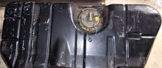
Also, the life of the generator drops noticeably if it ends up in an area of oil or antifreeze leakage. When the generator operates, the brushes naturally wear out and produce dust. And because of the oil that gets onto the generator, moistened dust particles return to the contact zone of the brushes and commutator - and, as they say, active abrasive wear occurs out of the blue.
In half of the cases, repairmen receive burnt starters, tortured by the car owners themselves. They turn the starter for too long (especially in winter) and overheat it in an attempt to start the engine, which may not start for a long time for a number of reasons.