If the arrow on the dashboard of the fuel level sensor of a Lada Priora remains motionless, regardless of the amount of gasoline filled, then it is necessary to urgently begin to look for problems that could cause this type of problem. All work can be done independently in a garage, and the only necessary tools you will need are a set of screwdrivers, pliers and a 10mm wrench.
Diagnostics and repair methods
To check and identify a malfunction, perform a number of preparatory work:
- Find a service hatch in the car that gives access to the electric fuel pump and float mechanism unit. Usually located under the rear sofa, where the fuel tank is installed.
- Unscrew the pressure flange and pull the assembly out through the hole. Clean all contacts and the rheostat plate, reinstall the unit.
- Prepare a “control” with a light bulb and a multimeter.
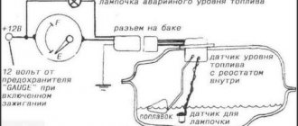
The first step is to accurately determine the “culprit” - check the sensor and pointer separately. The performance of the device is diagnosed as follows:
- Turn on the ignition and connect one terminal of the multimeter or test light to the ground of the car.
- Connect the second contact to the positive terminal of the wire going into the technological opening. The meter should show the voltage of the on-board network.
- Remove the positive terminal and short it to ground. If the instrument on the panel is working properly, the arrow will show a full tank. This means the fuel level sensor is not working.
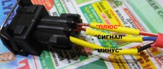
- If there are 2 wires coming to the gas tank, connect them alternately to the vehicle ground. From one the control lamp should light up, from the second the pointer should move to maximum. If the listed symptoms are observed, change the sensor.
In the case when there is a voltage of 12 volts on the wires, but after a short to ground the pointer indicator does not respond, you will have to disassemble the dashboard and remove the device. Similar actions are taken when the minimum gasoline remaining indicator is not working.
It is somewhat more difficult to independently check the updated system installed in cars of recent years; simply shorting the terminals will not do anything. Using a multimeter, make sure that there is supply voltage on the wires, and then you need to connect another, working sensor to them. If the arrow on the instrument panel reacts when the float moves, the element should be replaced.
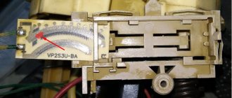
Thorough cleaning of the slider and rheostat turns helps in cases where the fuel level sensor simply lies. The moving contact can be carefully bent so that it passes along the unworn part of the turns. Clean the current-carrying strips of the potentiometer with a soft cloth soaked in alcohol to avoid damaging the surface of the element.
Some gasoline sensor malfunctions can be eliminated in a garage:
- a “sunken” float with a crack is replaced as an assembly with a lever or separately (depending on the make of the car);
- the torn conductors are connected using a conventional soldering iron;
- the damaged rheostat plate is replaced with a new one, provided that the spare part for your car is on sale.
At the moment, repairing the fuel level sensor is becoming irrelevant. Considering the cost of a new element, it is easier and more reliable to replace a non-working part.
If the indicator and the gas remaining meter are working properly, but the arrow of the device is lying, try making adjustments. Carefully bend the float rod in the desired direction and check the readings again. To achieve maximum accuracy, the operation will probably have to be repeated several times.
Many owners of VAZ cars have encountered the problem of unreliable reflection of information about the amount of remaining fuel. And, unfortunately, there may be several possible faults.
The wiring is faulty, the fuel level sensor has failed, or mechanical damage to the gas tank itself is the most common problem with this defect. If during the diagnostic process it turns out that the problem is in the sensor, it needs to be replaced.
Functionality check
There are usually many different and supposedly effective methods for testing with a tester or shorting a wire to ground. Alas, there is only one 100% correct way to check the FLS on a Priora. And this is done on the removed fuel pump module.
The description of removing this module is available in many articles and requires a lot of information. Therefore, we can only clarify that it is located under the rear seat of the Priores under a special hatch at the rear. Above the gas tank.
Therefore, the transition to an already deleted module.
Therefore, the procedure is as follows. Disconnect the chip with wires from the module connector. Turn on the ignition. Wait for the fuel pump relay to operate. Using a test lamp, check the current on the wire to the sensor.
Make sure the fuel level sensor float is in its lowest position. Connect the wires. Wait 5 seconds. The gas tank reserve light on the panel should light up. Slowly raise the float in the middle of its free stroke. The pointer arrow, accordingly, should show half the capacity. Raise the float all the way. As a result, the arrow will point to a full tank. This is with a working sensor.
If this does not happen, visually inspect the contact plate, clean it and try again. If there are no changes. You can switch devices.
Replacing the FLS
doing this on a remote module is very simple. The new assembly is sold complete with a harness of cables and connectors. You just need to disconnect the wires from the pump. Remove the chip from inside the module cover and, by clicking the two levers, remove the sensor plate on the wall. That's it, you can put on a new one. And check out his work as described above.
Video showing the device described in the topic:
Doesn't show fuel level AT ALL
When the arrow points to “0” with a full tank, then attention should be paid to all contacts and connections:
- First of all, this concerns the bolts located on the back side of the instrument panel, since they are the ones who create contact by fixing on the indicators.
- It is possible that the fuel level needle has lost its position and needs to be adjusted.
- The instrument panel itself may also be faulty. Since its mechanical parts are very susceptible to wear.
- We test all the “negative” wires, especially the one located near the handbrake. Because often it is he who is promoted.
- The float or the FLS itself is jammed.
Please note that if you have an on-board computer (not older models - approx.), it is possible to control the fuel level electronically. It is enough just to enter the readings, after each refueling of the car and the faulty FLS arrow will no longer bother you
What's the result?
Taking into account the above, it becomes clear that although the fuel level sensor is structurally simple, various breakdowns (both mechanical and electrical) can disable this element or cause malfunctions in its operation.
One way or another, the problem needs to be solved, otherwise the driver will have to constantly separately record data on how many kilometers have been traveled since the last refueling, how much more can be driven and when to refuel.
Finally, we note that often the best option is to replace the FLS with a new one; at the same time, it may also be necessary to change the fuel level sensor float. Less often it is possible to carry out repairs by removing oxides, moving to working sectors, etc.
At the same time, the most serious nuisance that leads to incorrect fuel level readings is considered to be a damaged gas tank. In order for the fuel sensor to work normally, in this case it is necessary to repair or replace the fuel tank.
Why is it necessary to clean the fuel pump mesh? When is it better to change and how to clean the fuel pump mesh? How to properly remove the fuel pump, subtleties and nuances.
What is the FLS fuel level sensor intended for: the design of the fuel sensor, types of fuel sensors and features, the operating principle of the FLS.
How to change a fuel pump. Location of the fuel pump, releasing pressure in the system, unscrewing the fuel lines, removing the pump, reassembling.
The causes of whistling and increased noise during operation of the fuel pump are overheating of the pump. How to diagnose and fix the problem yourself. Tips and tricks.
Why does the fuel pump grid need to be changed? How to remove the fuel pump yourself to replace the filter. Features of reassembly after replacing the fuel pump mesh.
How to determine why the fuel pump does not pump or works poorly. Fuel rail pressure, pump diagnostics. Wiring, relays, fuel pump fuses.
Purpose and location of the knock sensor
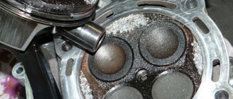
During explosive self-ignition in the combustion chamber of the fuel assembly, engine detonation appears. To monitor the occurrence of engine vibrations, a knock sensor (DS) is designed (video author – StarsAutoCom).
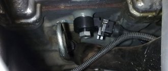
The DD is a plastic case, inside of which there is a sensitive piezoceramic disk element that generates an electrical impulse under mechanical influence from the resulting vibrations, and transmits information to the ECU controller. The detonation device is located on the front side of the cylinder block under the intake module.
Location of the device on Priora
If the check light comes on when starting on a cold engine
The “Check Engine” light on a Priora translated from English means checking the engine. However, on modern vehicles such as Mercedes and BMW, there is an automatic check of all systems and errors are displayed on the control panel screen, but on the Lada there is no such thing.
This icon lights up or blinks due to the following problems:
- some sensor, for example, oxygen, has failed;
- the light flashes when the spark plugs fail to operate;
- the injectors are clogged or the fuel pump is broken.
All these problems must be found and solved as quickly as possible so as not to lead to a major overhaul of the engine. Therefore, when a flashing light appears on the Priora check engine, you need to contact the service center and see experienced mechanics. Some will diagnose the problem and cure it.
In some cases, a small mobile device will help. It will help you see the problem in the garage, then you can look up the solution on the Internet.
Resetting the error on LADA Priora yourself (CHECK ENGINE)
Priora and
Priora temperature sensor, removing lambda probe 1 (oxygen sensor 1)./
Fuel level indicator for VAZ. Incorrect readings. repair.
Fuel level indicator and its malfunctions
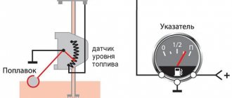
The measurement system in question operates using a rheostat with a resistor made from nichrome particles. The moving part of the rheostat, which is immersed in gasoline, moves under the influence of a lever with a float. The other side of the lever is an additional contact. If it is placed in a specific position, the circuit for regulating the process of replenishing reserve fuel is closed.
In this case, from 4 to 6.5 liters of fuel are allocated for reserve
Despite the importance of the device, on VAZ 2110 cars the fuel sensor quite often becomes faulty. But not all situations require mandatory replacement.
All you need is a small adjustment that will return the fuel level indicator to a working state.
If you notice a sharp change in the values of the fuel consumption indicator, most likely the contact track has become heavily worn under the influence of the slider. In case of minor wear, this can be corrected in a simple way. It is necessary to bend the slider mount so that it is located slightly above the problem area. Of course, if the contact track is significantly worn, it is better to replace it completely.
The next common pointer malfunction is incorrect readings, that is, the sensor indicates a value that does not correspond to reality. In this case, the device needs proper adjustment. In order to fix this problem, you need to disconnect the sensor from the VAZ 2110 gas tank, and then adjust the gasoline consumption indicator. The position of the arrow is adjusted manually; it must be moved from the stuck position to the original position, that is, to zero.
If the pointer is difficult to move and does not reach the desired position, you will need to bend the tab slightly to make adjustments, increasing the pointer's travel interval. It often happens that the fuel tank is more than half full, but the indicator indicates that it is completely empty. In such a situation, you will need to examine all pointer contacts for breaks or movement. The first thing you need to do is check the wiring under the dashboard.
There is a possibility that the fasteners holding the wires are loose and need to be tightened. If the instrument panel is fully operational, it is necessary to examine the intermediate paths for short circuits
It is important to check all the wiring, starting from the dashboard and ending with the connections of the ground wires and the handbrake handle. The absence of any results will indicate that the gasoline sensor needs to be replaced
Connecting the on-board computer of the VAZ tenth family
The route on-board computer (MBK or BC) has become an integral part of modern cars. I don’t think it’s worth talking about how useful it can be, but how to connect the on-board computer yourself is of interest to many. And also, is it possible to connect an additional on-board computer to the car? There are many trip computers for the “ten” (State, Gamma, Multitronics, Orion, Prestige, etc.), and as a rule, instructions for the on-board computer that describe the connection process are included. But it’s not uncommon for us to receive a used bookmaker, without the documentation we need. Installing an on-board computer with your own hands is not difficult, because the necessary block for connecting the BC is already inside the dashboard. It is a 9-pin trapezoidal block. The best way to get to it is through the right window of the dashboard. The pinout of the standard on-board computer connector is shown in the figure. Additional 10 and 11 contacts are not used on all BCs and are intended for connecting an external air temperature sensor. After we insert the block into the trip computer, all that remains is to connect the K-line. Why is K-Line needed? It is through this wiring from the ECU that the most significant information for us is transmitted (error codes, internal combustion engine temperature, etc.). The K-line is located in the diagnostic block (which is used at service stations to diagnose a car) to the left of the steering wheel, not far from the gas pedal. Our task is to connect the K-line to the on-board computer, that is, lay a separate wire from the BC block to this diagnostic block. Thus, the on-board computer will receive the information it needs and the diagnostic block will remain operational. The diagnostic block of the VAZ 2110, depending on the year of manufacture of the car, can be of two types: Euro-2 (GM) or Euro-3 (ODB-II). Where to find the K-line in the block is shown in the diagrams:
Second on-board computer in the car
It is possible to install an additional trip computer. A good example would be BC Sigma or State X1, which are installed instead of a small plug next to the SAUO block.
|
Thus, in our car there will be two on-board computers, one performs modest basic functions, and the second for diagnosing and setting ECU parameters. Digital errors on the on-board computer are easy to decipher.
Conclusion
It’s not difficult to install a bookmaker yourself; it’s much more difficult to decide on the choice of its model. We have already discussed where to buy and which on-board computer is better to choose in a separate article. In some models, it is also possible to install an external temperature sensor. By the way, on-board computers on the VAZ of the tenth family are available for old and new panels, but if you wish, you can install the BC for the new panel in the old one. xn--2111-43da1a8c.xn--p1ai
Removing and disassembling the fuel module
We are carrying out work to replace the fuel level indicator sensor, fuel pressure regulator, strainer and fuel pump. Relieve the pressure in the power system (see “Replacing the fuel filter”). Disconnect the wire terminal from the negative terminal of the battery. Inside the car, lift the rear seat cushion (see “Removing the rear seat”) and bend the sound insulation valve that closes the hatch cover in the floor of the body under the rear seat.
Use a Phillips screwdriver to unscrew the two screws securing the hatch cover...
...and remove the cover. Lifting the wire harness block clamp...
...disconnect the block from the fuel module cover connector.
By pressing the spring clamp, disconnect the tip 1 of the tee from the fitting of the fuel module cover. By squeezing the clamps (in the direction of the arrows) of tip 2 of the fuel supply tube, disconnect the tip from the fitting of the fuel module cover.
Using a 10mm socket with an extension, unscrew the 8 nuts securing the pressure plate of the fuel module. Remove the spring washers and the ground wire from the tank neck studs.
Remove the pressure plate.
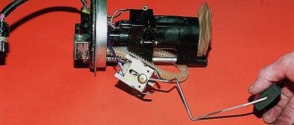
Carefully, trying not to damage the fuel level indicator sensor float, remove the fuel module from the tank. We drain the remaining fuel in the module into a previously prepared container.
If replacement is necessary, remove the ring plastic spacer.
Please note: when installing the spacer later, its cut must coincide with the protrusion on the fuel module cover
Remove the rubber sealing gasket. We close the hole in the fuel tank to prevent foreign objects from getting into it. We disassemble the fuel module on a workbench. If it is necessary to replace the o-rings of the fuel pressure regulator or the regulator itself...
...disconnect the tip of the ground wire from the terminal on the regulator body.
Using a screwdriver, remove the fuel pressure regulator mounting bracket.
Using pliers, remove the regulator from the module cover socket.
Remove the two rubber sealing rings of the regulator. Install the fuel pressure regulator in reverse order. We replace the regulator O-rings with new ones. Before installing the regulator O-rings, apply a thin layer of engine oil to the O-rings. To replace the fuel gauge sensor or fuel pump, the fuel pressure regulator does not need to be removed. From the inside of the module cover...
...use a screwdriver to press out the fixing plate of the common wire block...
...and disconnect the wire block from the cover connector. By pressing the latch...
...disconnect the wire block from the fuel pump. To remove the fuel level sensor...
...we release the two sensor latches...
...and move the sensor along the grooves of the housing towards the cover.
Remove the fuel level indicator sensor with wire blocks. Install the fuel level indicator sensor in the reverse order. When replacing the fuel pump, it is better to remove the fuel level sensor to avoid damaging it.
Use a screwdriver to pry up the drain tube... ...and disconnect it from the module body.
There is a retaining ring located in the groove of one of the guide posts of the module cover. We remove it by prying it with the blade of a slotted screwdriver.
By pressing the four latches of the pump holder...
...remove the fuel module cover assembly with the holder and the fuel pump.
Remove the spring from the guide post of the cover.
...remove the strainer.
Remove the lock washer from the slot in the strainer housing.
Using a screwdriver, press out the plastic latch of the holder...
...and use your finger to push the fuel pump out of the holder. We heat the plastic corrugated tube on the pump nozzle over a container of boiling water...
...and remove the tube from the pump connection. The car is equipped with a BOSCH fuel pump 0580454035.
A valve is installed in the fuel module housing to prevent fuel from leaking out of the housing. Assembling and installing the fuel module is carried out in the reverse order
When installing the strainer, pay attention to the condition of the lock washer; if it is dented, it must be straightened or replaced. When installing the fuel module into the tank...
...arrow 1 on the fuel module cover should be directed backwards (towards the trunk). Arrows 2 on the fittings of the fuel module cover indicate the direction of fuel movement. We put the tips of the tee and the fuel pipe onto the fittings of the module cover until the latches click. Before closing the hatch cover in the floor of the body under the rear seat, it is necessary to check the tightness of the fuel module connections. To do this, connect the wire terminal to the “negative” terminal of the battery and turn on the ignition.
Adjusting the readings
If the arrow periodically increases and decreases the values, then adjustment will help in this case.
Adjusting the fuel sensor (FLS) - removing the fuel pump
- Raise the rear sofa.
- We remove the fuel pump and clean everything from dirt. (More information about removing the fuel pump here).
Preparing to remove the fuel pump
If in any position the arrow indicates incorrect values, then it is necessary to bend the adjusting tongues on this side so that the float rod can move to the right or left freely, depending on its location.
The fuel gauge on the Priora shows incorrectly
The VDO instrument panel does not work. Temperature and fuel levels are “buggy”
Incorrect temperature and fuel readings? Probably many owners of VAZ 2110 - 2115 have already encountered the problem of incorrect display of fuel and temperature indicator on the dashboards of VDO, “Schetmash” Kursk, “Avtopribor” Vladimir.
The actual engine temperature is 90 degrees (we know this for sure), but on the instrument panel it shows 110 degrees. There are 10 liters of gasoline in the tank, but the instrument panel shows either 20 liters, then 15 liters, and sometimes correctly 10 liters. Moreover, usually the tachometer and speed always show the correct values. I had this problem for about a whole year. When I test the instrument panel (Press the daily mileage button - hold it down, turn on the ignition, all instrument indicator arrows deviate over the entire scale span and the LCD segments are completely filled, and the emergency fuel level warning lamp lights up. When testing the instrument panel, the temperature indicator should smoothly go a distance from 50 degrees to 130 degrees. The fuel level should smoothly go a distance from 0 to 1). If the pointers work correctly during the test, then the problem is electronics. Car service centers say that these instrument panels cannot be repaired. Just buy a new one of the same instrument panel and everything will be fine. It was a pity to spend money on a new VDO instrument panel (about 2,400 rubles), since the engine speed and speed of the car were shown, the temperature was monitored on the STATE 510 trip computer, and when refueling I had to set the gasoline in the same way on the standard computer. It was read theoretically from the controller. By the way, the calculation was quite accurate, but it was annoying to constantly put out gasoline.
By the way, here is another main feature that confused me, the fact is that the temperature gauge began to jump strongly when the car’s lights, low beam, etc. were turned on.
Recently I decided to tackle this problem and fully understand it. I didn’t really believe that it was an electronics failure. The solution turned out to be very simple. In fact, it was just necessary to bring a good “ground” to the instrument panel. Or just restore the default one. After all the tightening of the “ground”, the instrument panel began to work correctly. The temperature and fuel gauges now work accurately, even with the lights, heaters, etc. on.
All the “grounds” that need to be checked are described below: A fragment of the article was taken from the website www.chiptuner.ru
The first ground connection of the vehicle is located inside the instrument panel, on the top left of the relay and fuse mounting block, under the sound insulation. On cars of the first years of production, the ground wires to the welded stud were approached on top of the sound insulation, and then someone’s bright mind came up with the idea of hiding the wires under it. So access to the stud is very inconvenient and is only possible using a tube wrench or an extended 10-mm socket. If there is insufficient connection in this place, when you turn on the headlights or electric window motors, the windshield wiper and washer may turn on, and the central door locking system may work.
The second connection is located on a welded stud, on the center console of the instrument panel, on the left side, above the left console screen, under the M6 nut.
But even if this nut is tightened properly, and the problem remains, then we move on to the most important point of mass for the entire instrument panel, grounding the entire metal frame of the panel. This is a welded stud with M6 thread. It is located on the lower, inner (cabin) side of the engine shield, in the middle. The nut screwed onto this stud also secures the bracket that secures the front part of the left screen of the console, which some diagnosticians and electricians mercilessly remove due to the fact that there are frequent cases of damage to the ECM harness or central locking system on this bracket. As a rule, the nut is tightened very, very mediocre. If there is insufficient contact in this and the previous connection, when turning on the side lights, headlights and radiator fan motor, deviations of the temperature and fuel level indicator arrows are possible.
Car: VAZ-2112. Asks: Petrov Viktor. The essence of the issue: It incorrectly shows the fuel level in the gas tank or does not show anything at all, it sits at zero.
Source
Common problems
The system for monitoring the amount of fuel in the gas tank is subject to the following malfunctions:
- the indicator arrow is zero regardless of the amount of fuel remaining in the tank;
- the device does not display the fuel level correctly: it is located at the top or bottom;
- the arrow “jumps” or changes readings in a short period of time;
- The yellow minimum fuel indicator indicator does not light up.
Link. In some domestic car models, the fuel level indicator is still factory. An example is the Chevrolet Niva SUV of early releases, where the device greatly underestimates the actual fuel level. The driver, following the sign, went to a gas station, but found the tank full to the top.
The needle drops to zero for several reasons:
- A lever that gets stuck or jammed.
- The float lost its seal and sank to the bottom.
- Open circuit due to oxidized contacts or wiring problem.
- Failure of the indicator itself or the lever sensor - potentiometer.
Typically, erroneous readings and “jumps” of the needle are the result of contamination of the rheostat and cursor. On a car with high mileage, these parts can wear out - a thin layer on the plates wears out, causing contact between them and the runner to disappear.
The fuel level sensor in the tank sends conflicting signals that are reflected on the dashboard.
One of the reasons for the minimum level indicator not working is a burnt out light bulb on the instrument panel. Less common are problems with the final contact located inside the tank or broken electrical wiring. In newer systems, the lamp is also turned on by a command from the controller when the resistance of the potentiometer lever reaches a certain value.
Priora dashboard test
order in accordance with pressing the button: 1. Tidy test 2. Software version (1.1 IMHO) 3. Errors (the number 14 was displayed) 4. Deleting errors. Can you tell me more about this procedure? Which panel?
Can you tell me more about this procedure? Which panel?
if these are errors, then not the ECU, but the combination itself
This is what is written in the “Murzilka”: 1. The ignition is turned off. Battery included. 2. Press the “Reset” control button and, holding it pressed, turn on the ignition. All positions of the familiar areas (segments) should light up on the LCD—LCD control. 3. Press any of the control buttons. The LCD should display the program version (Ver 1.0). 4. Press any of the control buttons. The following error codes (if any) should be displayed on the positions of the first and second lines of the LCD: 2-overvoltage of the on-board network; 3-fuel level sensor error (if a break in the sensor circuit is detected within 20s); 4-error of the coolant temperature sensor (if an open circuit of the sensor is detected within 20s); 5-outside temperature sensor error (if there are no sensor readings within 20s, indication on the LCD is “-C”); 6-engine overheating (the criterion for triggering the acoustic alarm has been met); 7-emergency oil pressure (the criterion for triggering the acoustic alarm is met); 8-defect of the brake system (the criterion for triggering the acoustic alarm is met); The 9-battery is discharged (the criterion for triggering the acoustic alarm is met); E-determination of an error in a data packet stored in EEPROM. 5. Press the “Reset” control button and hold it for no more than 3 seconds. (maybe a typo, I need more than 3c). Error codes should clear to zero. 6. Press any of the control buttons. All positions of the familiar areas (segments) should light up on the LCD—LCD control.
From yourself if you do not press any control buttons for about 15-30 seconds. the panel enters the operating state.
“Reset” is the one that resets the daily mileage
PS I copied it somewhere from the forum
Where does this information come from?
Well, then tell me what the combination errors are. 7 If it's not difficult of course
(the criterion for triggering the acoustic alarm is met);
Tell me how to read fault codes through a check in a Priora? The “Change engine” light came on and there was nothing to look for. The terminal was removed, but the light still came on. No changes in engine performance were noticed.
We did this: Click on the daily mileage on the dashboard and turn on the ignition. The tidy starts to go crazy, and the display shows the following: (First display reading) UEr 2.1 (Second display reading shows the following) -23456 789E
Tell me how to read fault codes through a check in a Priora?
This is what is written in the “Murzilka”: 1. The ignition is turned off. Battery included. 2. Press the “Reset” control button and, holding it pressed, turn on the ignition. All positions of the familiar areas (segments) should light up on the LCD—LCD control. 3. Press any of the control buttons. The LCD should display the program version (Ver 1.0). 4. Press any of the control buttons. The following error codes (if any) should be displayed on the positions of the first and second lines of the LCD: 2-overvoltage of the on-board network; 3-fuel level sensor error (if a break in the sensor circuit is detected within 20s); 4-error of the coolant temperature sensor (if an open circuit of the sensor is detected within 20s); 5-outside temperature sensor error (if there are no sensor readings within 20s, indication on the LCD is “-C”); 6-engine overheating (the criterion for triggering the acoustic alarm has been met); 7-emergency oil pressure (the criterion for triggering the acoustic alarm is met); 8-defect of the brake system (the criterion for triggering the acoustic alarm is met); The 9-battery is discharged (the criterion for triggering the acoustic alarm is met); E-determination of an error in a data packet stored in EEPROM. 5. Press the “Reset” control button and hold it for no more than 3 seconds. (maybe a typo, I need more than 3c). Error codes should clear to zero. 6. Press any of the control buttons. All positions of the familiar areas (segments) should light up on the LCD—LCD control.
Lada Priora hatchback 2008, engine Gasoline 1.6 liter., 98 hp, Front drive, Manual - DIY
Comments 1
After replacing the sensor with a new one, it was still glitchy for the first 3 days (it hung in the lower position and did not float up), then it got used to it and it became just great.
We pay for photo reports on car repairs. Earnings from 10,000 rubles/month. Write:
Replacing the fuel level sensor itself on a Lada Priora is not that difficult, although to do this you will first need to remove the fuel pump. However, this is a small obstacle to not changing the sensor yourself. Replacing the fuel level sensor on a Priora is in many ways similar to a similar procedure on Kalina and Grant (1.6 engine), only the sensor mounting is slightly different.
Replacement process
Before you start replacing the Lada Priora FLS, it is recommended to leave a minimum amount of gasoline in the tank. Then the car is placed on a level surface, and the work is performed in the following sequence:
- Recline the rear seat.
- Open the hatch that blocks access to the sensor.
- Disconnect the wires from the contacts.
- Clean the part of the gas tank where the FLS mount is located from dirt and dust.
- Loosen the clamps and remove the hose.
- Unscrew the 8 bolts with a “10” key.
- Remove the sensor from the gas tank.
Installation of a new sensor is carried out in the reverse order of removal. When performing installation work, care must be taken not to damage the float or bend the lever to which this element is attached. The bolts securing the part should be tightened evenly, taking care not to strip the threads.
After installation and connection, the operation of the FLS should be checked. To do this, fill approximately half the tank with gasoline and drive on a bumpy road at slow speed. If the sensor readings approximately correspond to the fuel level, and the arrow on the dashboard does not deviate when driving on an uneven surface, then replacing the sensor can be considered successful.
How to prevent the problem
It is almost impossible to prevent sensor damage, since mechanical wear of the sectors or float is an absolutely natural phenomenon. Therefore, if the indicator needle begins to behave strangely, and the check reveals problems with the sensor, it is better to replace it as an assembly, fortunately its price is not very high.
The same statement is true if the indicator itself breaks down. Service work to prevent damage to this device is not provided - only replacement if a malfunction is detected. Problems with electrical wiring, including a break in the wire leading from the fuel level sensor to the indicator, can also be solved by replacing the wire.
Source
Suspension
Shock absorbers, Shock absorber strut, Shock absorber bump stop, Shock absorber boot, Shock absorber bushing, Rear shock absorbers, Shock absorber support, Support bearing, Front shock absorbers, Shock absorber silent block, Springs, Rear springs, Spring support, Front springs, Suspension arms, Control arm silent block, Rear control arm, Bolt Arm, Upper Arm, Left Arm, Lower Arm, Front Arm, Cross Arm, Right Arm, Trailing Arm, Ball Joint, Hub, Hub Bearing, Hub Nut, Hub Bolt, Rear Hub, Hub Cap, Front Hub, Hub Seal, Stud hubs, Stabilizer, Stabilizer bushings, Stabilizer links, Springs, Spring bolt, Spring bushing, Rear spring, Spring bracket, Spring leaf, Spring pin, Front spring, Spring cushion, Spring silent block, Spring shank, Spring stepladder, Air suspension, Air suspension compressor, Air springs, Air suspension unit, Steering knuckle, Swivel bearing, Trunnion, Kingpin, Rear beam, Beam silent block, Subframe, Subframe silent block, Wheel spacers