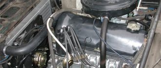
Replacing the timing chain and camshaft sprockets (carburetor engine)
Camshaft drive diagram
1 – limit pin; 2 – chain; 3 – tensioner shoe; 4 – chain tensioner;
5 – camshaft sprocket; 6 – chain damper; 7 – oil pump drive shaft sprocket; 8 – crankshaft sprocket.
| Remove the cylinder head cover (see here). Turn the crankshaft clockwise until the mark on the camshaft sprocket matches the mark on the camshaft bearing housing (see here). Remove the carburetor engine fan casing (see here). Remove the coolant pump drive belt (see here). Remove the crankshaft pulley (see here). Unlock and unscrew the bolt securing the camshaft sprocket, loosening the chain tension, remove the sprocket with the chain (see here). Remove the chain from the camshaft sprocket. We unscrew the three bolts securing the oil pan to the camshaft drive cover (see here). For clarity, we show the chain removal operations on a dismantled engine. Using a 10mm wrench, unscrew the three nuts and six bolts securing the camshaft drive cover to the cylinder block. |
Remove the camshaft drive cover. |
Using a 17mm wrench, unscrew the bolt securing the tensioner shoe. |
Using a chisel, bend the edge of the lock washer on the oil pump drive sprocket bolt.
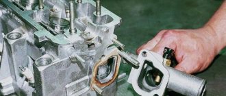
Using a 17mm wrench, unscrew the bolt securing the oil pump drive sprocket. |
Remove the bolt and washers. |
Using a 10mm wrench, unscrew the chain limiting pin and remove it. |
We take out the camshaft drive chain. We remove the sprocket from the toe of the crankshaft in the same way as on an injection engine (see here).
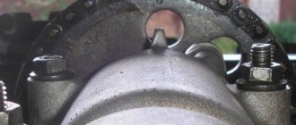
Before installing the chain, align the mark on the crankshaft sprocket with the mark on the cylinder block.
. and the mark on the camshaft sprocket with the mark on the bearing housing.
Install the camshaft drive parts in reverse order.
Having installed the chain, we tighten it (see here).
By turning the crankshaft clockwise two turns, we check that the alignment marks match.
We adjust the ignition timing.
Video
Source
Selecting tools and spare parts for replacement
Replacing the timing chain on a Chevy Niva is impossible without an inspection hole or a lift . Therefore, before you decide to carry out such repairs yourself, you need to find a suitable place. Convenient access from below is necessary to remove the engine protection and conveniently unscrew the auxiliary pulleys. You will have to remove the radiator with fans and drain the coolant. On average, the entire replacement operation will take from 3 to 5 hours.
Necessary tools for repair:
With spare parts for repairs everything is also simple . Buy them only from trusted stores and well-known brands. The abundance of spare parts for VAZ engines in stores does not always mean a quality product. Timing units from factory manufacturers and official conveyor suppliers have proven themselves to be the best.
Important! Parts for different VAZ engines may differ in design. The Chevrolet Niva has the VAZ 21214 engine model, while the classic Niva may have the VAZ 2106, 21213, 21214, 21218 engine and their modifications.
We will need:
Advice. It is convenient to combine such a labor-intensive operation of replacing the chain with other work on the engine. For example, replacing the pump, radiator, leaking oil seal, drive belts of mounted units and other minor repairs.
Timing marks VAZ 21213 carburetor
There is a standard 21213 NIVA, the engine of which has tractor traction at the bottom and lacks traction at speeds above 3000. Replacing the chain, all the sprockets, the camshaft with the bed did not solve the problem. Rearranging the chain on a tooth back and forth, too. It was noticed that the mark on the camshaft sprocket is not installed strictly opposite the protrusion; it can be placed half a tooth forward or backward. It was decided to check the valve timing. A device for adjusting valves with an indicator is welcome, but not at all required. However, I have it. The valve clearances must be properly adjusted!
When replacing the lower sprocket, check that the marks on the small sprocket and the pulley match. They correspond to TDC.
For example, we got 15 degrees.
By simple calculations (in our head) we find the valve overlap point (15 + 12.5)/2 = 13.75 degrees. This point, located at TDC, is considered optimal. In our example, the overlap point moved 1.5 degrees after TDC. You can check the pie chart of the valve timing and compare the result:
On my car, the mark, with new sprockets and chain, turned out to be shifted forward by 5 (!) degrees. This is where the tractor came from. Perhaps VAZ specifically places this mark with an offset in order to increase the torque at the bottom, or maybe during assembly they use sprockets from Lada cars. In NIV, the block is slightly higher, which is why the mark shifts. Don't know. To correct the situation, a split (adjustable) sprocket was purchased and installed:
With its help, you can smoothly adjust the position of the camshaft relative to the crankshaft + – 1 tooth.
If we set it so that the overlap point does not reach TDC, we get earlier opening of the intake, an increase in power at high speeds and a drop in traction at low speeds, and vice versa, the overlap point after TDC - we have tractor traction at low speeds, and stupidity at high speeds. Exact recommendations like “how many degrees to turn?” no one will give it to you. It all depends on the condition of the engine and personal feelings. However, you should not go more than half a tooth away from the point of zero overlap. It must be remembered that at large angles the pistons may collide with the valves. I made it so that the overlap point was shifted by 2.5 degrees before TDC, I got a good pick-up after 3000 rpm, and at low speeds the thrust remained almost unchanged. After all the manipulations, it is necessary to re-set the ignition timing, and it may be necessary to adjust the idle speed.
Good day! Since the engine won’t start and I have nothing else to blame, I decided to check the timing belt and valve marks, although the “master” who bored and assembled the engine for me swore that he assembled everything correctly. In general, I began disassembling, removed the valve cover, cranked the crankshaft, and yet it turned out that that same “master” had somehow placed a mark on the camshaft not at TDC, but at BDC. Now it became clear to me why the car wouldn’t start) Well, then I’ll tell you everything as a manual...
And so what we need for this whole procedure: 1. Special. a wrench for cranking the crankshaft (personally, I didn’t have one, so I just turned it with a 24 wrench)
2. Keys for 10, 13 and 17 3. Crowbar 4. Screwdriver 5. Feeler gauge 0.15 for adjusting valves (and it is better to take a special wide one, rather than a set of narrow ones)
First, remove the valve cover by unscrewing all the nuts by 10.
Then we rotate the crankshaft to TDC so that the mark on the pulley coincides with the long mark on the block.
When combining these two marks, the mark on the sprocket should also coincide with the ebb on the camshaft bed (if the mark is at the bottom, then rotate the crankshaft 360*)
If the marks do not match, as was the case for me, do the following: 1. Turn the crankshaft so much that the marks on the sprocket and the ebb match. 2. On the left side of the block, first leave the tensioner with a 13 key, and then unscrew the 2 nuts with a 10 and pull out the tensioner itself.
3. Unscrew the bolt securing the sprocket to the camshaft with a 17mm wrench (the main thing is not to drop the bolt into the engine)
4.Remove the star and, holding the chain with your hand, remove the star from the chain. 5.Holding the chain with your hand, we begin to rotate the crankshaft until the mark on the pulley and the long mark on the block coincide. 6.Then we insert the sprocket into the chain and install the chain tensioner in place, tightening only the nuts by 10. 7. From the inside of the chain, we begin to press the crowbar through the chain onto the shoe (the shoe in the photo below is what the tensioner rests on), so that tension the chain and at the same time try to put the sprocket on the shaft.
8.After putting on the star, screw it on and tighten the tensioner with a 13 key.
This completes the procedure for setting timing marks.
Now, without turning the crankshaft, leaving all marks in the matching position, we begin to adjust the valves. First, we adjust valves 6 and 8 (the valves are counted from the radiator) Then, having adjusted them, we turn the crankshaft 180* and adjust 4 and 7. Then, turning the crankshaft another 180* (in total, 360*), we adjust 1 and 3. Then we turn it another 180* (in general, already 540 *) and adjust 2 and 5.
The adjustment is made as follows: Loosen the lower nut with a 17 wrench, then insert the feeler gauge and turn the upper nut with a 13 wrench to adjust the gap (tighten it, increase it, unscrew it, decrease it). The probe should not go through tightly, but with very little resistance.
Having adjusted the valves, return the crankshaft and camshaft to the position where all marks coincide (4th cylinder at TDC) and now set the ignition. In this position of the crankshaft and camshaft, the slider on the distributor should point exactly to wire 4 on the distributor cap, or to the spark plug of the first cylinder. If this is not the case for you, then unscrew the nut 13 at the base of the distributor, lift it and turn it to the desired position. Then we put everything back together in reverse order.
All! This completes the procedure for all adjustments. Next, we start the engine and set the angle of the KSZ either by ear or with a control. Since I have BSDS, I did not do this.
Thanks everyone for reading. I hope this information helps someone. Good luck to you!
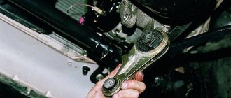
The main reason for replacing a double row timing chain is excessive stretching. The critical elongation is detected remotely by noise - the chain rattles and rubs against adjacent parts. In fact, extreme wear leads to loss of power, throttle response and unstable engine operation due to the mutual displacement of the camshaft and crankshaft. This will be visually indicated by a displaced auxiliary drive pulley.
What are tags and their purpose in the Shnivy mechanism
Marks in the timing system on a Chevrolet Niva car are special types of notches and holes that are located on the gas distributor pulleys. The photo shows pulleys with marks along which the timing chain is aligned.
See:
Aligning the chain with marks is done so that it is better fixed and holds the gas distribution mechanism itself. If you install the chain without following the marks, then the operation of the pulleys will be uncoordinated and will then lead to their rapid wear. Therefore, it is important, whenever replacing a chain or parts of a gas distribution mechanism, to install them in accordance with the marks. There may be a malfunction of the timing system when the chain tension is loosened or it is stretched. In order to correctly set the timing mechanism according to special marks, we will look at the procedure for installing the gas distributor phases on the VAZ-2123.
Setting the timing of the gas distribution mechanism using special marks
So, setting the phases in the timing system according to special marks on a Chevrolet Niva car includes the following sequence of actions:
Timing marks VAZ(LADA) 21214 NIVA
Installing timing marks
for VAZ(LADA) 21214
NIVA
. Sorry about the quality. The camera died.
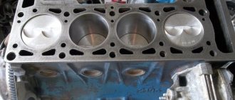
Part 2. Valve piston = repair Niva Chevrolet NIVA Chevrolet 44
Overhaul of the Chevrolet NIVA engine.
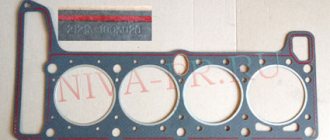
After repair work, it is recommended to replace the cover gasket.
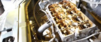
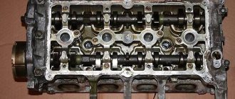
After the cover was removed, the following view is observed, shown in the photo below.
Under the valve cover
See:
Important! When unscrewing the bolt, it is necessary to control its position, because it is not fixed by anything and can freely fall into the engine sump. It is recommended that when loosening the tightening, unscrew it by hand or with a deep-head wrench.
When assembling, do not forget to replace the gasket on the cover!
The work carried out does not require much time, but is the key to the successful operation of the parts of the gas distribution mechanism of the Niva Chevrolet car. Drawing a conclusion, I would like to note the importance of setting the timing chain according to special marks. If for some reason you forgot to align the pulleys with the marks, then it is better not to start this process and make the adjustment again. This will extend the life of the timing system and all its components.
Do you still think that diagnosing a car is difficult?
If you are reading these lines, it means you are interested in doing something yourself in the car and really saving money , because you already know that:
And of course you are tired of throwing money down the drain, and driving around the service station all the time is out of the question, then you need a simple CAR SCANNER ELM327, which connects to any car and through a regular smartphone you will always find the problem, turn off CHECK and save a lot of money.
We ourselves tested this scanner on different machines and it showed excellent results, now we recommend it to EVERYONE! To prevent you from falling for a Chinese counterfeit, we publish here a link to the official website of Autoscanner.
Source
Adjustment or how to set timing marks on a VAZ 2106 yourself
Decoding notes
Without pre-basing the pistons and valves, installing the timing chain on the VAZ 2106 according to the marks is impossible. Therefore, the significance of the marks is not at all conditionally decorative. The signs give an understanding of the position of parts inside the motor:
For your information. The numbering of the “pots” starts from the radiator side.
How to restore tag matches
When the chain is pulled out, the marks will go away. The main difficulty is to return them to a position of mutual coincidence. This work is combined with dismantling the old chain. However, there is no need to rush to remove it - misalignment of all factory markers is fraught with danger.
The base is the position of the crankshaft at which the pulley mark coincides with the long line on the front cover. In this case, the drilling hole for the camshaft star should be closer to the high tide. This must be achieved first. It is worth remembering that the transmission is made with a 2:1 ratio - two revolutions of the crankshaft correspond to one revolution of the camshaft.
Unnecessary fears when dismantling the RV sprocket are not appropriate. The shaft design includes a pin. In addition to transmitting torque, it serves as a fixator of a certain position.
How to put on a chain
Installation of a new chain begins with its attachment to a new crankshaft sprocket. Next, the damper, tensioner shoe, and limiter are mounted. The chain is passed through the drive shaft gear and secured along the way. Afterwards it is mounted on the camshaft sprocket, and its position is adjusted according to the cycle:
The final procedure is to tighten the chain, during which the tensioner is twisted all the way with good force. After rotating the HF key, the final check of the coincidence of the signs is carried out.
Consequences of untimely replacement
Often the cause of repairs is an imperfect design of the hydraulic tensioner. To avoid this, many people replace the Chevrolet Niva chain tensioner from hydraulic to mechanical. Otherwise, operating the timing chain longer than expected can lead to disruption of the normal operation of the engine , and in advanced cases, to its overhaul.
The increased functional life of the components and simple replacement allow you to regularly replace the timing mechanism yourself. In combination with high-quality oil, this will significantly extend the life of the engine, and will save the car owner money and nerves.
Nuances in installing a timing chain according to factory marks on a VAZ 2106: pitfalls
It is difficult to achieve perfect alignment of two pairs of marks. The main reason is the use of components with dimensions within the maximum limit. By the way, adjusting the VAZ 2106 carburetor with your own hands also never follows the ideal scenario - additional recommendations from experienced craftsmen are almost always used.
Allowable elevation shifts
One of the unwritten norms allows for a discrepancy between the sprocket drilling and the camshaft bearing housing boss within a half-tooth in one direction or another. To be more specific, the installation of the timing chain of the VAZ 2106 engine according to the marks is considered complete when the camshaft sprocket is aligned exactly, and the mark of the crankshaft pulley goes slightly forward. This guarantees stable traction throughout the entire speed range.
If the camshaft star is aligned with the mark, and the knee pulley does not reach the TDC mark, the engine operates stably only up to a speed of 100 km/h. After crossing the border, there is a loss of traction and increased fuel consumption.
Extremes
A discrepancy of one tooth between the timing marks and the camshaft sprocket is unacceptable. This is usually evidence of critical chain stretch. When it is new, it is worth inspecting the seat under the key on the crankshaft - perhaps it is broken, hence the excessive play.
Engines with significant mileage are often prone to arbitrary changes in the location of the RV star mark during the rotation of the HF. This leads to:
For your information. Using a split star helps achieve perfect mark placement. It is installed to replace the standard camshaft gear.
Briefly about the main thing
The technology for setting timing marks on a VAZ 2106 engine is performed with the chain removed. A sprocket mounted on the camshaft without a chain is fixed with a screwdriver and tightened with a wrench. After rotating the camshaft in the desired direction and combining the drilling with the boss on the bed, the gear is again immobilized with a suitable object and dismantled. Next, the new chain is installed.
Perfect alignment of the marks can only be achieved by using a split gear. However, this is not at all necessary to comply with. It is quite possible that the camshaft marks coincide and the crankshaft pulley moves a little forward.
Source
Cause and investigation
We received a lot of questions by email: why was the double-row adjustable gear removed from sale, why don’t you offer a good double-row timing kit? The reason is simple: I don’t see the point. The double-row timing chain and the rubber coating on the tensioner shoe “ate” all the fine adjustments. Since I don’t like criticism and loudmouthing, without offering an alternative, I picked up and tested a single-row kit for a carburetor engine. Now you can put a good split gear on it, a tuning camshaft, and you will really feel the nuances when adjusting.
Replacing the timing chain Niva 21213 carburetor
Performance criterion. Possible consequences of wear
During the operation of the car, especially when the mileage has reached 100 thousand km or more, the chain is “stretched”. This term is not entirely correct. It lengthens not due to deformation (stretching) of the cheeks, but due to an increase in the pitch between the links due to wear of the hinge joints.
How to evaluate the suitability of a chain?
In practice, it is recommended to control chain elongation by the presence or absence of the possibility of its tension. You can also check the phases. If the mark of the camshaft sprocket coincides with the mark of the camshaft bearing housing, and the mark on the crankshaft pulley is located below the mark on the front engine cover by 10 millimeters or more, it is advisable to replace the chain. If the bushings are chipped or cracks appear on the “cheeks” (emergency condition), an immediate replacement of the chain is required.
What negative consequences does increasing chain pitch lead to?
To protect the engine from the described consequences, and yourself from unforeseen expenses, it is recommended to adjust the chain tension more often and more carefully.
Correct chain and link counting
Currently, there are many different chains on sale, including fakes from “gray” manufacturers, made no one knows where or how. How to distinguish the original chain from the “left” one? This seems quite difficult to do. But you need to remember that the bushings and chain links are hardened. You can check this by having a needle file with you. If you find “raw” metal, return the chain back to the seller.
| Or they can slip in a used chain. The figure shows the method that is usually used in practice. The chain is held flat with your hand. If the deflection is 7.10mm, then the chain is new, if the deflection is 17.20mm, then it has already worked hard. |
Among the original chains, we can recommend the Baltic, Czech, German - Sachs.
So, you decide to replace the chain and go to the market or store to get it. Know that there are two types of chains, for engines 2101, 21011 and 2103, 2106. They differ in different lengths. The chain of engines 2101 and 21011 has 114 links, and 2103 and 2106 - 116. The engine 21213 has a chain 2103-1006040. How can you quickly distinguish them from each other? Don't count the links! The method is very simple: stretch the chain and look at the outermost links on the left and right:
If they are the same, i.e. both extreme links are located inside or outside, then the chain has 116 links (Fig. b and c), if different, then 114 (Fig. a).
To replace the chain you need:
We assemble everything in reverse order.
It is better to schedule the work of replacing the chain during scheduled maintenance, in order to change the oil and filters afterwards.
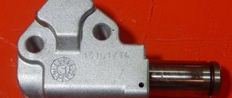
Chain tensioner and damper. Replacement
In the 21213 engine, two types of chain tensioners are installed: 21213-1006060 and 2101-1006060. Tensioner 21213-1006060 has a longer plunger. Recently, this tensioner has not been installed; At the factory, a tensioner 2101 is installed instead. The tension from it to the chain is transmitted through the shoe 21213-1006090. Dampener - 21213-1006100 - dampens vibrations in a long branch of the circuit.
When the engine is running, the entire timing drive mechanism wears out. Therefore, it is advisable to schedule the work of replacing all the sprockets, tensioner, shoe, stabilizer and front crankshaft oil seal to coincide with the scheduled replacement of the chain. Then, before putting everything back together, you need to:
The chain tension order is as follows:
How to get the debris
During the process of disassembling the engine to replace the chain, oil seals or if the damper breaks, as well as during careless movement, a bolt, washer, cracker, etc. can be dropped into the engine sump.
How to get bolts, crackers, fallen parts and/or their fragments? You don't have to remove the pan to do this. It is enough to remove the fan casing and its impeller, loosen the alternator belt, remove the crankshaft pulley and the front engine cover. This will give you access to the sump at the front of the engine. The only thing that will bother you is the oil that is in the pan. After this, you can feel the fallen object with your hand and easily pull it out. This method is less labor intensive than removing the pallet.
How not to change a chain
I'll tell you in a few words about this method. Only the engine valve cover is removed. One of the joints of the old and new chain is separated. The end of the new chain is attached to the right end of the old chain and pulled through the sprockets. Then both ends of the new chain are connected and the connecting pin is riveted.
I would call the link below “How not to change a chain”:
Many repair books describe how to properly replace a chain. Loosen the alternator belt, set all the marks correctly, block the crankshaft, unscrew the nuts and bolts of the front engine cover……. etc. So, I personally recommend changing the chain correctly in order to avoid unpleasant consequences and not have to pay twice and exorbitantly for engine repairs afterwards.
Update from Rask, 08/13/07.
When replacing the timing drive, pay attention to the axial play of the intermediate shaft. This may cause increased noise.
Chain 21214, operation
This is the most important part in the revised article. Operators and mechanics have a slang expression about the operation of mechanisms and engines - “in operating or normal mode.” Let me explain with a comparison, like the son of a doctor. A person has blood pressure and pulse, which are considered normal. Let it be 120/80 and 60-70 beats per minute. And suddenly there was a pounding in my temples, my pulse quickened - hello high blood pressure. In both the first and second cases, you will walk, think, eat. But in the first case, your body and heart in particular are working “in working mode,” and in the second, the situation needs to be corrected. The doctor has a tonometer and a stethoscope in his hands, and the control unit has a knock sensor that listens to the noise level in the engine. In fact, its purpose is to measure detonation in the cylinders, but if there are still extraneous loud sounds in the engine, then it will add them to the overall picture. In professional diagnostic programs, it is possible to look at the data before entering the ADC (analog-to-digital converter). For this circuit, the knock sensor readings are lower than on Ditton, from 3% and higher. The service life of this chain is also higher than that of the Baltic one; operation “in operating mode” is more than 100 thousand km. Just install chain 21214, not on factory stamped sprockets, but on turned sprockets, with teeth made on a gear-cutting machine, otherwise there will be no fun. It is for this reason that I do not recommend purchasing a chain separately. Or at least with a set of sprockets, or better yet a complete timing belt set.
Replacing the timing chain and camshaft sprockets (carburetor engine)
Using a 10mm wrench, unscrew the three nuts and six bolts securing the camshaft drive cover to the cylinder block.
Remove the camshaft drive cover.
Using a 17mm wrench, unscrew the bolt securing the tensioner shoe.
Using a chisel, bend the edge of the lock washer on the oil pump drive sprocket bolt.
Using a 17mm wrench, unscrew the bolt securing the oil pump drive sprocket.
Remove the bolt and washers.
Using a 10mm wrench, unscrew the chain limiting pin and remove it.
Before installing the chain, align the mark on the crankshaft sprocket with the mark on the cylinder block.
Step-by-step instructions for replacing the timing belt yourself
Repairs begin by preparing the car for partial engine disassembly . To do this, the machine is placed on a pit or a lift. Remove the engine protection, drain the antifreeze from the radiator, dismantle the main radiator with cooling fans. Loosen the fastening of the power steering pump and generator, remove the drive belts.
With an air conditioner, there are 2 options : drain the refrigerant and dismantle the radiator, or carefully move it to the side and hang it so as not to break the hoses. We disconnect all the cooling system hoses that interfere with the repair area. Remove the air filter, throttle cable, air pipe. In this semi-disassembled form, you can proceed directly to replacing the timing chain.
VAZ 21213 | Removing the chain and sprockets of the camshaft drive of a carburetor engine
Removing the chain and sprockets of the camshaft drive of a carburetor engine
Camshaft drive diagram
| 21213, 21214 () | |||||||
| AudiBMWCheryChevroletCitroenDaewooFordHondaHyundaiInfinitiIsuzuJeepKIALexusMazdaMercedes-BenzMitsubishiNissanOpelPeugeotRenaultSaabSkodaSubaruSuzukiToyotaVolkswagenVolvo | |||||||
Remove the cylinder head cover (see Replacing the cylinder head cover gasket). Turn the crankshaft clockwise until the mark on the camshaft sprocket coincides with the mark on the camshaft bearing housing (see Adjusting thermal clearances in the valve mechanism of a carburetor engine). Remove the carburetor engine fan casing (see Removing the carburetor engine fan casing). Remove the coolant pump drive belt (see Adjusting the tension and replacing the coolant pump drive belt). Remove the crankshaft pulley (see Replacing the front crankshaft oil seal). Unlock and unscrew the bolt securing the camshaft sprocket, loosening the chain tension, remove the sprocket with the chain (see Removing the camshaft and valve drive levers of a carburetor engine). Remove the chain from the camshaft sprocket. We unscrew the three bolts securing the oil pan to the camshaft drive cover (see Removing the oil pan and engine oil pump on a car). For clarity, we show the chain removal operations on a dismantled engine.
Using a 10mm wrench, unscrew the three nuts and six bolts securing the camshaft drive cover to the cylinder block.
Remove the camshaft drive cover.
Using a 17mm wrench, unscrew the bolt securing the tensioner shoe.
Using a chisel, bend the edge of the lock washer on the oil pump drive sprocket bolt.
Using a 17mm wrench, unscrew the bolt securing the oil pump drive sprocket.
Remove the bolt and washers.
Using a 10mm wrench, unscrew the chain limiting pin and remove it.
We take out the camshaft drive chain. We remove the sprocket from the toe of the crankshaft in the same way as on an injection engine (see Removing the chain and sprockets of the camshaft drive of an injection engine).
Before installing the chain, align the mark on the crankshaft sprocket with the mark on the cylinder block.
. and the mark on the camshaft sprocket with the mark on the bearing housing. Install the camshaft drive parts in reverse order. Having installed the chain, tension it (see Adjusting the tension of the camshaft drive chain of a carburetor engine). By turning the crankshaft clockwise two turns, we check that the alignment marks match. We adjust the ignition timing.
VAZ 21213 | Removing the chain and sprockets of the camshaft drive of a carburetor engine
Removing the chain and sprockets of the camshaft drive of a carburetor engine
Camshaft drive diagram
Remove the cylinder head cover (see Replacing the cylinder head cover gasket). Turn the crankshaft clockwise until the mark on the camshaft sprocket coincides with the mark on the camshaft bearing housing (see Adjusting thermal clearances in the valve mechanism of a carburetor engine). Remove the carburetor engine fan casing (see Removing the carburetor engine fan casing). Remove the coolant pump drive belt (see Adjusting the tension and replacing the coolant pump drive belt). Remove the crankshaft pulley (see Replacing the front crankshaft oil seal). Unlock and unscrew the bolt securing the camshaft sprocket, loosening the chain tension, remove the sprocket with the chain (see Removing the camshaft and valve drive levers of a carburetor engine). Remove the chain from the camshaft sprocket. We unscrew the three bolts securing the oil pan to the camshaft drive cover (see Removing the oil pan and engine oil pump on a car). For clarity, we show the chain removal operations on a dismantled engine.
Using a 10mm wrench, unscrew the three nuts and six bolts securing the camshaft drive cover to the cylinder block.
Remove the camshaft drive cover.
Using a 17mm wrench, unscrew the bolt securing the tensioner shoe.
Using a chisel, bend the edge of the lock washer on the oil pump drive sprocket bolt.
Using a 17mm wrench, unscrew the bolt securing the oil pump drive sprocket.
Remove the bolt and washers.
Using a 10mm wrench, unscrew the chain limiting pin and remove it.
We take out the camshaft drive chain. We remove the sprocket from the toe of the crankshaft in the same way as on an injection engine (see Removing the chain and sprockets of the camshaft drive of an injection engine).
Before installing the chain, align the mark on the crankshaft sprocket with the mark on the cylinder block.
. and the mark on the camshaft sprocket with the mark on the bearing housing. Install the camshaft drive parts in reverse order. Having installed the chain, tension it (see Adjusting the tension of the camshaft drive chain of a carburetor engine). By turning the crankshaft clockwise two turns, we check that the alignment marks match. We adjust the ignition timing.
Chain tensioner. Installation.
When replacing the hydraulic chain tensioner and installing a mechanical tensioner, I always remove the valve cover, and after “pulling out” the pin, use a ratchet wrench to make one full revolution of the crankshaft. This way you can avoid one “mean” moment. A slack chain can come out of the grooves of the tensioner and chain guide shoe, and if this is not noticed and corrected, very unpleasant consequences are possible (this applies to a single-row chain). Also, as a result of the first revolution, the primary slack of the chain is selected and, as a rule, the rod immediately comes out one or two more clicks, relative to the first shot.
The hydraulic tensioner is designed to adjust the chain tension in the Niva Chevrolet. Since this part plays an important role, the engine cannot operate without it.
Over time, any part can wear out, especially for those parts that constantly rub against each other or rotate, and the timing chain can stretch during operation. Chain stretching, experts say, is normal. That is why a hydraulic tensioner is installed on the car.
VAZ 21213 | Removing the chain and sprockets of the injection engine camshaft drive
Removing the chain and sprockets of the injection engine camshaft drive
Remove the cylinder head cover (see Replacing the cylinder head cover gasket). Rotate the crankshaft until the mark (hole) on the camshaft sprocket coincides with the mark on the camshaft bearing housing. Remove the crankshaft pulley (see Replacing the front crankshaft oil seal). We disconnect the camshaft sprocket with the chain from the camshaft (see Removing the camshaft and valve drive levers of an injection engine). Remove the chain from the sprocket. For clarity, we show the chain removal operations on a dismantled engine. We unscrew the three bolts securing the oil pan to the camshaft drive cover (see Removing the oil pan and engine oil pump on a car).
Using a 10mm socket, unscrew the three nuts and six bolts securing the camshaft drive cover to the cylinder block.
The ground wire is secured under one nut (on the left side).
Remove the camshaft drive cover.
. and a sealing gasket.
Using a 17mm head, unscrew the axis of the hydraulic chain tensioner shoe.
We take out the tensioner shoe.
Remove the chain from the crankshaft sprockets and the oil pump drive shaft.
We take out the camshaft drive chain.
Using a puller, press the sprocket from the toe of the crankshaft.
The sprocket is fixed on the crankshaft with a segment key. To remove the key.
. Carefully, trying not to damage the key and shaft, use a chisel to knock it out of the groove of the crankshaft.
Using a chisel, loosen the bolt securing the oil pump drive shaft sprocket.
Using a 17mm spanner, unscrew the sprocket mounting bolt. We hold the sprocket from turning with a screwdriver resting through the hole in the sprocket on the head of the bolt securing the thrust flange of the roller.
. and the oil pump drive shaft sprocket.
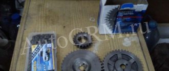
Location of camshaft drive and oil pump parts.
Install the drive mechanism parts in reverse order. Having installed the key in the groove of the crankshaft, we put on the sprocket.
. and press it onto the crankshaft, tightening the pulley mounting nut with a wrench.
Having unscrewed the nut, we press the sprocket with a tool head of a suitable size (a piece of pipe).
Before installing the chain, align the mark (mark above the keyway) on the crankshaft sprocket with the mark (protrusion) on the cylinder block.
. and the mark on the camshaft sprocket with the mark on the shaft bearing housing. Having installed the chain and hydraulic tensioner, turn the crankshaft clockwise two turns and check that the alignment marks match. We install the removed parts in reverse order.
Replacement of timing chain and sprockets (engineer) Niva VAZ 21213, 21214, 2131 lada 4×4
Remove the cylinder head cover (see here).
Rotate the crankshaft until the mark (hole) on the camshaft sprocket coincides with the mark on the camshaft bearing housing.
Remove the crankshaft pulley (see here). Disconnect the camshaft sprocket with the chain from the camshaft (see here). Remove the chain from the sprocket.
For clarity, we show the chain removal operations on a dismantled engine.
We unscrew the three bolts securing the oil pan to the camshaft drive cover (see here).
Using a 10mm socket, unscrew the three nuts and six bolts securing the camshaft drive cover to the cylinder block.
A “ground” wire is secured under one nut (on the left side).
Remove the camshaft drive cover.
. and a sealing gasket.
Using the “17” head, unscrew the axis of the hydraulic chain tensioner shoe.
We take out the tensioner shoe.
Remove the chain from the crankshaft sprockets and the oil pump drive shaft.
We take out the camshaft drive chain.
Using a puller, press the sprocket from the toe of the crankshaft.
The sprocket is fixed on the crankshaft with a segment key. To remove the key.
. Carefully, trying not to damage the key and shaft, use a chisel to knock it out of the groove of the crankshaft.
Using a chisel, loosen the bolt securing the oil pump drive shaft sprocket.
Using a 17mm spanner, unscrew the sprocket mounting bolt. We hold the sprocket from turning with a screwdriver resting through the hole in the sprocket on the head of the bolt securing the thrust flange of the roller.
. and the oil pump drive shaft sprocket.
Location of camshaft drive and oil pump parts.
Install the drive mechanism parts in reverse order. Having installed the key in the groove of the crankshaft, we put on the sprocket.
. and press it onto the crankshaft, tightening the pulley mounting nut with a wrench.
Having unscrewed the nut, we press the sprocket with a tool head of a suitable size (a piece of pipe).
Before installing the chain, align the mark (mark above the keyway) on the crankshaft sprocket with the mark (protrusion) on the cylinder block.
. and the mark on the camshaft sprocket with the mark on the shaft bearing housing. Having installed the chain and hydraulic tensioner, turn the crankshaft clockwise two turns and check that the alignment marks match. We install the removed parts in reverse order.