Home / Articles / Connecting a fuel level sensor
The cost of the service is 2,000 rubles.- Installation of a fuel level sensor (calibration, calibration) - RUB 3,500.
- Transport monitoring server including SIM card - 300 rubles. per month from one object.
To ensure control of fuel consumption during vehicle operation, it is necessary to install and connect a fuel level sensor.
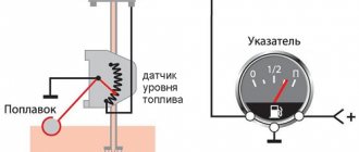
Structurally, the FLS is a rheostat, which is located in the fuel tank. As the fuel level changes, its resistance changes. The resistance value is converted into volume units, and this data is transmitted to a pointer located on the dashboard. You can install the sensor on a VAZ vehicle, as well as simple cargo vehicles (for example, KAMAZ) or specialized equipment yourself using simple equipment and tools. The answer to the question of how to connect a fuel level sensor will also not cause any difficulties - the circuit is quite simple.
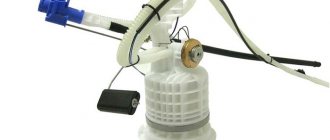
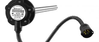
Fuel intake module with fuel level sensor GAZelle Next.
Fuel intake module with fuel level sensor GAZelle Next.
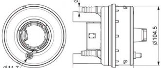
The fuel intake module A31R32.1139010 or A31R32.1139020 with a fuel level indicator sensor is designed to take fuel and ensure control of its level in the fuel tank.
The fuel intake module is installed inside the fuel tank. The module consists of an intake chamber, a module cover with fittings and a connecting block, a fuel pre-cleaning filter and a fuel level indicator sensor, consisting of a float connected to a rheostat. Depending on the amount of fuel in the fuel tank, a current is supplied to the electric fuel level indicator (in the device composition), which is determined by the resistance of the module’s rheostat.
The resistance of the rheostat depends on the fuel level and the position of the float.
| level in the tank, mm | Float position (N), mm | Resistance, Ohm |
| Empty tank | 10±2 | 330±15 |
| 1/8 | 30,2±2 | 230±10 |
| 1/4 | 57±2 | 185±10 |
| 1/2 | 107,4±2 | 118±10 |
| 3/4 | 157,4±2 | 65±5 |
| Full tank | 206,6±2 | 11±4 |
When the reserve fuel remaining in the fuel tank is reached (at least 10 liters, rheostat resistance 230±10 ohms), a signal lamp for the reserve fuel balance is turned on in the device arrangement.
The fuel intake module is a non-repairable item.
The fuel intake module must be replaced under the following criteria:
- if, when the lever moves smoothly up and down, the fuel level sensor circuit breaks;
- if the resistance when connected to the external electronic connector of the module at the upper (full tank) and lower (empty tank) levels does not meet the requirements (see table).
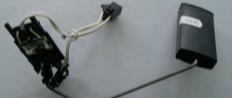
Fuel intake modules.
H – float position; 1 – anti-tide glass; 2 – pressure ring; 3 – fuel level sensor float; 4,5,6 – fittings.
Correspondence of contacts to electronic circuits.
| Contact designation | Name of electronic circuit |
| X 1:1 | Fuel level indicator |
| X 1:2 | Empty |
| X 1:3 | Empty |
| X 1:4 | Minus fuel level indicator |
Electronic circuit for connecting the fuel level indicator sensor.
R – rheostat of the fuel level sensor.
The gas sensor on the gazelle did not work.
Placement of contacts of connector X1.
Installation and operation instructions.
Removal and installation of the fuel intake module must be carried out with the fuel tank removed from the vehicle.
When replacing a faulty fuel intake module, do the following:
- After opening the package, inspect the module for damage to the housing and fitting tips, check the integrity and ease of movement of the fuel level sensor lever with the float.
- Install the module into the fuel tank of the car, having previously installed the O-ring. Rotate the module's clamping ring using a device with a torque of about 200 N m (20 kgf m), ensuring the tightness of the fuel tank.
Before tightening the pressure ring, the alignment arrows on the fuel pickup module and the fuel tank must be aligned (orientated towards each other).
- connect the module to the fuel lines of the engine power supply system and the fuel line of the afterheater or pre-heater, heater installed on the fuel tank, ensuring the correct installation of the fuel supply and fuel drain lines and the tightness of the connections. Connect the tubes to the module until a corresponding click appears. Secure the additional fuel intake pipe to the fuel tank with mounting bushings.
The connections of the fuel tank with the fuel intake module, fuel pipes and filler pipe must be sealed at an air pressure of 25-35 kPa (0.25-0.35 kgf/cm2) for 30 seconds in a bath of water. Air bubbles are not allowed. Check the density with the fuel pipes, filler pipe and valve with filter plugged.
- Connect the fuel tank wiring harness connector to the fuel intake module.
For vehicles with a heating system pre-heater or pre-heater, heater.
DIY repair
If the sensor is equipped with a porous component, there are several options for changing it:
- You can remove it from the retainer socket and install a new one, securing it.
- Or replace the float itself along with the rod.
The second option is more preferable because it is easy to implement. If the surface of the strip on the rheostat scale is dirty, the element is cleaned.
The cleaning procedure is performed exclusively with cotton wool or a soft cloth pre-treated with alcohol. The use of harsh materials or other products is not permitted. This will damage the working layer of the scale; it is quite thin, so it can cause the rheostat to break. The element cannot be repaired; it will have to be replaced.
If the contacts of the electrical circuit come off the controller, they must be carefully soldered back or connected at the point of damage. Plates with mechanical damage (cracks, fractures) cannot be repaired, only replaced. If the sensor gives incorrect readings, the problem can be corrected by adjusting the angle on the so-called rod. This element is designed to fix the float. To get accurate readings, the angle is bent in different directions.
Connecting the fuel level sensor
To ensure control of fuel consumption during vehicle operation, it is necessary to install and connect a fuel level sensor. Structurally, the FLS is a rheostat, which is located in the fuel tank. As the fuel level changes, its resistance changes. The resistance value is converted into volume units, and this data is transmitted to a pointer located on the dashboard.
READ The raised hand of the driver of a passenger car is
You can install the sensor on a VAZ vehicle, light trucks (for example, KAMAZ) or specialized equipment without the help of others using conventional equipment and tools. The answer to the question of how to connect a fuel level sensor will also not cause any difficulties - the circuit is quite simple.
How to properly connect a car fuel level sensor with a ground switch
If the car is equipped with a mass switch, two options for connecting the fuel level sensor can be used:
- connection behind the mains switch. It should be taken into account that in this case, when the mass is turned off, the sensor will be de-energized. The indicator will show the latest fuel level data that was recorded during vehicle operation. After turning on the sensor, this data may change. Prerequisites include daily temperature fluctuations, deformation of the fuel tank, or fuel drainage while the car is parked. With all this, it is unrealistic to establish the time of drainage (and, accordingly, to directly substantiate its fact). If a cheap sensor , the connection diagram of this type is completely suitable. In this case, there is no need to use galvanic isolation. It is also recommended if the car battery is often removed or missing;
- connection specifically to the battery. It is recommended to use modern electrical sensors with built-in galvanic isolation. It protects equipment from exposure to electric current in an emergency. If there is no integrated galvanic isolation, it must be installed additionally. Connecting a fuel level sensor according to this scheme is considered good in terms of multifunctionality and practicality. In addition, it is considered non-hazardous because the device consumes current in the range of 10–48 milliamps. The sensor body is made of non-conductive material, which protects electrical circuits from current breakdown.
Ultrasound category
Meters in this category are designed on the principle of emitter-type devices. A wire is attached to the sensor, which transmits information to the tracker (GPS). The structure is placed on the outer wall of the tank. It is important to understand the principle of ultrasonic FLS analysis. The device creates a wave pulse (ultrasonic type), which is sent directly into the liquid, overcoming the wall of the container. Reaching the point of contact between air and liquid, the signal is reflected and recorded using a meter. Calculation of fuel volume indicators is made based on the time spent reflecting the impulse.
The accuracy of such technology is an order of magnitude superior to float devices, but a number of specifics must be taken into account. These specifics include the following:
- The contact between the sensor and the wall of the container does not allow deviations. Otherwise, the pulse will be propagated incorrectly.
- Installed structures inside the container will affect the correct propagation of the pulse. In addition, the material of the reservoir also affects the quality of ultrasonic analysis. It is not recommended to install the ultrasonic meter on a tank that contains additional baffles.
- The quality of the analysis will suffer if there are defects (mechanical damage) on the surface of the container. Lumps, chips, and roughness will directly affect the measurement.
- The bottom sediments of the tank also affect the quality of the analysis. Accumulated particles interfere with the propagation and reflection of the ultrasonic wave.
In addition, installation of this type of device will require the intervention of professionals. It is not recommended to install ultrasonic equipment yourself.
This model is available for sale at a price of 8.5 thousand rubles (on average), installation will require from 3.5 to 6 thousand rubles. The model features a notable fastening technology that eliminates drilling of the tank. The manufacturer excluded direct contact of the device with liquid, and also equipped this specimen with technology that eliminates the risk of fire. Users note the high accuracy of the analysis and the ability to connect the device to both Glonass and GPS.
“An excellent device that takes fairly accurate measurements. The absence of drilling provides additional tightness; the sensor does not come into direct contact with the liquid. I recommend it to anyone looking for a quality FLS!”
The company's wide range of devices for different categories of equipment is noteworthy. Devices for agricultural machinery, professional transport, and passenger cars are available under this brand. For convenience, the model is equipped with a centralized data collection system, which allows you to record any operations related to the replenishment or consumption of fuel.
“It’s a good device, the measurements are accurate, the control system is convenient. Although similar equipment can be purchased cheaper, the model shows strong quality worthy of the assigned price tag. I recommend it to anyone looking for a reliable sensor!”
The model in most aspects corresponds to its predecessor (Uzi-0.8), but taking into account the correction of imperfect mechanics. The improved version of the sensor from Sensor increased in price by 4 thousand rubles. and costs from 12 thousand rubles (on average). For this price, the user receives an improved ultrasonic testing system and a number of guarantees from the manufacturer. With appropriate connection, the sensor is capable of autonomous operation for up to 30 days, which is useful for drivers who stop for long periods of time.
“I purchased this model because I often stop for long periods of time. For such events, it is necessary to have a fuel monitoring device, because drains occur regularly without my knowledge. I recommend it to anyone who is looking for an FLS with the ability to operate autonomously!”
Fuel level sensor - general connection diagram
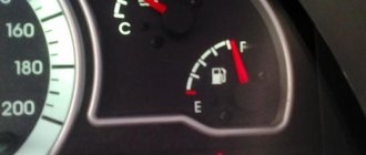
After installing the device in the fuel tank, you need to connect it to the vehicle's on-board network. A cable is connected to the sensor, which connects to a gauge on the dashboard. For a high-quality connection, it is recommended to use special connectors, and insulate the connection points with corrugation or electrical tape. After connecting the fuel level sensor according to the diagram, it is necessary to fill the tank with fuel and check the correct operation of the device. The value on the indicator must correspond to the actual volume of gasoline poured.
Connection diagram for GAZelle fuel level sensor
Electrical diagram of GAZ-3302.2705 cars
GAZ-3302.2705 - “Gazelles” of the earliest production were equipped with engines from the Zavolzhsky Motor Plant with a power of 100 hp. and Ulyanovsk plant, respectively 90 hp. The wiring of these models partially differs from models with injection engines in the part where the ignition systems are described and in additional sections of the control sensor circuits.
In order to download electrical circuits for GAZ-3302.2705. left-click on the picture, then click on the “full size” arrow and right-click on “save as...”
- side turn signal indicator;
- turn signal indicator;
- headlight blocks;
- front position lamps;
- lamp (high-low) headlights;
- toggle switch for rear interior lighting (for vehicles with two-row seats);
- lighting of the engine compartment;
- lighting fixtures for the rear part of the cabin (for vehicles with two-row seats);
- cabin lighting lamp in the front;
- lampshades (canopy lamp for GAZ-2705 and GAZ-27057 with two-row seating) of the cargo compartment;
- starter relay;
- central block of fuse links;
- electric generator;
- starter location;
- battery;
- positive battery terminal switch;
- remote control button for battery switch;
- parking brake warning light relay;
- egnition lock;
- handbrake signal switch;
- brake fluid level warning lamp sensor
- temperature sensor of antifreeze coolant (water);
- antifreeze (water) temperature sensor;
- oil pressure visual monitoring device sensor
- oil pressure warning light sensor;
- Toggle switch for fog lights;
- main switch for external lighting modes;
- lower fuse block;
- switch for the electric pump of the heating system (GAZ-33023;.330273);
- electric pump for the heating system (GAZ-33023;.330273);
- electric windshield washer motor;
- signal location;
- socket for connecting a portable flashlight;
- platform lamp (GAZ-3302;.33021;.33027);
- driver signal buzzer (GAZ-3302.33021.33027);
- buzzer switch (GAZ-3302.33021.33027);
- hazard warning light button;
- turn signal relay;
- upper fuse block;
- device for switching operating modes of turn signal indicators;
- control panel;
- device for monitoring the fuel level in the tank;
- lamp indicating fuel reserve in the tank;
- voltmeter;
- speedometer;
- daily mileage counter;
- turn signal indicator lamp (green);
- indicator lamp of an emergency drop to a critical level of brake fluid and a raised handbrake lever (red);
- battery low indicator lamp;
- indicator lamp for turning on the center differential lock of the transfer case (for all-wheel drive 4x4 models);
- antifreeze (water) overheating indicator lamp (red);
- side light indicator lamp (green);
- headlight high beam indicator lamp (blue);
- tachometer;
- oil pressure indicator;
- emergency (critical) oil pressure indicator lamp (red);
- temperature indicator of antifreeze (water);
- brake signal button;
- button for automatic reversing signal;
- center differential lock signal switch (for 4x4 all-wheel drive models);
- location on the diagram of the fuel sensor that controls the level ;
- device for switching operating modes of the electric motor of the additional heater and the electric pump of the heating system (for vans with two rows of seats);
- resistor for the electric motor of the additional interior heating radiator;
- radio;
- multifunctional cigarette lighter socket;
- multi-position toggle switch for the electric motor of the stove fan;
- electric heating pump (for vans with two rows of seats);
- electric motor for additional interior heating radiator;
- electric motor for interior heating radiator;
- heater electric motor resistor;
- location of the relay controlling the windshield wiper drive;
- electric wiper motor;
- device for switching operating modes of the windshield wiper;
- combined rear lamp;
- location of turn signal lamps;
- position of side light lamps;
- brake signal lamp;
- reverse lamp;
- rear fog lamps;
- number plate illumination;
- ignition coil (high-voltage coil);
- candles;
- distributor with vacuum ignition timing drive
READ Where is the speed sensor located on Renault Logan
Electrical diagram of GAZ-3302.2705 with engines ZMZ-402, UMZ-4215
Additionally, look at the wiring diagram of the GAZelle with a new panel (405 engine):
Wiring diagram of full quality and with description (4, 51 MB) - download HERE.
The 405 motor control circuit is shown as an example. With full quality and description (1.35 MB) - look HERE.
GAZelle until 2009. Electrical circuits - part 1
Diagram of the engine control system UMZ-4216, ZMZ-40522: 1 – electronic unit of the engine control system; 2 – phase sensor ( camshaft position sensor 3 – crankshaft position sensor; 4 – throttle position sensor; 5 – sensor ; 6 – mass air flow sensor; 7 – coolant temperature sensor 8 – air temperature sensor in the intake pipe; 9 – sensor (for engines with a catalytic converter); 10, 11, 12 and 13 – nozzles; 14 – idle speed regulator; 15 – canister purge valve (for a car with a fuel vapor recovery system); 16 – fuel pump relay; 17 – fuel pump electric motor; 18 – engine control system relay; 19 – diagnostic connector; 20 – block for connection to the tachometer; 21 – block for connecting the engine control system to the vehicle’s electrical network; 22 – relay for turning on the electromagnetic fan clutch; 23, 26 – ignition coils; 24, 25, 27 and 28 – spark plugs; a – connection diagram of injectors on a car with a UMZ-4216 engine (1, 2, 3 and 4 injectors)
Diagram of electrical equipment of cars with UMZ-4216, ZMZ-40522 engines: 1 — left side direction indicator; 2 — left headlight; 3 — right headlight; 4 — right side turn signal; 5 - starter; 6 — fuse box (in the engine compartment); 7 — headlight relay; 8 - central lighting switch; 9, 10 — lampshades for cargo compartment lighting (for vans); 11 — canopy lighting for the front part of the cabin; 12 — windshield washer motor; 13 — courtesy lamp for the rear part of the cabin (for vehicles with two rows of seats); 14 — switch for the interior lighting of the rear part of the cabin (for vehicles with two rows of seats); 15 — platform lamp (GAZ-3302, -33021, -33027); 16 — buzzer switch (GAZ-3302, -33021, -33027); 17 — driver signal buzzer (GAZ-3302, -33021, -33027); 18 — sound signals; 19 — sound signal relay; 20 — ignition switch; 21 — starter relay; 22 - generator; 23 - battery; 24 — battery switch; 25 — remote battery switch button; 26 — electric drive of the heater valve; 27 — electric pump for additional heater; 28 — heater electric fan resistor; 29 — heater fan electric motor; 30 — heating and ventilation control panel (1 — heater tap switch; 2 — backlight lamp for the heating and ventilation control panel; 3 — relay; 4 — main heater electric fan switch; 5 — electric fan and auxiliary heater electric pump switch); 31 — upper fuse box (in the cabin); 32 — lower fuse block (in the cabin); 33 — engine compartment lamp; 34 — hazard light switch;
READ Replacing the parking brake cable on a VAZ 2115
35 — radio receiver; 36 — resistor of the additional heater electric motor; 37 — additional heater electric motor; 38 — interior lamp switch (right side); 39 — interior lamp switch (left side); 40 — lamp for lighting the steps (for buses); 41 — interior lamps (right side); 42 — interior lamp (left side); 43 — cigarette lighter; 44 — switch for checking the serviceability of signaling devices; 45 — sensor for emergency drop in brake fluid level; 46 — right steering column switch (switch for direction indicators and headlights); 47 — direction indicator relay; 48 — switch for electric headlight correctors; 49 — parking brake warning switch; 50 — parking brake warning relay; 51 — lighting control of the instrument cluster; 52 — connector (wire block) for connecting the ABS system; 53 — instrument cluster; 54 — brake signal switch; 55 — switch for the glove compartment lamp; 56 — glove box lighting; 57 — fuel module; 58 — center differential lock warning switch (for 4x4 vehicles); 59 — windshield wiper control relay; 60 — engine control system pads; 61 — coolant temperature indicator sensor 62 — coolant overheat indicator sensor 63 — windshield wiper; 64 — oil pressure indicator sensor 65 — emergency oil pressure indicator sensor 66 — right steering column switch (horn and windshield wiper switch); 67 — speed sensor; 68 — reverse light switch; 69 — rear light (right); 70 — license plate lights; 71 — rear light (left)
Tips for motorists
The operating principle of fuel level sensors on all GAZelle vehicles is almost the same. The sensor itself is a rheostat, the movable contact of which moves the float using the lever on which it is attached. The sensor works in tandem with a fuel level indicator located on the instrument panel. With zero resistance in this electrical circuit, the fuel gauge arrow should indicate that the fuel tank is full. Well, when the float, following the fuel level, begins to fall down, the resistance of the rheostat begins to increase, and the indicator needle begins to move towards zero as gasoline is consumed. This is how a working fuel level sensor should work.
The first reason why this sensor begins to “fail” is poor contact of the wire going to the ground of the car. You should know that the fuel tank itself is isolated from the “mass” of the car, since insulating gaskets are installed under the metal tank mounting clamps (in addition to metal tanks, Gazelles can also have plastic fuel tanks). Therefore, it is necessary to carefully monitor where the negative wire goes. Find the place where it connects to the vehicle ground and check the tightening of the fastening screw.
If GAZelle cars have an injection engine and the electric fuel pump works normally on it, this means that everything is in order with the wire going to ground, since the ground leads from the fuel pump and the fuel level indicator sensor go to the same contact of the fuel pump block.
The second reason why sensor is poor contact of the rheostat slider with the nichrome spiral winding along which it moves when the fuel level in the tank changes. To eliminate this malfunction, it is necessary to remove this sensor from the fuel tank, disassemble it and bend the contacts of the slider so that they touch the surface of the nichrome spiral of the rheostat along the entire length of the slider stroke.
In addition to electrical malfunctions of the fuel level sensor, a purely mechanical malfunction may also occur, consisting of a leaky float. fuel gets inside the float and as it accumulates in it, the float cannot float above the fuel level in the tank, which means that the fuel level indicator will not give correct readings. Once the float is completely filled, the fuel level indicator will always indicate that there is no fuel in the tank.
Sources:
https://gpsmcard.ru/stati/podklyuchenie-datchika-urovnya-topliva/ https://litezona.ru/shema-podkljuchenija-datchika-urovnja-topliva/
FLS installation process
FLS installation is carried out by partners in 100% of cases. Clients, as a rule, do not have the qualifications, experience and desire to install FLS on their own. The reasons for reluctance are not only technical, but also organizational and social (obstruction of innovations in control, sabotage and vandalism of drivers, etc.).
To install the FLS you must have:
- A team of 2 people (it is difficult for one person, for example, to dismantle the tank)
- Tools Bimetallic crown for metal (often with a diameter of 35mm)
- Angle drill
- Metal drills (often titanium nitride, yellow)
- Phillips and slotted screwdrivers
- Pliers (nippers, pliers, etc.)
- Hacksaw or pipe cutter
- Riveter (for securing the FLS to thick-walled tanks)
- Calibration tube
As a rule, professional installers have a special technical vehicle. It contains tanks for draining fuel and a station for pumping fuel.
In addition to equipment, you need to have theoretical training and experience in solving non-standard situations.
Now let’s take a closer look at the installation process of each type of FLS.
Ultrasonic FLS
To install, you need to clean the area outside the bottom of the tank, glue the FLS there and secure it with a clamp placed around the tank. After this, the power supply is connected to the FLS and calibration is performed.
- The ultrasonic FLS is installed externally at the bottom of the fuel tank. For installation, the geometric center of the tank bottom is selected.
Operating time is approximately 4 hours.
Capacitive FLS
To install a capacitive FLS, you need to remove and evaporate the fuel tank, make a hole at the top of the tank, insert the measuring part of the FLS into it and secure the FLS with self-tapping screws to the surface of the tank. After this, the power supply is connected to the FLS, calibration and calibration are performed.
- Before installation, all fuel must be drained from the tank. Then you need to get rid of the fuel vapors remaining in the tank after draining the fuel. If this is not done, then when drilling a hole, an explosion will occur due to a spark (especially after using gasoline). To do this, the tank is dismantled, water is poured into it, drained (repeat), and then evaporated (the process is called “tank evaporation”).
- For installation, the geometric center of the tank is selected.
- A hole is made in the geometric center of the tank; metal shavings should not fall into the tank.
- The measuring part of the FLS is cut slightly shorter than the height of the tank - this way fuel can freely flow between the tank tubes. For trimming, use a pipe cutter or a hacksaw.
- Calibration in progress. This will allow the FLS to know its new length after trimming. To do this, the FLS is turned over with the measuring part up and completely filled with fuel. After 1-2 minutes, the fuel is drained.
- The capacitive FLS is installed in the hole made so that the measuring part is inside the tank, and the board with the interface cable is outside.
- The sensor is fixed to the surface of the tank with self-tapping screws. There are holes in the metal base of the top of the sensor on which the board is attached for self-tapping screws.
- The FLS is connected to the vehicle's on-board electrical network and to the computer. A special adapter is used for this. Software for setting up the FLS is installed on the computer.
- Calibration is in progress.
- The FLS is disconnected from the computer and connected to the tracker. Tracker installation is complete.
Operating time is approximately 4 hours. Training video from Omnicomm (10 minutes)
Connection to CAN bus
To connect to the CAN bus, you must first find it in the car. The CAN bus is two wires twisted into a twisted pair. There are many wires in a car, and there may be more than one CAN bus. Therefore, it is very difficult to find the right CAN bus without documentation about where it goes.
When it is found, a “CAN crocodile” is used to read the data (recommended) or connected directly to copper wires (less preferable).
Source