Internal combustion engines are far from perfect, so most of the energy consumed during the operation of such units is released in the form of heat. In the winter season, this “by-product” can be successfully used to maintain optimal air temperature in the cabin, but in the summer this is not necessary, so antifreeze can boil even after a short period of operation of the internal combustion engine. When the coolant heats up to a certain value, the fan automatically turns on and the coolant temperature returns to normal. The VAZ 2110 fan switch-on sensor, with the help of which the forced cooling of the internal combustion engine is timely activated, will be discussed in this article.
Design and principle of operation
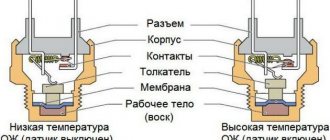
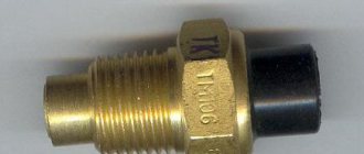
The VAZ 2110 fan sensor, both 8 and 16 valves, consists of a sealed housing, inside of which there is a bimetallic plate and electrical contacts. A feature of the working element is the possibility of significant physical expansion when heated. When the temperature changes significantly upward, the plate expands and the thermal relay contacts close.
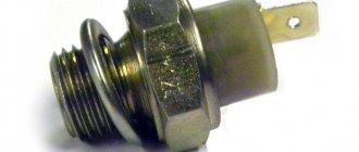
On the outside of the housing, a thread is cut, which is necessary for reliable fixation of the sensor in the cooling system of the internal combustion engine. On the opposite side of the sensor, terminals are installed that are necessary for connecting the contact wires.
Replacing the bimetallic thermal switch
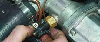
Replacing the fan switch sensor begins by removing the terminal with the “-” sign from the battery. After this, you can begin to drain the coolant from the system. At the end of this process, you need to turn off the power to the sensor and unscrew it from the radiator housing. Assembly is carried out according to the same algorithm, but in the opposite direction. It is imperative to check the sensor for functionality.
The cooling fan design of an internal combustion engine is one of the main components of the successful functioning of the entire vehicle system. It is through this means that it is possible to forcefully organize airflow of the engine, which was very hot, and the radiator during the immediate periods when the vehicle is parked, provided that the engine is turned on and running.
The history of the entire cooling system of a car, it would seem, is quite meager, as a result of which the development of all the necessary devices followed two main paths. It is on the basis of these considerations that it can be determined that production cars in the modern world use two main types of cooling systems: liquid cooling
and
air cooling.
The fan, as the main combined device, which is the basis, is used in both cooling systems. This type of design is based on the functional components and operating principle of the vehicle cooling system.
The fact is that the final medium that dissipates the heat that is removed from the internal combustion engine is air
. Consequently, it is the fan device that plays the role of a connecting element, which is the main source of ensuring a constant and uniform process of heat removal directly into the atmosphere.
How does the fan temperature sensor work?
During those periods of the year when the weather outside is quite hot, there are quite often cases when the engine of even a good modern car overheats. In order to prevent this on the road, the motorist should very closely monitor the operation and condition of the system, which is responsible for cooling the internal combustion engine. It is important to note that as the temperature of the cooling liquid increases, the use of natural cooling will not be sufficient; therefore, in order to increase the heat removal from the car by an order of magnitude, you will have to turn on additional fans that are installed directly on the device.
It is this kind of switching on of devices, if the temperature has reached a critical state, that will be supervised by a sensor that is installed on the lower part of the radiator device. That is why it is important to say that the fan sensor is the key to the successful functioning and operation of the car and it plays an important role in the health of the vehicle when traveling in the summer.
These types of sensors have a fairly simple design and functional design. The lower part of such an element has a bimetallic plate in its arsenal, which is designed to be dismantled when a certain temperature is reached, as a result of which a certain impact will occur directly on the pusher, through which the contacts will be closed.
For a more detailed consideration of this issue, you should refer to the fan switching system itself. While the liquid that is located in the radiator is cold, the plate, which is bimetallic, will be in a calm state inside the sensor, as a result of which the contacts will be open. At a time when the temperature of the liquid rises to the required set level, the bimetallic plate device will be deformed.
After this, it will push the pusher, through which the contacts will close.
It is also important to note that different cars will have different installed sensors, which will be adjusted to different response temperatures, which directly depends on the design of the engine, its power and other equally important characteristics. In addition to the classification that is attributed to the sensor and which lies in the temperature at which the fans turn on, these devices can be divided into two types, the classification principle of which will be different rotation speeds: those that are designed for one turn-on speed; those that are designed for two speeds.
Most modern cars have a single-speed fan system. However, it will not be very uncommon to find a two-speed system. This kind of system, when a certain temperature is reached, will react in a unique way, since one pair of contacts will close directly on the sensor itself.
It is through this action that the fan will be activated at low speeds. If the temperature of the cooling liquid rises, the sensor will automatically close the second pair of contacts, as a result of which the fans will rotate at maximum speed, which will remove a fairly large amount of heat.
Replacing the fan temperature sensor
Such a need arises when a motorist notices that this system is not working properly and may indicate incorrect indicators, as a result of which the engine may be seriously damaged, causing enormous damage to the motorist’s wallet. Timely replacement of the fan switch sensor should be carried out using the simplest set of plumbing tools. All work carried out must be divided into three blocks.
The first step is to drain the coolant directly from the radiator, as a result of which you need to de-energize the radiator switch itself.
After this, it is necessary to remove the device itself from the radiator housing. Next, you should simply install the new device, using a copper sealing ring.
It is important to note that before directly installing the product, you need to do a little prank. It is necessary to connect the terminals on the fan switching sensor to the terminals of the output contact, which belong to the megger. This is how you can test the functional part of this product.
Control over the inclusion of a working product should be done using heated water, where the sensor itself will need to be placed. In this case, the following should happen: the contact terminals of the device should close. If the temperature reaches 95 degrees, the megger device should indicate the resistance of the product, which indicates that the device is working normally.
Malfunction of the fan temperature sensor
It is not uncommon for cars that are domestically produced to experience a failure of the fan switch sensor. It is important to note that if a motorist notices this kind of malfunction, a sign of which will be the temperature scale arrow exceeding its value, you can safely determine the cause of overheating - the fan switch on sensor.
If this device malfunctions, then the driver will have to drag it to the garage, which will not be difficult to do. It is necessary to remove the connector from the sensor, and using a small piece of wire, a paper clip, or any other part that comes to hand, you will need to close the terminals in the connector, as a result of which the fans will start. After this, if enabled, these devices will rotate constantly.
To check the unscrewed sensor, you will need the following procedure. First you need to take a shallow pan, a 100 degree thermometer or multimeter to test the sensor. Next, you need to hook up two wires directly to the sensor and hook up the wires to the ends of the multimeter. You need to pour water into the pan. Next, you need to hang the sensor on a thread and secure it. It is important to note that the entire metal part must be in water. There should be no direct contact between the pan and the sensor.
Thus, heat will be transferred to the sensor only through water. That is why water must fill the pan so that the sensor device does not touch the bottom.
Next, you need to turn on the gas stove burner so that the water heats up gradually and slowly. It is when the water is gradually heated over low heat that it is necessary to monitor the response of the sensor, and then compare the results of the experiment itself with the readings on the sensor.
Subscribe to our feeds at
Symptoms of a problem
If the engine boils, and the characteristic hum of the cooling system fan is not heard, then with a high degree of probability one can suspect the presence of a malfunction of the internal combustion engine. The opposite situation, when forced cooling operates as long as the ignition is on, will also indicate a problem with the automation. On a VAZ 2110 injector, a constantly switched on fan sensor may indicate problems with the controller. The control unit could “remember” an error that appeared earlier and, as a result, the electric motor is activated every time it is started.
Periodic turning on and off of the fan when the engine is not yet warmed up is also a sure sign of an imminent failure of the combustion engine.
Fan
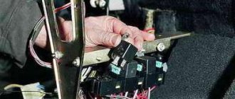
If the problem lies in the injector or carburetor cooling fan, then you will have to remove it. It is quite possible to repair the unit by replacing the electric motor or impeller.
Diagram with casing, radiator, fan and impeller
To remove the valve, perform the following operations:
- Disconnect the negative terminal from the battery;
- Disconnect the wire terminals. One of them is mounted on the fan casing;
- Take a wrench and unscrew a couple of connecting bolts. They fix the vent casing on the left tank;
- Next, unscrew another lower nut holding the device casing;
- Now you will need a socket extension to unscrew the right nut on top that secures the vent housing to the radiator;
- All that remains is to unscrew the fan pressure plate. To do this, remove the pair of left nuts;
- Remove the pressure plate by hand;
- Now remove the fan along with the casing.
You have removed the unit. Now you have a choice - change the entire unit, or try to repair it by replacing the electric motor or impeller if they are damaged.
Replacing the electric motor
- Disconnect the fan motor wire that is held in place by a clamp on the casing.
- The electric motor is held on the casing by three nuts. They all need to be unscrewed.
- Remove the electric motor from the fan housing.
- Be sure to check the condition of the rubber bushings of the electric motor, which will remain on the casing. If cracks or signs of deformation are detected, they must be replaced.
- Check the electric motor for functionality. If it fails, you can purchase a new one and insert it into the old casing.
Electric motor
It is not uncommon for the radiator fan to malfunction due to a deformed impeller. By replacing it, you can restore functionality to the device.
Replacing the impeller
To change the impeller, follow the instructions:
- Pry up the lock washer using a flathead screwdriver. It is located directly in the center of the impeller;
- Lift the washer and remove it;
- In some cases, the impeller is secured to the fan motor with a nut. Therefore, if you have one, unscrew the mount;
- Remove the impeller and assess its condition. If it is worn out or deformed, replace it with a new one;
- Many people, instead of a standard 4-blade impeller, install a more advanced 8-blade impeller.
Changing the impeller
During the reassembly process, make sure that the electric motor pin fits into the longitudinal hole on the impeller, as indicated in the figure below.
Direct the pin into the longitudinal hole
Where is
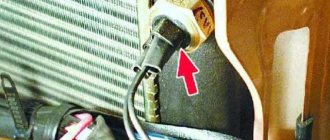
Drivers who have never encountered a malfunction in forced engine cooling before may not know where the internal combustion engine is located. On a carburetor VAZ 2110, this element of the cooling system is located on the radiator. If the driver finds this part, then he can easily find the fan switch sensor, which is located on the side. A characteristic feature of the product is the electrical wires connected to it. On the injection VAZ 2110, this part can be found on the cylinder block.
The sensor located in this way allows you to respond promptly to changes in coolant temperature. In addition, access to this part is not difficult and you can immediately begin repair or diagnostic measures if there are doubts about its performance.
Modernization
If you want to improve the operation of your radiator fan on the VAZ 2109, we offer the appropriate instructions.
To upgrade, you will need to install a second sensor and modify the system somewhat.
- The standard power sensor will be responsible for the operation of the fan at maximum speed.
- An additional sensor will include a reduced speed. It is installed at the top of the cooling system.
Now let’s talk more specifically about how to organize all this.
- Take a temperature sensor whose response temperature is similar to the standard regulator.
- Install it in the upper pipe fitting to the radiator.
- To mount the element, you will need a pair of washers and a nut. Be sure to lubricate the washer with sealant to prevent leakage from the installation hole.
- Buy a resistor to install on the stove fan. It has several outputs, so if desired, you can make several operating speeds.
- It is necessary to make an additional control circuit. Through it, less voltage will be supplied to the motor winding.
- The temperature sensor located in the upper part of the cooling system is responsible for turning it on.
- It is better to do control not by plus, but by weight.
- The system will work through a button in the cabin. To the left of the dashboard there is a grille with two plugs. Cut out one of them and set it to turn off on two modes. You can take the heater switch from a VAZ 2107.
- In the first position the low frequency will be switched on, and in the second – the maximum speed.
- One common wire is fed to the minus.
Such modernization is not provided for by the design of the VAZ 2109. These are modifications made by car enthusiasts. Therefore, installing a second sensor is entirely your personal responsibility.
The fan is an important component of the cooling system of VAZ 2109 injection and carburetor engines. If you wish and have time, you can easily replace or repair it yourself.
How to replace
The fastest and easiest way to find out the reason for the fan not turning on or running continuously is to replace the DVV with a known good product. To avoid further confusion, it is not recommended to use used products, as well as sensors purchased from unverified retail outlets.
To carry out work on replacing the internal combustion engine, it is necessary to prepare a new part, a set of wrenches, rags and a container for collecting coolant. The process of removing the old part and installing a new sensor is as follows:
- Place the car on a level surface.
- Disconnect the negative terminal of the battery.
- Unscrew the cap of the expansion tank.
- Disconnect the wires from the DVV.
- Place a wide container under the engine to collect coolant.
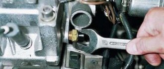
- Using a 30mm wrench, unscrew the faulty part.
- Install a new DVV.
- Connect wires to the sensor.
- Pour coolant into the expansion tank.
- Close the lid.
- Connect the battery.
After starting the engine, it must be allowed to run for 15–20 minutes. During this time, the coolant temperature will reach a level at which the thermal relay contacts close and the fan will begin to rotate.
A little theory
| Characteristic | Explanation |
| Location | The sensor is located in the heater radiator. It is not difficult to determine that this is the one in front of you, since in the radiator it is the only element to which the wires are connected. And if you take a 30 key, then only the sensor has the appropriate fastener size. |
| Response temperature | Sensors may have different temperature limits. But for the VAZ 2114, switching on occurs at 102-105 degrees Celsius, and switching off occurs at 85-87 degrees. When choosing a new meter, focus on the one that has failed, or purchase one with an on and off indicator of 102 and 87 degrees, respectively |
| Operating principle | There is a special contact group inside the sensor. When the coolant in the radiator heats up, this group heats up and expands. When the expansion reaches a certain limit, the contacts close, they transmit a signal to the wiring and the fan turns on |
Diagnostics of VDV
If, as a result of replacing the sensor, the functionality of the cooling system is not restored, then the new part may be defective.
To make sure that the DVV is working, you need to perform the following simple steps:
- Remove the sensor from the car.
- Place it in a metal container with water.
- Place the tank on the gas stove.
- Boil.
- Remove the DVV from the container and measure the resistance between the contacts.
You can use an inexpensive multimeter or tester to perform the diagnostic operation. If, as a result of measurements, the presence of insignificant electrical resistance is established, then the sensor is in working order and can be used for its intended purpose. How to check this part is now clear, so if you don’t find an inexpensive used part, you can also install it after a diagnostic operation.
Sensor check
First, we advise you to check the sensor that you think is faulty. Even if it turns out that it doesn't really work, at least you'll have peace of mind.
Plus, be sure to check the new sensor before installing it. This will make sure it works. Today there are quite a lot of fakes on the market, so there is always a chance to purchase a low-quality fan sensor.
Searched object
To check you will need a certain set of tools and materials, which includes:
- Capacity;
- Water;
- Coolant;
- Thermometer;
- Multimeter.
Let's start checking.
- Pour water or regular coolant into the prepared container.
- Lower the sensor into it with the threaded part.
- Connect the multimeter terminal to the regulator contacts. The measuring device must be in resistance measurement mode. Although if the multimeter has a dialing function, then choose it.
- Place a thermometer into the liquid.
- Heat the water.
- When the liquid temperature reaches the regulator response temperature (92 degrees Celsius), the contacts should close and the multimeter will start beeping.
- If this does not happen, the sensor really does not work and needs a replacement.
If you purchased a regulator that is not working, be sure to go to the store and ask for a replacement or refund. But only if you have a receipt. It is better to purchase spare parts in specialized, good stores. There is less risk of getting caught by a fake.
Tips and tricks
During the diagnostic operations and replacement procedure, some difficulties may arise that you should be aware of in advance, for example:
- The sensor may be fully operational and the wiring intact, but the fuse installed in this electrical circuit may fail. It is also recommended to replace this part with a new one in order to exclude it from the list of possible “culprits” for the fact that the VAZ 2110 fan does not turn on.
- You can diagnose the fan switch sensor without a multimeter or tester. It is enough to assemble an elementary circuit with a current source, a light bulb and a series-connected DVR, which will serve as a thermal switch.
The process of replacing the DVV VAZ 2110 is simple, so even if you have no experience in performing such work, you can perfectly perform this operation the first time without outside help.
Fan
If the problem lies in the injector or carburetor cooling fan, then you will have to remove it. It is quite possible to repair the unit by replacing the electric motor or impeller.
Diagram with casing, radiator, fan and impeller
To remove the valve, perform the following operations:
- Disconnect the negative terminal from the battery;
- Disconnect the wire terminals. One of them is mounted on the fan casing;
- Take a wrench and unscrew a couple of connecting bolts. They fix the vent casing on the left tank;
- Next, unscrew another lower nut holding the device casing;
- Now you will need a socket extension to unscrew the right nut on top that secures the vent housing to the radiator;
- All that remains is to unscrew the fan pressure plate. To do this, remove the pair of left nuts;
- Remove the pressure plate by hand;
- Now remove the fan along with the casing.
You have removed the unit. Now you have a choice - change the entire unit, or try to repair it by replacing the electric motor or impeller if they are damaged.
Replacing the electric motor
- Disconnect the fan motor wire that is held in place by a clamp on the casing.
- The electric motor is held on the casing by three nuts. They all need to be unscrewed.
- Remove the electric motor from the fan housing.
- Be sure to check the condition of the rubber bushings of the electric motor, which will remain on the casing. If cracks or signs of deformation are detected, they must be replaced.
- Check the electric motor for functionality. If it fails, you can purchase a new one and insert it into the old casing.
Electric motor
It is not uncommon for the radiator fan to malfunction due to a deformed impeller. By replacing it, you can restore functionality to the device.
Replacing the impeller
To change the impeller, follow the instructions:
- Pry up the lock washer using a flathead screwdriver. It is located directly in the center of the impeller;
- Lift the washer and remove it;
- In some cases, the impeller is secured to the fan motor with a nut. Therefore, if you have one, unscrew the mount;
- Remove the impeller and assess its condition. If it is worn out or deformed, replace it with a new one;
- Many people, instead of a standard 4-blade impeller, install a more advanced 8-blade impeller.
Changing the impeller
During the reassembly process, make sure that the electric motor pin fits into the longitudinal hole on the impeller, as indicated in the figure below.
Direct the pin into the longitudinal hole
VAZ cooling fan connection diagram
All the main electrical circuits and modifications for connecting the liquid cooling fan (CO) in VAZ cars of various models are provided. What is the essence of VO’s work? An electric motor with an impeller on a shaft is installed inside a rectangular metal frame, with which it is attached to the back of the radiator. When voltage (12 V) is applied to the contacts of the drive, it begins to work, rotating the blades and creating a directed stream of air, which, in fact, cools the antifreeze or antifreeze.
If the cooling fan does not work, do not rush to contact a car service. You can determine the cause of the malfunction yourself. Moreover, it is not at all necessary to have special skills for this - just study the reference material from 2shemi.ru and follow the instructions for checking/replacing it.
For carburetor systems
There are still many VAZ 2107 cars in use on the roads with a carburetor supply of the fuel mixture. As in the injector, engine cooling occurs thanks to the radiator and fan, only the process is regulated by a fan sensor.
Location and principle of operation
On older cars, additional cooling begins when the antifreeze reaches a certain temperature, usually 92 °C (there are differences for individual sensors). Carburetor systems are equipped with 2 coolant sensors - one to regulate fan operation, and the second sends readings to the driver’s instrument panel.
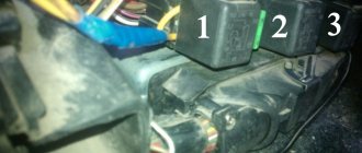
The sensor that turns on the fan is located on the bottom of the radiator panel, on the right side. To see it, you need to lift the hood and on the back you can see a “nut” with wiring. Usually these are modifications of the TM-108.
The principle of operation is to change the volume of the working fluid of the sensor when the temperature of its working fluid fluctuates. Inside the thick-walled steel housing is a working mixture covered with a flexible plate attached to a pusher that connects the contacts when the sensor is triggered.
In the steel case, the sensor heats up evenly, the working fluid expands and the contacts are connected, the fan is activated.
There are several modifications of the devices - TM108; TM108-10; 661.3710. The first is designed for operating temperatures: 92–99 °C (contact activation and disconnection). The second is designed for colder operating conditions: 87–92 °C. These sensors operate in a circuit with an additional relay and can withstand a current of 1 A. If a relay contact is not provided and the fan is connected directly to the sensor, then the latest 16 A model is used.