The VAZ 2110 fuel level sensor is a measuring device that is very necessary when operating a car. After all, if you don’t know how much fuel is in the gas tank, it’s impossible to calculate the distance the car will travel before it stops, and it’s not always clear whether you need to refuel or can still drive. And if you decide to stop for refueling, then how much to fill? Therefore, when it is discovered that the fuel level sensor on a VAZ 2110 does not work, or it is simply “lying,” any car owner tries to fix this malfunction as quickly as possible.
Fuel level sensor for VAZ 2114 injector: all the secrets and subtleties
Probably every owner of a domestic car has encountered a situation where the information on the dashboard about the fuel level in the tank did not correspond to reality.
This is a fairly common and unpleasant phenomenon, characteristic mainly of older machines. The VAZ-2114 fuel level sensor with an injector performs one simple but extremely useful task - it informs the driver about the remaining fuel in the gas tank. During the operation of the car, the contacts of the mechanism oxidize, and the sensor itself begins to function incorrectly.
On what principle does the device work and how to replace it if necessary?
Operating principle of FLS
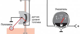
The principle of operation of fuel level sensors is classic and simple - changes in the position of the float are “read” by the control device and transmits the information via a digital or analog signal to visual control devices. The accuracy of the data determines the type and design features of the control equipment.
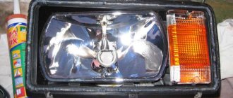
We recommend: Which is better, electric corrector or hydrocorrector for headlights on a VAZ 2110: pros and cons
Lever type
The interaction of sensor elements of this type is presented as follows:
- the float constantly occupies the upper fuel level;
- a potentiometer connected to the car’s electrical network through an indicator on the dashboard, when the gas tank is completely filled, creates a resistance of about 7 Ohms, which corresponds to the “P” mark on the control device;
- when the engine is running, gasoline is consumed, reducing the amount of fuel in the tank - the float drops along with the drop in level, moving the potentiometer slider;
- the movement of the latter along the resistive plates smoothly increases the resistance to 230 - 340 Ohms (depending on the characteristics of the car), where the maximum value informs about a completely empty tank.
The reliability of this design has been proven over years of use. At the same time, the accuracy of the readings deteriorates over time due to wear of the resistive plates and the slider.
Tubular type
The operation of a tubular type sensor uses a control principle similar to the acquisition of information by lever systems, but there are fundamental design differences. Its main elements are presented:
- Housing with guide post and resistive wire.
- Float equipped with slip rings.
- Device mounting flange with a contact group for connecting control wires.
Fuel level control is carried out in the following order:
- fuel enters through a hole in the lower part of the body;
- as the tank fills, the float mechanism moves and will remain at the top point;
- its movement changes the resistance and, therefore, the tank fullness indicator on the indicator;
- at the top point, a small section of the contact wire is involved, and the resistance has a minimum value, at the bottom - the length increases, with a corresponding increase in the final indicators.
Placing the float in a limited space that smoothes out vehicle vibrations provides information about the fuel level more accurately than lever-type units. But the possibility of installation on cars is limited by the design features of fuel tanks.
Electronic (contactless)
Electronic fuel level sensors are installed in the tank when using modern types of ethanol-based, methanol-based gasoline or biodiesel, since the installation of contact units for level determination is not effective - the readings are inaccurate, and the wear of parts is high. In turn, the inactive magnetic fluid position sensor copes with the task successfully and has the following features:
- The executive part is located in a sealed housing; only the magnetic float and lever come into contact with the fuel.
- Fuel height measurements are carried out by a signal generated by a magnetic field.
- Changes are recorded by predetermined segments, the passage of which changes the amplitude of the feedback signal. So, when filling the tank “to full”, the sensor will change readings only after passing the next mark, and the driver will not be able to observe the smooth drop in level.
Important! If you can choose a sensor to install to replace a damaged one, it is preferable to choose a model with digital information transmission - its data has less error than analog devices.
In order not to be left without fuel in the middle of the journey, you need to know the amount of fuel in the tank. Thanks to the device, you can understand whether or not you need to visit a gas station, how much gasoline is in the tank, and whether you can continue driving. This is not just a useful device, but a device responsible for the level of safety on the road. Modern legislation requires the presence of such a sensor and its good condition.
What does the fuel level sensor consist of and how does it work?
The fuel level sensor can work properly for a long time. The mechanism itself is not one of the most painful areas of the VAZ-2114, but, like all other devices, sooner or later it fails. Its breakdown is most often due to the fact that the FLS is in unfavorable conditions.
The device body is quite fragile, which often leads to the sensor breaking due to mechanical damage. Among other things, constant temperature changes significantly reduce its service life. The fuel sensor of the VAZ-2114 is especially painful during the frosty season.
The main purpose of the fuel level sensor is to determine the fuel level in the gas tank and transmit the received data to the indicator, which informs the driver.
In a VAZ-2114 car you can most often find a sensor of the BM-150 type. Regardless of the design feature, the operation of each fuel controller is based on a measuring float made of lightweight material. The operating principle of the device is as follows: a unique signal corresponds to a certain amount of gasoline in the tank. The design also includes a lever and a resistor element.
Taken together, all the parts of the device make it possible to measure resistance, which has different indicators depending on the level of gasoline. Using a sliding contact, it is possible to turn on and off a special indicator on the dashboard.
A full tank has a resistance of 20 ohms, an empty tank has a resistance of 300 ohms.
Types of FLS by connection interfaces
Based on the output signal, the following devices for measuring fuel level are distinguished:
- analog. Data on the amount of fuel is transmitted in the format of the output signal voltage. For example, the more fuel, the higher the voltage. To convert this value into units of volume, calibration is used. For example, a voltage of 2 V corresponds to 10 liters of gasoline. The advantage of such a device is the ability to use it in tandem with the simplest, affordable trackers. However, the analog sensor has a fairly high error - about 4%, so it is not suitable for high-precision measurements;
- digital. An electronic board is integrated into the design of the device, which analyzes the data of the measuring element. Data is transmitted in the format of conventional numbers; using calibration, they are converted into volume units. The cost of a digital fuel level sensor is higher than an analog one. However, such a device is characterized by high accuracy of readings, so it can become an effective element of a monitoring system. In addition, it uses independent power supply, which prevents operational failures due to battery or generator failure;
- frequency – transmits data in pulse frequency format. For example, the higher the fuel level, the higher the pulse frequency. Using calibration, data is converted into volume units. For example, a frequency of 2000 Hertz corresponds to 30 liters. Frequency fuel level sensors are a kind of intermediate link between analog and digital models. They are distinguished by higher accuracy and noise immunity compared to analog ones, but are inferior to a digital sensor in these parameters. Today, frequency fuel level measuring devices are quite rare, but such a sensor can be installed if it is impossible to use equipment with other interfaces.
Common FLS malfunctions
Often, the driver can observe the following situation: while driving on a flat road, the instrument panel displays information about a full tank, and after driving off-road, about an empty one. The readings jump, which is clear evidence of a malfunction of the VAZ-2114 FLS. This disease often manifests itself due to wear on the contact tracks.
In some cases, the situation can be corrected quite easily - bend the slider so that it is located above the worn-out place in the diagram. But such a solution to the problem is not always appropriate. Sometimes you have to replace the entire regulator.
Other malfunctions of the mechanism include:
- The pointer is at zero - most likely the problem is related to the limited travel of the float.
- The low fuel light does not light up - there may be a problem with the potentiometer.
- When starting the engine, the indicator does not light up - there is a problem with the electronics.
- Incorrectness of the data displayed on the instrument panel - you should check the tightness of the float.
If such symptoms of a device malfunction appear, experts also recommend checking all the wires securing the nut sensor. The fastening elements clamp the mass, so if they are not tightened well, the contact will appear and disappear. If the sensor does not show the fuel level of the VAZ-2114, then the contacts need to be cleaned, and if this cannot be done, then they can be completely replaced.
What to do
First you need to carry out diagnostics, that is, find out which part is damaged - the sensor, wiring or the indicator itself. For this, a regular multimeter is used, but you can replace it with a test lamp.
First you need to gain access to the fuel section and the fuel level sensor itself. To do this, with the car running, you need to remove the connector in the service hatch under the rear sofa of the car. Then, using the electrical supply diagram, you need to determine which wire goes from the sensor to the fuel indicator. One connector of the multimeter must be connected to the ground of the car, the other to the positive terminal of the wire coming out of the hole. The multimeter should show the on-board voltage (12 V). If you close the positive terminal to vehicle ground, the indicator arrow should show a full tank. If this does not happen, the wiring or the indicator itself is to blame. If the needle shoots up to the extreme position, the problem is in the fuel sensor.
Modern fuel sensors are best replaced as an assembly. Their price is not so high as to make repairs that do little to help the business. However, in some cases, you can try to clean the sensor from dirt and try to adjust the slider. To do this, you will have to remove the sensor (you must first drain the fuel, turn off the car and remove the negative terminal from the battery). After removing the sensor, you need to inspect the working surface of the sectors for wear. If the width of the wear line is small, you can adjust the slider so that it moves along the undamaged surface of the sectors.
If incorrect readings of the fuel level indicator are not associated with the fuel sensor, then you will have to remove the indicator from the dashboard. Wiring problems can also be diagnosed using a multimeter. The malfunction of the device itself is determined manually after removing the device - if the arrow is jammed, you can try to clean it and adjust it.
Replacing the FLS on a VAZ-2114
Even a novice driver can repair the sensor with his own hands. Of course, the breakdown should not be serious, then replacing the failed element will not be difficult and will not take much time. For example, if a float breaks, you can always purchase a new copy on the automobile market. The old float is easily removed from the holder and a new one is installed in its place.
Oxidized wires are also often replaced with new ones if stripping them is impossible. The price of a new sensor is relatively low, so most often drivers prefer to simply purchase a new mechanism.
The process of replacing the FLS on a VAZ-2114 includes the following procedure:
- Remove the lower part of the rear seat and remove the upholstery, since the sensor is a structural part of the fuel pump. It is impossible to get to the mechanism without going through the module.
- Using a key number 7, release the two screws securing the gas tank cap.
- Then you need to unscrew eight more screws securing the edge of the lid.
- After these steps, the cover can be easily moved forward.
When access to the fuel pump is ensured, it is necessary to remove part of the wire block. Don't forget to unscrew the line nuts. Before the cap is completely released, it must be turned once, this way the pressure in the system will be reduced.
Temperature and fuel gauge glitches
The VDO instrument panel does not work. Temperature and fuel levels are “buggy”
Incorrect temperature and fuel readings? Probably many owners of VAZ 2110 - 2115 have already encountered the problem of incorrect display of fuel and temperature indicator on the dashboards of VDO, “ScheAvtopribor”, Vladimir. For example: The actual engine temperature is 90 degrees (we know this for sure), but on the instrument panel it shows 110 degrees. There are 10 liters of gasoline in the tank, but the instrument panel shows either 20 liters, then 15 liters, and sometimes correctly 10 liters. Moreover, usually the tachometer and speed always show the correct values. I had this problem for about a whole year. When I test the instrument panel (Press the daily mileage button - hold it down, turn on the ignition, all instrument indicator arrows deviate over the entire scale span and the LCD segments are completely filled, and the emergency fuel level warning lamp lights up. When testing the instrument panel, the temperature indicator should smoothly go a distance from 50 degrees to 130 degrees. The fuel level should smoothly go a distance from 0 to 1). If the pointers work correctly during the test, then the problem is electronics. Car service centers say that these instrument panels cannot be repaired. Just buy a new one of the same instrument panel and everything will be fine. It was a pity to spend money on a new VDO instrument panel (about 2,400 rubles), since the engine speed and speed of the car were shown, the temperature was monitored on the STATE 510 trip computer, and when refueling I had to set the gasoline in the same way on the standard computer. It was read theoretically from the controller. By the way, the calculation was quite accurate, but it was annoying to constantly put out gasoline. By the way, here is another main feature that confused me, the fact is that the temperature gauge began to jump strongly when the car’s lights, low beam, etc. were turned on. Recently I decided to tackle this problem and fully understand it. I didn’t really believe that it was an electronics failure. The solution turned out to be very simple. In fact, it was just necessary to bring a good “ground” to the instrument panel. Or just restore the default one. After all the ground connections, the instrument panel began to work correctly. The temperature and fuel gauges now work accurately, even with the lights, heaters, etc. on... All the “grounds” that need to be checked are described below: A fragment of the article was taken from the site www.chiptuner.ru The first connection to the vehicle’s ground is located inside the instrument panel, Top left relative to the relay and fuse mounting block, under the sound insulation. On cars of the first years of production, the ground wires to the welded stud were approached on top of the sound insulation, and then someone’s bright mind came up with the idea of hiding the wires under it. So access to the stud is very inconvenient and is only possible using a tube wrench or an extended 10-mm socket. If there is insufficient connection in this place, when you turn on the headlights or electric window motors, the windshield wiper and washer may turn on, and the central door locking system may work. The second connection is located on a welded stud, on the center console of the instrument panel, on the left side, above the left console screen, under the M6 nut. But even if this nut is tightened properly, and the problem remains, then we move on to the most important point of mass for the entire instrument panel, grounding the entire metal frame of the panel. This is a welded stud with M6 thread. It is located on the lower, inner (cabin) side of the engine shield, in the middle. The nut screwed onto this stud also secures the bracket that secures the front part of the left screen of the console, which some diagnosticians and electricians mercilessly remove due to the fact that there are frequent cases of damage to the ECM harness or central locking system on this bracket. As a rule, the nut is tightened very, very mediocre. If there is insufficient contact in this and the previous connection, when the side lights, headlights and radiator fan electric motor are turned on, deviations of the temperature and fuel level indicator may occur.
Causes of problems
The functioning of the device is disrupted for the following reasons:
- There is no normal contact in any part of the circuit (wires have broken off, areas where connectors are connected are oxidized, solder joints are cracked).
- The indicator on the instrument panel is faulty.
- The float has become detached from the sliding contact.
- The fuse has blown.
- There is no contact between the resistive track and the sliding contact. This happens if oxides appear on the sensor, the contact pressure on the resistive layer weakens, and the tracks wear out.
Possible malfunctions and ways to eliminate them
Sensor readings jump
The cause of this problem lies in the erased tracks on the sensor rheostat board. They wear out under the influence of the runner. Sometimes bending the runner helps for a while; it becomes slightly higher than the worn parts of the tracks. If the abrasions are too great, then replacement is recommended.
The controller gives incorrect readings of the gasoline level
If the arrow on the dashboard of your VAZ 2112 car shows an incorrect level of gasoline, there are many reasons for such an ailment, as well as a number of ways to resolve them. If the fuel level readings are constantly lying (they either underestimate or overestimate the values), then adjusting the fuel controller will help you.
Adjusting the fuel level on the dashboard
So:
- Turn off the ignition and disassemble the dashboard.
- Remove the arrow indicating the gasoline level from the pin and connect all the wires to the instrument connection.
- We unscrew the fuel pump and take it out along with the sensor.
- Turn on the ignition and wait about ten minutes.
- Then we move the sensor spoke to the extreme position that would correspond to a full tank.
- We set the pointer arrow so that it points exactly to the “1” mark and fix it.
- We move the float spoke from the initial extreme position to the other.
- The arrow readings on the instrument panel should also change from zero (corresponding to an empty tank) to o (corresponding to a full tank).
- The indicator arrow shows the wrong amount of gasoline, then we slightly bend the right or left adjusting tabs so that the spoke can move beyond its left or right extreme location.
If the indicator arrow on the instrument panel shows that the tank is empty, but in fact the tank is half full
So:
- You need to check the contacts located on the back of the instrument panel itself.
- We remove the instrument panel, tighten the small nuts on its back side, which are screwed to the indicators, to create contact.
- We check all ground wires, especially the one located under the handbrake.
- If the instrument panel itself is faulty, then it is quite possible to repair it, provided that the panel is of an old model.
- If the arrow indicating the fuel level is off, press the daily mileage indicator button and turn on the ignition.
- Perhaps the float in the car's gas tank is jammed.
- The fuel level sensor (controller) itself may be faulty.
Why does the sensor give incorrect readings?
The fuel level sensor of a VAZ 2114 car may not work correctly, giving false readings, for the following reasons:
- There is additional resistance in the circuit - the connectors have oxidized, deposits have appeared on the resistive layer and the sliding contact.
- The float casting was deformed, causing the float to fill with fuel. This cause of malfunction occurs infrequently.
- A coating has formed on the guide, making it difficult to move the float.
The fuel gauge indicator always shows that the tank is completely full if the float has come off the sliding contact. In addition, such a malfunction may be due to the fact that the wire that goes to the instrument panel has a short, causing the resistance in the circuit to decrease.
How does the device work?
To understand the problem yourself, you need to understand how the fuel level is measured and information is transmitted to the device indicator. The circuit implemented in most vehicles includes the following main elements:
a float made of lightweight polymer is immersed in the gas tank and is often combined with the pump block; gasoline sensor – lever-type potentiometer (otherwise known as rheostat); pointer arrow with scale; connecting wires.
In many modern cars, an electronic control unit is connected to the system.
The classic rheostat is an open coil of high resistance wire. A lever equipped with a contact and attached to the float rises or falls with the level of fuel in the tank, and the contact moves along the turns of the winding. The classic scheme works simply:
- The rheostat and the pointer device are connected in series in the circuit, both are powered from the vehicle's on-board network.
- When moving the float with the lever, the resistance of the potentiometer changes.
- A change in resistance causes an increase or decrease in the current in the circuit, to which the indicator arrow reacts. The scale is graduated according to the resistance values corresponding to the filling of the gas tank.
Self-replacement
To replace the fuel level sensor you will need:
- new device;
- resistance meter;
- screwdrivers;
- open-end spanners.
Remember that the fuel level sensor on the VAZ 2114 is located near the fuel, which means you need to follow safety precautions. First turn off the battery. It is not necessary to completely dismantle it; you just need to disconnect the negative wire. Make sure the tank is no more than 45 percent full. This will greatly simplify the replacement procedure.
Procedure
The broken device is located directly in the fuel tank. Follow this algorithm:
- The device is located in the module together with the fuel pump. Therefore, it is impossible to pull out the sensor alone without hitting the module.
- To access the module, remove the lower cushion on the rear seats and move the trunk lining.
- Using a seven key, unscrew the fasteners that hold the fuel tank cap.
- You will see 8 screws pressing the edges of the cork. Unscrew them.
- Slightly move the tank cap to the front.
- Disconnect the electrical connectors from the pump using a size 17 wrench. Unscrew the nut of the fuel supply hose from the fitting.
- Take your time, be careful. Make 1 preliminary revolution. This will make it possible to reduce the pressure accumulated under the lid.
- According to the diameter of the plug you will find 8 nuts. Unscrew them.
- When dismantling the pump, lift it, turn it clockwise and tilt it. This minimizes the chance of damage to the measuring float.
- Using a flathead screwdriver, move the ring stopper on the module.
- Remove the module cover.
- Remove the end of the connected wire from the terminal of the device responsible for regulating the pressure.
- Release the clamps of the meter and slide it along the holes in the housing.
- Remove the sensor.
Now you only need to replace the removed meter with a new one and repeat all the above procedures in reverse order.
How to replace the FLS on Lanos - step-by-step description
Having understood the question of what fuel level sensors are available, how they work, and what types of devices are installed on Lanos cars, you can begin to replace them. It should be immediately noted that if the tracks are slightly worn, they can be cleaned. However, if the tracks are erased and worn, the sensor must be replaced. To replace it, you will need to first remove the fuel pump module. A detailed description of the process of dismantling the fuel pump module on Lanos is presented in this material.
As soon as the fuel pump module is removed, we begin the procedure for replacing the FLS. To do this, the following actions are carried out:
- First you need to disconnect the power supply of the FLS and low fuel level sensor
- In order to replace the FLS, you do not need to disassemble the plastic flask, inside of which there is an electric fuel pump with a mesh. However, the mesh must be changed regularly, and if it has not been changed for a long time, then it should be replaced
- Disconnect the power supply from the FLS
- Next, the low fuel level sensor, which is located next to the FLS, is dismantled. This sensor is removed along with the plastic bracket. To remove it, you need to press on it from the right and then pull it down.
- Now the fuel level sensor is dismantled, for which you also need to press it to the right and remove it from the groove
- To remove the contacts from the chip, you need to use a thin slotted screwdriver or an awl. Initially, the plastic blocker is removed. To do this, remove the retainer using pliers.
- Now the contacts of the white and blue wires are removed, for which you need to press them with an awl or the tip of a screwdriver from the end side of the chip
- When removing contacts, you must remember their location in the chip
- Remove the wires along with the sensor, and then compare the elements. They must be completely the same
- Install the contacts of the new sensor into the corresponding holes of the plastic chip, and then put the new level and low fuel quantity sensor in place
This completes the FLS replacement procedure. All that remains is to connect the chip and install the module in place. If the level sensor and the reduced fuel quantity are changed at the same time, then the devices are supplied with a chip.
To replace both sensors, you will need to disassemble the plastic flask to eliminate the need to separately remove the contacts.
The fuel level sensor for TA type fuel pump modules is replaced in the same way. The most important thing when carrying out work is to choose a suitable fuel level sensor.
Checking the device with an ohmmeter
It is not always necessary to immediately replace the sensor with a new one. It happens that the problem lies in a completely different component of the car, for example, an injector. Also, if the meter is faulty, it may be possible to repair it. Before replacing, check the sensor:
- To test the device, connect a resistance meter to its terminals. This indicator must be measured when the lever and float are in extreme positions or in the middle.
- In the lower position, meaning zero fuel level, the resistance should be 285–385 Ohms.
- In the central position, which means the tank is half full, the ohmmeter should show 100-135 ohms.
- The highest position is a 100 percent filled tank. The ohmmeter should read 7–25 ohms.
If in at least one position the readings obtained diverge from normal, repair or replace the sensor. After installing the new meter, make sure that the installation arrow on the module cover is directed towards the trunk. Otherwise, you will need to dismantle the system again and repeat the replacement.
Mass air flow sensor
The power unit of the "tens" is controlled using the ECM - an electronic system. This system must always know how much air needs to be supplied for a certain volume of gasoline. These two parameters are closely related to each other, since with their help a combustible mixture with the required density is formed in the engine power unit. After the system determines the required volume of air, it begins to select the appropriate amount of gasoline. As for the regulator, it is responsible for the suction volumes.
Air controller for "ten"
This controller has certain disadvantages, in particular:
- its performance may be impaired if the controller is exposed to moisture;
- if the car is moving at lower speeds, the controller can produce higher readings;
- as practice shows, at idle the air regulator does not work entirely correctly;
- when starting the power unit, certain difficulties may arise;
- the power unit may stop abruptly for no reason after an increased power mode;
- Gasoline consumption during vehicle operation may increase.
We've dealt with the shortcomings, now let's talk about how the device functions:
- The controller design consists of several sensitive elements installed directly in the line itself through which the air flow passes. One of these components is designed to fix the temperature of the air flow, and the other two are always heated to the required parameters.
- To correctly determine the air flow rate, the principle of measuring electrical power is used to maintain the desired temperature level.
- The air regulator controller has a special mesh installed in the line, designed to filter the air flow.
- Thanks to this, the sensor can transmit the necessary data to other regulators designed to activate certain modes. Subsequently, these regulators either change or support the loads.
Replacing the fuel level sensor on a VAZ 2113, VAZ 2114, VAZ 2115
Welcome! Fuel level sensor - thanks to it you can always find out how much fuel is left in the tank, on all cars this sensor is located in the gas tank, and it consists of a float, a float rod and a so-called potentiometer (A potentiometer is an electronic part of the sensor, which, depending on depending on how much the float is raised, it changes its resistance), over time the electrical contacts of the potentiometer oxidize, which is why the sensor begins to lie very much or stops working altogether, or in some cases when the tank is deformed (And the tank on front-wheel drive cars is located very low ) the rod at the fuel level sensor is also deformed, due to which the fuel level indicator will begin to lie and incorrectly show the car’s gasoline, and finally, about the float, let’s say that over time it will develop holes due to poor-quality gasoline and a gap will form through it, it can also be formed if the float is touched with something sharp or if it is deformed during installation, due to this gap that can form in the float, the float will simply sink and it will no longer adhere to the surface of the gasoline and therefore, the readings given by the gasoline indicator will be constantly at zero (no gasoline).
Note! To replace this sensor, you will need: A screwdriver, a set of keys and, just in case, stock up on pliers, because they can also come in handy!
Summary:
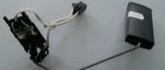
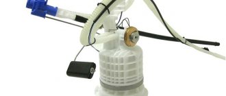
Where is the fuel level sensor located? In old cars (we're talking about classics), the sensor was located directly in the gas tank, but on new injectors, the sensor is also located in the gas tank, but only in this case, it is combined with such a part as the gas pump, so to replace this sensor, first the gas pump you will need to pull it out and only then start replacing it (For information on how to remove this pump, read the article: “Replacing the fuel pump on a car”), in the photo below, by the way, this pump has already been removed and this sensor, which is located on it, is indicated by an arrow.
When do you need to change the fuel level sensor? At the beginning of the article, we already described all the problems that may occur with it, but we did not describe how it can be checked for serviceability (You need to check for serviceability only if the fuel level indicator does not show gasoline at all, but if it shows but with an error, then most likely the rod on your sensor is either bent, or it itself has become unusable and gives much less resistance, which is very unlikely), in the beginning you will, of course, need to remove the fuel pump (read how to remove it below), after removing it, connect block of wires to the pump, if you previously disconnected it, as soon as this is done, turn on the ignition and move the float up and down, while the arrow of the fuel level indicator should also move if you connect another ohmmeter to all this and check what resistance is given by the sensor, then the test will be even more successful, it is connected to the wire terminals in the place where the wire block needs to be inserted, after connecting the device, move the float all the way up and the readings it should give is 7–25 Ohms, then move the float approximately to the middle, the readings that the device should give are 100–135 Ohms, and finally, lower the float to the very bottom, in this case the device should give readings of 285–385 Ohms, if everything is so, then the sensor is working and does not require replacement , for more details on how to check it, see the video below:
Causes
Now you need to find out why this sensor on your car does not display the current fuel level correctly and what is causing this.
There are several potential reasons. Therefore, each of them needs to be considered in detail.
- Violation of the tightness of the installed float. It is found on sensors where the float is made in the form of a ball made of fragile plastic. With mechanical shocks, as well as under the influence of extreme cold, the material is destroyed. If the seal is broken, the float simply remains on the surface of the liquid or sinks. As a result, the controller shows that there is no fuel. For repairs, it is necessary to replace the float separately, or the entire sensor. Much less often, the float part is disconnected from the lever and begins to move independently inside the container.
- Lever damage. Due to its deformation, the float loses mobility or transmits information incorrectly. The cause of the problem is long driving. Moreover, on uneven and bad roads. Or in violation of the rules for dismantling the fuel unit from the tank. You can try to restore the lever. But more often repairs are carried out by replacing it.
- Deformation of the controller body. Because of this, the installed resistive elements give incorrect readings, or the lever is damaged and does not record data correctly. The reason is the filling of low-quality flammable liquid, or mechanical stress.
- Breakage of resistive elements. A common reason why the FLS stops working correctly. It occurs due to natural causes. That is, resistors wear out from a long service life. The contact between the elements disappears, and the arrow ends up at zero, or simply twitches.
- There is no contact on the electrical circuit section. This happens on those contacts that can simply oxidize over time due to exposure to moisture or the fuel itself. Wires are damaged, the integrity of the insulation is compromised, breaks occur, etc. Sometimes the reason lies in the electrical connectors.
- FLS wire shorted to ground. This occurs precisely with the signal wire, which begins to short to ground. As a result, the FLS indicators become incorrect, and the resistance tends to zero. No matter how much fuel is filled, the sensor will show a fictitious full tank.
- Burnt fuse. The car has a sensor that is responsible for the FLS. The specific fuse number should be found in the owner's manual for your specific vehicle.
- Failure of the fastening on the housing inside the fuel tank itself. As a result, the sensor fell into the tank or was distorted. Usually accompanied by the spread of fuel odors into the cabin.
- Break on the signal wire side. Found on tubular sensors. Then the arrow constantly indicates that the fluid tank for operating the internal combustion engine is empty.
- Plaque formation. Another characteristic feature of tubular type controllers. Plaque accumulates on the guide post. This interferes with the normal and free movement of the installed float. The deposit appears due to the filling of low quality fuel. The arrow stops in one static position.
- Damage to the magnetic sensor, wires. Relevant for contactless fuel level monitoring devices. Some FLS models of this type have control and control boards. Problems happen to them too. Then the sensor completely fails, and the correct fuel level is not displayed.
Practice shows that most often problems are observed from the resistive elements, as well as the float. They wear out over time and can no longer display and transmit data correctly.
Don't immediately blame the sensor. There is a possibility that the arrow of the device is broken, or there are faults on the side of the wires connecting the elements.
What is a fuel sensor
Advertisements
This small device is a rheostat with a resistor, which is assembled from nichrome components. The changing part of the rheostat in contact with the liquid moves using a lever with a float.
At the opposite end of the lever there is another contact, which, when in a specific position, closes a circuit that controls the start of production of spare fuel. The reserve balance ranges from 4 to 6.5 liters.
Sadly, this device (see photos at the beginning) is considered one of the elements that often fails. In some cases, replacing the fuel sensor may not be necessary, you just need to perform minor maintenance.
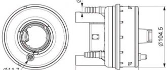
Device
The regulator includes two cavities - fuel and vacuum. Inside the vacuum there is a membrane that reacts to the air pressure coming from the power unit. Inside the fuel cavity there is fuel under high pressure.
The force of fuel pressure is resisted by a valve device. If the pressure is excessively high, the excess is returned back through the relief means.
How the regulator works
The fuel regulator ensures that the difference in influence on the membrane is maintained on both sides, that is, both cavities. Only under such conditions can the engine function normally.
The sensor serves to maintain pressure differences regardless of the current engine speed. Fuel injection will not be possible if the pressure in the manifold is equal to or greater than that in the injectors. Injectors are required to have higher pressures.
If everything works well, the following processes are observed:
- The vacuum in the suction cavity of the manifold is reduced during quiet operation;
- In response to this pressure, the fuel in the rail and its supply to the injectors increases.
The principle of operation of the level sensor on the VAZ-2110
Operating principle of the fuel level sensor.
The vast majority of fuel level sensors in inexpensive cars have a similar design. The operation of the device is based on the principle of measuring the resistance of a simple rheostat.
VAZ fuel pump devices.
The stationary part of the device consists of nichrome contact tracks, and the moving part is a contact that cuts off part of the track, thereby changing the output resistance. As a result, we have a system that converts the sensor resistance into the amount of fuel indicated on the instrument panel. A spoke and a float are attached to the movable contact, which moves depending on the amount of gasoline in the tank.
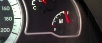
The photo shows the scale of the fuel level sensor.
On the tenth VAZ family, the sensor is mounted in the same block with the fuel pump, fuel module. The sensor is capable of signaling a low fuel level (4–6 l), giving the unwary driver a chance to make it to the gas station.
To replace the fuel level sensor, they try to find original spare parts with article number 21101–3827010, 21102–3827010 or 2112–3827010. The price of a sensor assembled with a spoke and a float ranges from 350 rubles (Tochmash enterprise) to 420 (SEPO, Cartronic, Motorika).
It is better not to purchase spare parts of dubious origin. In any case, the new device must be compared with the old sensor.
Other fuel level sensor options
Potentiometric FLS has a number of limitations in its scope of application. Thus, it cannot be used on cars that use methyl, ethyl alcohol or biodiesel as engine fuel. This is due to the fact that such fuel acts more aggressively on electrical contacts and leads to their premature wear.
As an alternative, various non-contact sensors, such as MAAPS or an inactive magnetic position sensor, are used to measure the amount of fuel in the vehicle tank. The MAAPS sensing element does not come into contact with the fuel.
It has the following operating principle. Such a sensor determines the amount of fuel remaining in the tank using a float connected to a permanent magnet via a lever. The magnet moves along a sector on which a large number of plates of various lengths are deposited with rays. Electrical signals are formed in the plates under the influence of a magnetic field (different in each plate), depending on what signal the sensor gives, the remaining fuel is determined.
When you need to change the DFID sensor 2110: symptoms of sensor malfunction and check
During the operation of a vehicle, the mass air flow sensor 2110 can fail for various reasons, one of which is the long period of use of the device. When a sensor fails, it is usually not repaired; it is simply replaced with a new one. The following symptoms may indicate that the sensor is not working properly:
- “Check Engine” lights up on the car’s dashboard (you need to check the engine);
- fuel consumption increased, acceleration dynamics decreased;
- the car engine does not start;
- at idle, the car’s internal combustion engine operates jerkily (change in idle speed down or up).
All of the listed signs of sensor malfunction indicate that air is not being supplied to the mixture in the volume required. Taking into account the fact that this problem may be associated not only with a malfunction of the mass air flow sensor, before proceeding with dismantling the sensor, it is necessary to make sure that it is faulty.
In fact, the VAZ 2110 mass air flow sensor can be checked for performance using three methods: in motion, with a multimeter, visually. Checking the mass air flow sensor 2110 experimentally (in motion) is the easiest and fastest way. It consists of analyzing the operation of the vehicle’s internal combustion engine when the sensor is forcibly turned off.
Algorithm of actions:
opening the hood, disconnect the mass air flow sensor connector; start the car engine; since the car will operate in emergency mode, the “Check Engine” light will come on and the amount of air in the fuel mixture will be determined depending on the throttle position; Having driven a car operating in emergency mode, you need to pay attention to its dynamics and compare them with the dynamics before the sensor was turned off; If the car accelerates faster with the sensor turned off, the air flow sensor is faulty.
The next stage of diagnosis may be checking the mass air flow sensor 2110 with a multimeter. This method of checking the sensor for functionality involves the use of a measuring device (multimeter).
Before checking, you need to understand the design of the device and find out its “pinout” (soldering of wires on the board). There are four wires coming out of the MAF. Typically these are the wire to the main relay (pink/black or pink), ground (green), power (gray), and signal input (yellow).
To check you need:
- set the multimeter to constant voltage measurement mode, setting the limit to 2 Volts;
- without starting the engine, turn on the ignition;
- connect the black multimeter probe to the ground wire, the red one to the signal input of the multimeter sensor, inserting the multimeter probes through the rubber seal of the connector;
- take measurements and use the results to determine the state of the sensor.
Based on multimeter readings:
- voltage 0.996-1.01 Volts (new sensor);
- voltage 1.01-1.02 Volts (working sensor in good condition);
- voltage 1.02-1.03 Volts (sensor working, with long-term operation);
- voltage 1.03-1.05 Volts (sensor is worn out and may fail);
- voltage from 1.05 Volts and above (the sensor is faulty and requires replacement).
If the device is not at hand, the faulty sensor can often be determined by its appearance, that is, by visual inspection. In this case, it is necessary to dismantle the device and carefully inspect it for mechanical damage or for the presence of liquid in the sensor and air pipe.
The reasons for liquid and dirt getting into the sensor can be different (for example, the oil level in the crankcase is increased, dust gets on the hot-wire anemometer due to untimely replacement of the air filter, the oil sump of the crankcase ventilation system is clogged, etc.).