What to do if there is no light in the house? A current generator can help solve the problem. But if this equipment also fails, checking the generator with a multimeter will help determine the malfunction. Regardless of the type and brand, with the help of this device, once you find out the cause of the malfunction, you can carry out simple repairs yourself.
There are many types of generators, from large and powerful industrial devices to small automotive devices. But the testing algorithm using the tester is the same for any generator.
How to test a generator with a multimeter
What to do if there is no light in the house? A current generator can help solve the problem. But if this equipment also fails, checking the generator with a multimeter will help determine the malfunction. Regardless of the type and brand, with the help of this device, once you find out the cause of the malfunction, you can carry out simple repairs yourself.
There are many types of generators, from large and powerful industrial devices to small automotive devices. But the testing algorithm using the tester is the same for any generator.
Beginning of work
Multimeter device
To start testing, no special preparations are required. You just need to prepare the multimeter itself. It is also advisable to check the generator - inspect the generator stator, diode bridge, voltage regulator, etc. This makes it possible to identify faults at an early stage. In addition, an external inspection of other elements of the vehicle's electrical circuit should be carried out. No further work may be required.
Generator circuit
So, the test includes several stages:
- Inspection of the relay regulator.
- Checking the diode bridge.
- Checking the stator.
- Checking the rotor.
Symptoms of a problem
The generator operates under high mechanical and thermal loads. Its bearings can crumble due to excessive wear or contamination, and the diodes inside the voltage regulator lose their properties over time. The heat from the motor, in addition to heating the windings, creates an additional load. In other words, like any part in a car, the generator does not last forever. Its service life is difficult to predict, since so many factors influence the survivability of the component.
Checking with a multimeter
Rotor check
Using a multimeter in resistance measurement mode, ring the excitation winding (on the rotor). To do this, attach the measuring probes to the slip rings.
The resistance of a serviceable winding should be within 2.3 -5.1 Ohms:
- if there is no resistance at all, then there is a break in the winding;
- if the resistance is lower than expected, then most likely there is an interturn short circuit;
- if higher, then there may be poor contact or the winding leads to the slip rings are not properly soldered.
We also measure the current consumed by the excitation winding.
To do this, we apply +12 volts to the slip rings and connect a DC ammeter to the open circuit. The current consumed by the winding should be within 3-4.5 Amperes. If the current is too high, it means there is interturn ignition in the rotor winding and it requires replacement. The maximum current of the relay regulator is 5 Amps, so if the rotor winding current is too high, the voltage regulator also needs to be replaced.
The insulation resistance can be checked with a high alternating voltage of 220 volts by applying voltage through a 220 V, 40 W incandescent lamp, one contact is connected to the slip ring, the other to the metal rotor housing.
If there are no short circuits to the housing, the lamp should not light. If the lamp filament glows even just a little, then there is a current leak to ground. This winding requires repair or replacement.
Take precautions when working with high voltage!
Compliance with operating rules and high-quality repair of generators is the key to uninterrupted and efficient operation of gasoline and diesel devices. Timely contact with specialists will help you not only eliminate the malfunctions that have arisen, but also prevent equipment failure in the future.
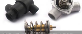
Design and basics of operation
A gasoline generator is a device that runs on liquid fuel. Its task is to convert the mechanical energy of the engine into electrical energy, which is produced by the alternator. These are two main nodes that are interdependent. Repair of gasoline generators is most often associated with the maintenance or replacement of elements that are part of the engine and alternator or are functionally connected to them.
Equipment design
The engine is equipped with a number of systems: starting, shaft speed stabilization, cooling, exhaust and air supply. This unit is driven most often in two ways:
- By hand pull;
- Electric starter.
In more functional models, the engine is started by autostart. If it is quite possible to repair autonomous gas generators of a mechanical starting system yourself, then understanding the automation is much more difficult.
There are single-stroke and four-stroke models of alternators (generators). In gasoline mechanisms, the second of these are most often used.
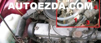
Checking a car generator
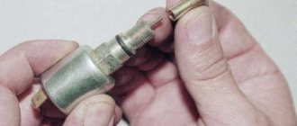
To check the generator in a car at home, you need a measuring device - a tester, which has the functions of measuring voltage and resistance. Nowadays, digital testers are the most common and have the lowest cost (Fig. below).
Digital tester for taking measurements in electrical equipment
Such a device is sufficient to carry out almost any measurements in the electrical equipment of a car. In addition, the devices operate without observing the polarity of connecting the probes.
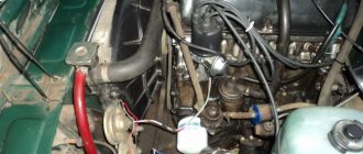
Some measurements are carried out with the engine running.
In this case, the operation of the generator is checked only with the battery connected. Without a battery, the voltage regulator will not function normally, and an overvoltage will be supplied to the vehicle's on-board network, which will most likely lead to failure of the on-board controller and other electronics.
Below we will tell you how to test the generator with a multimeter. First of all, you need to measure the voltage at the battery terminals with a tester while the engine is not running. After the engine is started, the voltage should increase and reach the nominal value, which means the battery is charging. Otherwise, the generator must be dismantled and completely inspected. You can check a car generator without removing it from the car, but this technique varies significantly depending on the brand of car and the generator.
Do-it-yourself generator repair, maintenance and replacement
Good maintenance, which any car requires, will allow it to serve its owner for many years without serious problems. You just need to monitor the serviceability of the main components and systems. These include a converter of mechanical energy into electrical energy. Replacing and repairing car generators is one of the main operations of service center workers.
After all, without power supply, the comfort of the vehicle disappears, and it turns into a horseless cart made of stamped metal. The generator rarely stops functioning immediately. It usually gives the owner signals for quite a long time by “winking” its sensor in red and making noise from under the hood. You must carefully study the operating manual of the machine.
Weak or overcharging of the battery is also a symptom of its suffering. Checking it will show a number significantly less than 13 Amps on the multimeter. Then you need to seek help from specialists. Although, if a car enthusiast feels sufficiently prepared and experienced to try to find and fix the breakdown on his own, then he can begin to master the profession of a car mechanic.
Of course, technologically repairing generators is not difficult, but it is better to stock up on a sufficient set of tools and enlist the support of a friend experienced in this matter. The soldering skills of at least one of your friends will be very useful. Otherwise, you will have to invite a third one. You can start the event. It should be led by the most experienced member of the team.
Preliminary identification of the cause of the breakdown
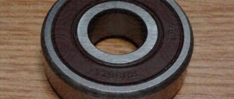
- Noise during operation indicates wear of the bearings. If one bearing breaks, it will make a small sound. If two bearings are involved, the generator will rumble.
- The regulator indicator flashes red and charging is normal. Most likely, the relay in the electrical circuit is broken.
- Insufficient battery charge can be explained by worn-out or broken brushes, diodes, relays, or voltage regulator. Or there is a short circuit in the windings of the unit.
Synchronous alternators
Synchronous generators operate in a similar way, but the shaft speed is maintained at a constant speed. Hence the parameters are more stable. Here are a number of differences that need to be taken into account in order to properly test the generator with a multimeter.
AC winding
The stator (called the armature) often has an alternating current winding that synchronizes the rotation. Its role is difficult to overestimate, and the turns are located, for example, between the windings of the main coil. The role of the poles in this case is synchronizing. A voltage of the required frequency is supplied here, which, through interaction with the inductor (rotor), sets the speed of rotation. Typically the winding dimensions are smaller than the main winding and the resistance is higher.
Subexciter
Large synchronous generators contain auxiliary equipment - a subexciter. This is a synchronous machine whose shaft is equipped with permanent magnets. The voltage generated by the generator is rectified and is subsequently used as current for the exciter. This saves energy. Permanent magnets also reduce the number of current collectors, which has a positive effect on the reliability of the entire system. The subexciter becomes, in fact, a simple synchronous motor; the stator winding is tested by the tester in the usual manner.
Diode bridge
In connection with the above, sometimes it is necessary to check the diode bridge of the generator with a multimeter. By the way, this is relevant for car enthusiasts, where a Larionov circuit is often used to rectify the current. The diode bridge is called depending on the design. In everyday life, the ones shown in the figure are the most common. The first is considered a typical solution for single-phase alternating current, and the second is the Larionov circuit.
According to the given figure we show how to ring. A single-phase diode bridge is safely assessed for the integrity of each diode individually. To do this, the appropriate mode is set on the multimeter, then, regardless of the position of the cathode and anode, the probes are presented on one side, then on the other. As a result, direct connection produces a value of 500 - 700 Ohms, and reverse connection produces a break.
Popular designs of diode bridges
The result is different if the bridge is shorted by resistors somewhere in the circuit, but this rarely happens, and their value is large enough to have no effect. The Larionov automobile bridge is called similarly. If possible, remove it from under the hood. The input of each phase is connected to the positive and negative output. Resistance value – up to 1 kOhm. The reverse connection is easy to check. It is necessary to put the red probe on the plus side and, in turn, make sure that all phases give an infinitely large resistance to the black probe. The mass is checked in the same way. Here the black probe goes along the negative output, and the red one goes through the phases.
Description of the generator armature
Before checking the unit, please review the basic information. The anchor consists of the following elements:
- shaft;
- slip rings;
- brush assembly;
- collector;
- excitation winding;
- core.
The core of the device includes several sheets made of electrical steel, their thickness should be 0.5 mm. The core is mounted in the shaft, but if the diameter of the armature is very large, then in a cylindrical sleeve. As for the collector, it consists of copper plates, the number of which may vary depending on the design. The collector is assembled separately, after which it is pressed into the shaft using an insulating sleeve.
Generator unit armature device
The winding is made in the form of several sections, their ends are mounted in special protrusions on the collector plates. With the help of the latter, the winding sections are connected to each other in a serial manner, forming a closed circuit. Windings can be wave or loop. In the first, the section leads are connected to the collector unit, and they are connected to each other in a wave-like manner. In loop devices, the leads are connected to the collector plates, and they are connected to each other directly on the collector.
Operating principle
The armature of the generator unit rotates as a result of the influence of the bearing shields, as well as the bearings themselves mounted on the shaft. The shield itself, which is located next to the collector, is called the front shield. Behind this shield, on the shaft, there is an impeller designed to cool the device. To ensure air flow and also remove heat, the shields have special openings that are closed using protective covers with meshes. There are also holes in the front shield, but they are necessary for servicing the component elements of the device.
The armature of the device is connected to the network via a brush assembly. The elements themselves are located on special holders, which are fixed on the so-called fingers. These fingers are located on the traverse, which, in turn, is fixed on the front shield or frame, depending on the design. The pressure of the brush elements can be adjusted; special springs are provided for this.
The number of so-called brush fingers corresponds to the number of poles, and one half of them should have a positive polarity, and the other half should have a negative one. In general, the brush assembly divides the winding into several parallel branches; their number can also vary depending on the type of winding (video author - Volodymyr Zagryvyi / Vladimir Zagryvyi).
The on-board network of the vehicle is connected to the generator unit through a special terminal box, where there is a board with terminal marks on the windings. To ensure lifting or moving the generator unit, there is a corresponding bolt on the top of the frame. On its body there is a plate indicating the manufacturer, as well as basic technical data about the device. One of the main disadvantages of the generator device is the rather large complexity, as well as the too weak strength of the brush assembly, as a result of which the device requires periodic diagnostics and maintenance.
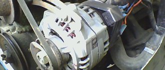
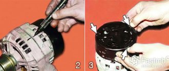
Checking the generator rotor VAZ 2108, 2109, 21099
A malfunction of the generator rotor of VAZ 2108, 2109, 21099 (37.3701) cars primarily leads to the disappearance of the charging current and discharge of the battery.
On the instrument panel after starting the engine, the battery discharge light will be constantly on, indicating that there is no charging current. The voltmeter needle is in the red zone or on the border with it. If you check with a voltmeter (multimeter, tester, etc.) the voltage at the battery terminals with the engine running, it will be lower than the required 13.6 V.
Malfunctions of the generator rotor can be a short circuit in its windings and separation of the excitation winding leads from the slip rings - a “break”.
Tools needed to check the rotor
Multimeter, tester, voltmeter, etc.
If they are not there, then the control lamp is a 1-5 W, 12 V light bulb with wires soldered to it .
Repair and restoration
Most generators consist of a rotor and two aluminum shells with stator windings sandwiched between them. Both body parts are connected using bolts. The brushes and straightener assembly are located on the back. Restoration involves the following types of work:
- disassembly;
- testing of windings and rectifier;
- replacing the regulator;
- installation of new brushes;
- replacing the front and rear bearings;
- restoration of stator windings;
- rotor replacement and balancing.
- testing.
Do-it-yourself dismantling of the assembly is a fairly simple procedure for most cars. As a replacement, you can purchase a new unit or buy a refurbished one from companies specializing in the repair of auto generators. The worst option is to take the unit from disassembly, since in this case the chances of long-term operation after replacement are low. To remove the generator, the following steps are most often required:
- Turn off the car and disconnect the battery terminals.
- Provide access to the unit and connectors on it.
- Remove the terminal covers and loosen the bolts.
- Disconnect the terminals and remember their original location.
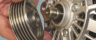
- Loosen the pulley.
- Remove the alternator belt.
- Remove the bolt on the armature shaft.
- Unscrew the mounting bolts and remove the generator.
To install a new or repaired unit, you must perform the steps in reverse order. These instructions are very general, since the design and location of the generator unit can vary greatly among different car models. Often the drive is equipped with automatic tensioners or V-belt drives, and attachments significantly complicate access to the unit and require a unique disassembly algorithm. In any case, during such work it is useful to replace the belt.
The simplicity of the procedure for installing and dismantling the generator, as well as the availability of belts for it, implies a low cost of such work at specialized stations. Therefore, if you have doubts about your own strengths and skills, it makes sense to turn to specialists.