All modern cars are equipped with hazard warning lights, which cannot be said about older cars. For example, in this article we will talk about the legendary Russian “Kopeyka” - VAZ 2101. Since these cars are not equipped with a warning light, car owners have to install it themselves. What is the wiring diagram for the emergency lights on the VAZ 2101 and how to correctly carry out this task - read on.
Purpose and functions of the alarm system
The emergency warning light on the VAZ 2101 is used to notify other road users that the vehicle has made a forced stop due to a malfunction. In accordance with the rules of the road, if a car breaks down, in some cases the driver is obliged not only to turn on the emergency lights, but also to display the appropriate sign. Moreover, it must be placed at a certain distance from the car - this issue is regulated by traffic rules.
Emergency button on a penny
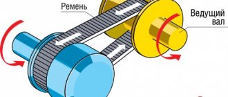
Replacing the turn relay VAZ 2114
Now it’s time to talk about how to change the turn relay on a VAZ 2114. To carry out all the work you will need: - patience and free hands.
Replacement instructions:
- The first stage is the simplest - open the hood of the car.
- At the second stage, you need to find the mounting block in which the desired product and fuses are located. Let us remember that the location of the MB is located directly above the right (driver's shock absorber strut).
- To access the contents of the block, we will need to open its plastic protective cover. This can be done by unlatching the two side latches.
- Now you can observe the entire internal structure of the box, however, we are only interested in the product marked K2. Keep in mind that pulling the part out by hand is quite problematic and inconvenient. Especially for such purposes, you can find specialized plastic tweezers in the block, with the help of which it is very convenient to pull out the part and fuses, which we will certainly use.
- To reinstall, take a new product and insert it into the seat so that the three metal contacts are inserted into the socket. After this, press the body of the device and fix it firmly. This completes the replacement of the VAZ 2114 turn signal relay.
Turn signals play an important role in road safety, and their failure can lead to a lot of trouble. A small device - a turn relay - is responsible for the operation of the turn signals. Read about what types of turn relays are used in VAZ cars, how they are designed and work, as well as about their malfunctions and repairs in this article.
Installation and configuration instructions
Installing emergency lights on a VAZ 2101 is not a particularly difficult task; almost anyone can cope with it. To properly connect the emergency lights to a VAZ 2101 with your own hands, you need to prepare everything you may need to complete the task.
Set of tools and materials
So, what you need to prepare before starting the process:
- Locksmith tools, including wrenches, screwdrivers, pliers, etc.
- Insulating tape.
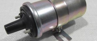
- Four-contact light signal relay from the “Six”.
- Six-pin button for activation.
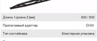
- Five meters of installation wire (video by Alex Gordon).
Work execution algorithm
So, let's start the process:
- First you need to remove the center console. To do this, you need to unscrew the bolts that secure the trim to the steering column. You will also need to remove the side trims of the windshield pillars.
- Having done this, you can remove the instrument cluster. Be careful not to damage the device.
- Next, disconnect the wires from the light bulb that illuminates the glove compartment. Then unscrew the bolts that secure the sides of the glove compartment to the control panel, as well as the bolts that secure its lower part. After unscrewing all the screws, the glove compartment itself can be removed.
- Now you need to remove the screws that secure the bottom of the dash to the front cross member. Then the nuts of the upper fastening are unscrewed; it is best to reach them through the technological opening of the glove compartment.
- After completing these steps, you can remove the handles from the stove control panel. To do this, at the junction of the lever with the handle, use a screwdriver to bend the lower part of the upper handle, and at the lower handle, you need to bend the upper part.
- Next, you need to disconnect the connectors with wires from the control panel backlight switches, side lights, and also the stove. Then, using a wrench, you need to unscrew two more bolts that secure the fastenings of the stove control levers. After completing these steps, you will be able to dismantle the control panel.
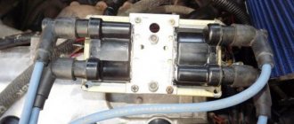
- Now let's move on to installing and connecting the main elements. First, decide on the location of installation of the system power button. It should be installed on the center console so that the driver can reach it as quickly as possible if necessary. It’s still too early to install the button, but you need to decide on the installation location now, since this will determine how much wire you need. Now remove the old turn signal relay from the car and disconnect the three cables from it - usually they are colored black, gray-white and orange.
- Next, take a new six-wheel relay. The second contact of the relay must be connected to the wire that was removed from contact L on the turn signal relay, as well as to output 7 of the button.
- The first contact of the relay must be connected to the fourth contact on the button itself. The third contact is connected to the cable disconnected from contact P on the turn signal relay. Then you need to connect the cable from the fourth contact to ground, that is, the body of the vehicle - it is best to connect it to the relay fixing nut.
- The next step is to connect the button itself. The fourth contact of the button should be connected to the first contact of the relay used. Its second contact must be connected to the cable that was disconnected from the positive contact of the rotary relay. The seventh contact is connected to the second contact of the relay, and the first and third contacts are connected to the steering column turn signal switch; in this case, the order of connection does not matter.
- Now all you have to do is connect the eighth pin to any positive cable; alternatively, you can wedge it into the electrical circuit from the cigarette lighter. If you decide to connect the plus directly to the battery or generator unit, the circuit will need to be protected with a fuse.
- At this point, the installation procedure can be considered complete. All you have to do is securely fix the wiring to prevent chafing of the cables. Reinstall all previously removed interior trim elements, center console, glove compartment, etc.
Materials:
1. Electrical tape (preferably blue, as it is especially durable) 2. Four-pin turn signal relay from VAZ 2106 3. Relay connector 4. Six-pin alarm switch off button 5. Connector for the button 6. Wire for mounting and connecting the above. Tools: 1. Pliers with wire cutters 2. Flat-head screwdrivers 3. Phillips screwdrivers 4. Open-end wrench 10 5. Knife For those who want to save money at the expense of manufacturability: you can use the original relay from the VAZ 2101, but in this case it will work adequately not guaranteed as this relay is very sensitive to load changes. For this reason, the following installation method involves replacing the relay with a more modern one. Let's get started, unscrew the nut securing the turn signal relay and disconnect three multi-colored wires from it. Next, we determine where to install the hazard warning button. Here we give freedom to our imagination, but a lot also depends on what kind of panel is installed in your car. To the second contact of the relay we connect the wire removed from the contact of the old relay, marked with the letter “L”, and connect all this to the seventh contact of the alarm button. We connect the first contact of the emergency light relay to the fourth contact of the button. We connect the third contact of the relay with the wire removed from the “P” contact of the old relay. We attach the wire coming from the fourth contact of the relay to the car body. The optimal solution would be to secure the wire under the fastening nut of our relay.
Scheme of emergency lights (hazard warning lights) for VAZ 2101 cars
Thanks for subscribing!
Now tighten the relay mounting nut with moderate force so as not to break the plastic mount. Then we connect the second contact of the button to the positive wire of the old relay. We connect the first and third contacts of the button to the steering column turn signal switches in any order. The eighth contact of the button is connected to a constant “plus” (independent of the position of the key in the ignition switch). It is advisable to protect this circuit with a fuse. The most suitable would be to install a fuse rated 8A. Next, you should wrap the wires with electrical tape and secure them so that they do not dangle, and install all the previously removed casings and panels. Now we have a full-fledged alarm system and can live a new, full life. The entire procedure for installing an alarm system on a VAZ 2101 takes 2-3 hours.
Video “Visual instructions for installing emergency lights”
What nuances should be taken into account when laying wires and installing a button to activate the emergency lights - see the video below (author - LESHA MASTER).
At first I wrote this instruction only in my logbook, but seeing its popularity and the fact that people use it and everything works out for them, I decided to post it here. This is my first article for a wide range of people, please do not judge strictly.
As you know, the emergency warning system began to be installed on cars of the VAZ family starting from the 2104 model, accordingly, it was never on my dime, but the need for this device was obvious: it means flashing an emergency light to the person who let you pass in a traffic jam, and winking at a pretty girl , or simply, almost legally, stop at a public transport stop in front of the bus and run to the kiosk, almost without violating traffic rules, and I’m generally silent about the forced technical stop...
So, for installation we need:
— turn signal and hazard warning relay from VAZ 2106 (four contacts)
- mother block for connecting the relay (2 unnecessary contacts need to be removed).
- hazard warning button from VAZ 2106 (six contacts)
— connector for connecting a button
- wires about 5m of different colors
- electrical tape or heat shrink tubing.
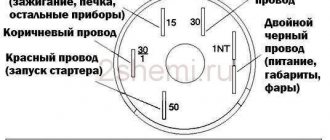
The turn signal breaker circuit for the VAZ 2101 and their modifications is as follows:
1.Front direction indicators 2.Repeaters of direction indicators on the front fenders. 3.Battery 4.Generator. 5. Ignition switch. 6. Fuse block. 7. Relay turn signal breaker. 8.Indicator lamp in the instrument cluster. 9. Steering column turn signal switch. 10. Direction indicators in the rear lights.
Electrical diagram of the rear wiring harness Kalina 2
1, 2 – rear wiring harness blocks to the instrument panel wiring harness blocks; 3 – right side direction indicator; 4 – left side direction indicator; 5 – hand brake sensor; 6 – rear wiring harness block to the tailgate wiring harness contacts; 7 – interior lighting unit; 8 – switch in the driver’s seat belt; 9 – trunk lighting; 10 – electric fuel pump module; 11 – right lamp; 12 – rear wiring harness block to the tailgate wiring harness contacts; 13 – left lamp; 14 – rear wiring harness block to rear left door wiring harness block; 15 – rear wiring harness block to rear right door wiring harness block; 16 – rear wiring harness block to the front right door wiring harness block; 17 – rear wiring harness block to the front left door wiring harness block; 18 – airbag control unit; 19 – rear wiring harness block to the front wiring harness block; 20 – block of the rear wiring harness to the block of the wiring harness of the parking system sensors; 21 – control unit and alarm unit of the safe parking system; 22 – parking system switch; 23 – speaker of the safe parking system; 24 – switch for interior lighting in the driver's door pillar; 25 – interior light switch in the right front door pillar; 26 – switch for the interior lighting in the pillar of the right rear door; 27 – interior light switch in the left rear door pillar; 28 – right seat electric heater switch; 29 – left seat electric heater switch; 30 – electric heater of the right seat; 31 – electric heater of the left seat; 32 – driver’s seat belt pretensioner; 33 – passenger seat belt pretensioner; 34 – central unit of body electronics; 35 – sensor for automatic glass cleaning system (rain sensor); 36 – rain sensor sensitivity regulator; 37 – rear wiring harness block to the instrument panel wiring harness block; 38 – right rear speed sensor; 39 – left rear speed sensor.
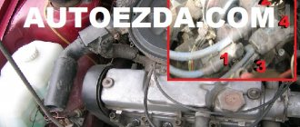
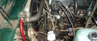
Lower left part of the VAZ-2106 wiring diagram
This part of the diagram shows the elements and spare parts responsible for the operation of the engine and electrical wiring systems (starters, relays, etc.). If you look from top to bottom, you can see the following elements:
- Vehicle carburetor solenoid valve kit (21);
- Design of the automobile generator (22) and the starter itself (23);
- Battery terminals (24);
- A set of relays of different types, responsible for receiving a charge for the entire system from the batteries (25), turning on the low beam headlights (26) and high beam headlights (27), as well as a relay that controls the operation of the wiper (28);
- The end indicates connection to the auxiliary fuse block (29).
How are the main wiring elements of the VAZ-2106 car protected?
The vehicle's electrical wiring is protected by fuses, which are installed mainly in the central and auxiliary units, located at the bottom of the dashboard on the left side next to the steering column. The circuit from the battery to the terminals and disconnector is closed when the car is turned on.
Tip: When performing any work to replace or repair lighting fixtures and wiring, be sure to disconnect the battery from the mains. Relays, switches, battery, spark plugs and even the relay coil in the lighting system and fan switching in the cooling system are not protected by fuses. When bleeding the brakes on a VAZ-2107, a similar problem may arise.
If one of the circuit elements is damaged, the fuse blows. If the main set of fuses malfunctions, the backup fuses are activated, which are additionally installed next to the ignition unit. If a blown fuse is detected, replacing it is not enough - you need to study the wiring in detail and find out the reason for the fire of this part in the VAZ-2106.
The central part of the electrical equipment diagram of the VAZ-2106
The central part of the circuit mainly consists of light switches and switches to supply power to the system. The main wiring elements are indicated by the following numbers:
- Types of portable lamp sockets (33);
- Equipment for operating the turn signal and hazard warning lights (34);
- Turns on the lighting in the vehicle's reverse lights (31), the operation indicator lights up when the handbrake is applied (32);
- Rear window heating power relay (37);
- Design of the heater electric motor (35) and the brake light switch terminal (36);
- Kit with main fuse box (30);
Tip: Depending on the modification and year of manufacture of the VAZ-2106, the type of relay and its location in the network may change. To repair this part, it is best to use the diagrams included with the machine.
- List of switches for external lighting (40), heated rear window (41), as well as ignition systems (42);
- Wiring to the light bulb in the glove compartment (39);
- Set of resistors for the VAZ 2106 heater electric motor (38);
- Special types of car alarm switches (45), universal windshield washer (47), and instrument panel light and alarm controls.
- A series of switches from low to high beam (43), windshield wiper (46) and vehicle turn signal (44);
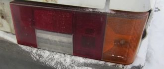
Turn signals do not work on VAZ 2107, 2105, 2104, reasons
The turn signals (turn signals) of VAZ 2107, 2105, 2104 cars may not work due to their malfunction or failure of any element of their electrical circuit. There are several options for failure of turn signals:
Causes of the malfunction: the direction indicator of the VAZ 2107, 2105, 2104 does not work
– The turn signal does not work, reasons
The indicator light is burnt out
A burnt-out light bulb visually indicates a broken filament. In some cases, the light bulb may look fine, but it will not work. Therefore, we replace the light bulb with a new or known one.
The contacts in the socket are oxidized
We turn the light bulb in the socket several times or remove and clean the contacts.