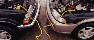
Connecting high-voltage wires ZMZ 405, ZMZ 406
ZMZ carburetor and Euro-2 engines are equipped with a DIS (Double Ignition System) ignition system.
The DIS system uses ignition coils with two high-voltage wires. Each coil operates a corresponding pair of cylinders.
The first coil works with 1 and 4 cylinders, the second coil works with 2 and 3 cylinders.
How to connect the ignition coils?
The ignition coil of cylinders 1 and 4 is located closer to the intake manifold, the coil of cylinders 2 and 3 is closer to the exhaust manifold.
Low-voltage coil wires must be connected to the coil in pairs. The pair of wires for coil 1-4 is slightly shorter than the pair of wires for coil 2-3.
Within the pair, it does not matter which contact is connected to which wire - the coils are non-polar. Also, within the pair, it does not matter which high-voltage wire goes to which cylinder.
Let's look at an example (see photo)
Coil 1 control (cylinders 1 and 4) – green and yellow wires. This pair connects strictly to the coil of cylinders 1 and 4!
Low voltage circuit - polarity is not important - can be connected:
Option 1: The top coil contact is yellow, the bottom contact is green.
Option 2: The top coil contact is green, the bottom contact is yellow.
High voltage outputs – polarity is not important – can be connected:
Option 1: Top outlet for cylinder 1, bottom outlet for cylinder 4.
Option 2: Top outlet for cylinder 4, bottom outlet for cylinder 1.
Coil 2 control (cylinders 2 and 3) – blue and yellow wires. This pair is connected strictly to the coil of cylinders 2 and 3! Further - similar to pair 1-4 - the polarity within the pair is not important.
The determining factor when connecting pairs of low-voltage and high-voltage wires to the corresponding ignition coil is the correctness of their routing. The wires should not be too tight, bent too much, and should not rub against fixed parts of the engine or other wires.
Another article about high-voltage wires ZMZ 405, 406 - read so as not to repeat this mistake.
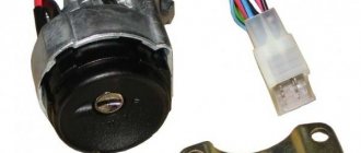
The ZMZ-406 engine is equipped with a microprocessor ignition system, which consists of a control unit for fuel injection and ignition systems, two ignition coils of types 30.3705 or 301.3705, spark plugs, high-voltage and low-voltage wires.
The control unit is installed in the car interior on the right side under the instrument panel, behind the body side upholstery.
The ignition coils are installed on the cylinder head cover.
The control unit receives signals from sensors installed on the engine and, based on this, adjusts the ignition timing, which allows for optimal power, economic and toxicity indicators.
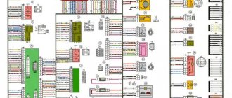
Electrical diagram of an integrated microprocessor engine control system (KMSUD)
Ignition coil
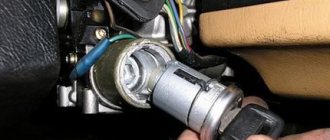
1. Disconnect the wire from the negative terminal of the battery.
2. Disconnect 4 blocks 1 of low-voltage wires and high-voltage wires 5 from the coil.
Unscrew bolts 2, remove bar 3 and coil 4.
3. Remove the second coil in the same way.
Examination
1. Coils 30.3705 and 301.3705 are checked with a spark plug diagnostician 1AP975000 on a car.
To do this, disconnect the high-voltage wires from the coil and connect the diagnostician instead.
Then crank the engine with the starter, while a spark should jump in the diagnostic spark gap in time with the operation of the cylinders.
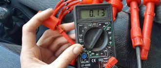
2. Check the resistance of the primary winding of the ignition coil by connecting an ohmmeter between the low voltage terminals.
The ohmmeter should show a resistance of 0.025–0.03 ohms.
Then check the resistance of the secondary winding by connecting an ohmmeter between the high voltage terminals of the ignition coil.
The ohmmeter should show a resistance of 4000–5000 ohms.
If the measured parameters differ from those specified, the coil must be replaced.
Install the ignition coil in the reverse order of removal.
How is a spark formed at a spark plug? According to the theory of electrical engineering, a voltage of 3000-4000 volts is required to break down 1 mm of ideal air space. In the interior of the cylinder block, the conditions are more stringent, but in any case, an uninterrupted supply of electricity is important for spark plugs. Thousands of volts are generated by the coils or ignition module; their description deserves a separate article.
To eliminate the weak link, some manufacturers install bobbins directly on the spark plugs. This makes the system more reliable and, accordingly, more expensive. We will look at the classic circuit: coil - high-voltage ignition wires - spark plug.
Car enthusiasts call ignition wires differently: spark plug, bobbin wire, armored cable. We are talking about the same product.
Pistons
They are cast from aluminum alloy and have grooves for two compression rings and one oil scraper ring. During operation, the piston crown is cooled by oil through an oil nipple in the upper end of the connecting rod.
The spherical working surface of the upper compression ring has a layer of chrome coating, which facilitates better grinding of the ring. The second element is coated with a layer of tin. The oil scraper ring is of a combined type; it consists of an expander and two steel discs. The piston is attached to the connecting rod using a pin fixed to two corkscrew rings.
What are the requirements for spark plug wires?
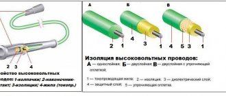
Any conductor has a certain service life. If the cables are laid in a bundle, have an outer braid and are fixed permanently (protected from vibration loads), the service life is equal to the life expectancy of the car. Another thing is the high-voltage ignition coil wire. It is located in the epicenter of unfavorable conditions: vibration, high temperature (as well as changes in winter), gasoline vapors, therefore high demands are placed on the quality of insulation of high-voltage wires and the core:
- The conductors are exclusively copper (as is known, this material has the lowest resistance), but the protective layer can be silicone or rubber. Other insulation materials, although they have good protection, are not soft enough. Another requirement for high-voltage wires is elasticity. Otherwise, the surface will simply crack due to constant vibration;
- Shell thickness is a compromise. If a breakdown of high-voltage wires occurs, a spark will form between the central core and the motor housing. The voltage will not reach the spark plug, but the presence of a sparking conductor in the engine compartment, to put it mildly, is not useful for the car. The other side of the coin is that a wire that is too thick is inconvenient to install, it is inelastic, which makes installation and maintenance difficult;
- The length of high-voltage wires is another headache for the manufacturer. From Ohm's law it is known: the shorter the conductor, the less losses for electric current. In a car, it is not so easy to place all the interacting components next to each other. Mounting the ignition coil above the spark plug wells is good for electricians, but bad for builders. In addition, it is desirable that the cables be of similar length, so the connection diagram for high-voltage wires is carefully calculated, and replacing the cables with universal ones means disrupting the operation of the entire ignition system on the car.
Replacing wiring
Advice: replacing functional control devices on the panel due to new connectors is not justified.
Therefore, when integrating new wiring, the connection diagram in the connecting terminals only changes, and for alignment you should use the wiring diagram of the new power unit.
It is certainly not impractical to change the entire electrical wiring of the Gazelle when replacing the engine from 402 to 406.
The fact is that on newer versions of Gazelles, the connection diagram of certain devices also changed:
- Gazelle 406 wiring is integrated into the standard electrical system in the engine compartment;
- electronic components and control devices are connected using terminals;
- The voltage and correct connection are checked using testers.
High-voltage wire tip - what is it for?
Connection in the traditional way is not possible. The tips of the candle should be easily removable, but provide reliable contact. As a rule, the caps are made of a solid dielectric, although there are exceptions. Rubber adheres better to the walls of the spark plug well and ensures tightness. However, this material is subject to wear and tear. Plastic dielectric is more durable, but moisture can condense underneath it. Which material to choose is decided by the manufacturer depending on the design of the cylinder head.
There is one wire coming from the ignition coil; distribution to the spark plugs occurs on the distributor. Depending on the engine design, the four-cylinder version has up to ten tips. Just like the main wires, caps can cause breakdown or loss of contact. Water gets under them, the material cracks, and a spark “pierces” the spark plug insulator.
A little theory
High-voltage wires (hereinafter referred to as HV wires) are divided into two groups. With metal and non-metal core. In turn, the second group is divided into products with a resistive core and an inductive one. I will not delve very deeply into the theory, I will only note that the resistance of the old-style wires (copper internal conductors) and the new-style wires (non-metallic conductor) differs by an ORDER. The permissible resistance of the high voltage wire is considered to be up to 20 kOhm, normal is up to 10 kOhm. The resistance of wires with a non-metallic core is no more than 1-2 kOhm per meter of wire.
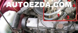
The procedure for connecting high-voltage wires
If the cables are the same length, they can be easily mixed up. The output device must have cylinder markings. An incorrect connection will cause the spark sequence to be disrupted. In the best case, tripping or detonation will occur, in the worst case, the engine simply will not work. In order to follow the order of connecting high-voltage wires, it is recommended to photograph the process before dismantling them, or mark the caps in accordance with the cylinder numbers.
If the distributor (ignition module) is located at the end of the cylinder block, the length will be different, and replacing high-voltage wires will not cause difficulties.
Crankshaft
Cast from cast iron with subsequent processing and hardening of the surface of the journals with high frequency currents. It is installed in the block on five main bearings.
The movement of the crankshaft according to the axis is limited by corkscrew half-rings, which are located in the flow grooves of the support and the cover of the third main bearing. There are eight counterweights on the shaft. A flywheel is attached to the rear of the shaft, in the hole of which a spacer sleeve and a rolling bearing of the gearbox input shaft are pressed.
Malfunction of high-voltage wires: symptoms and consequences
The general symptoms are similar to problems with spark plugs (unless the injector is to blame for the failure), so before checking the high-voltage wires, make sure that the remaining engine components are in good working order.
- Problems with starting - the spark plugs do not receive enough voltage. This could be a broken wire or corrosion of the tip contacts. The malfunction is typical for an engine that is not warmed up;
- The engine “shoots” at start; If it starts, it runs unevenly, with increased vibrations. The order of connecting high-voltage wires is violated;
- Ragged operation at idle. The connection with the candle is lost due to vibration;
- Violation of CO emission standards. The problem is accompanied by periodic tripping of the motor. One of the cylinders misfires and the fuel does not burn completely;
- Interference on the multimedia system: the character changes when the crankshaft speed changes. In the slang of car enthusiasts, high-voltage car wires are “sewn to ground.” Multiple discharges on the motor housing create “thunderstorm” interference;
- Smell of ozone under the hood. The reason is the same as in the previous paragraph: high-voltage wires penetrate the housing.
Injection motor
In terms of technical characteristics and components, an engine with an injection power system is not very different from the carburetor analogue of the 405 model.
With proper operation, this unit is no less reliable and practical than with a carburetor, and in addition has its own advantages:
- Stable idle speed.
- Low level of harmful emissions into the atmosphere.
- The efficiency of the ZMZ-406 injector is much higher than its analogue with a carburetor, since the fuel mixture is supplied in a timely manner and in the right quantity. Accordingly, fuel savings are obvious.
- Improved fuel economy.
- Does not require prolonged engine warm-up in winter.
Checking high-voltage ignition wires using improvised means
If your car is equipped with an OBD port, you can localize the fault to at least the cylinder number. The most primitive scanner (such as ELM 327) will show misfire or lack of ignition. With any method of identifying a problem area, it is better to test the wires in the removed state. For a complete test, you will need a voltage multiplier and a megohmmeter (to check the insulation). Wires are connected to the high voltage source and laboratory tests are carried out. As a rule, there is no such equipment in the garage, so we will use a multimeter.
The test begins with a visual inspection. There should be no cracks on the insulation, no black points of spark breakdown, the cable should bend with the same force in any place. Tips without oxides or breaks. The caps are intact, with the same thickness of the skirt.
Then we measure the resistance of the high-voltage ignition wires. On all armored cables it should be approximately the same - within 2 kOhm - 10 kOhm. Exactly what value depends on the manufacturer. The denomination can be found in the product passport. It is impossible to replace high-voltage wires with non-standard ones (from another car), their resistance is calculated according to the capabilities of the ignition coil. Faulty ones must be rejected: repair of high-voltage wires inside the insulation is impossible.
Important! Connecting the multimeter probes must have good contact, otherwise you may introduce a high error in the measurement.
What is needed for remodeling
If you modernize it, it will be completely, including the injector, and for this you should take a closer look at the Digitronic gas-cylinder equipment. This HBO is praised by many, and it can be installed on Gazelle.
Many people know about the economical consumption of a car with LPG.
But there is one significant nuance - to equip a car with Digitronic, you need an injection engine, “tuned” to Euro-2 toxicity standards.
And then, modifications for the injector will not end there, because the following components and parts will be needed:
- Injector wiring on the Gazelle - 406 engine does not have it, not to mention the control unit;
- Intake system, including the manifold itself with the injector ramp, throttle position sensor, throttle pipe, idle air control and additional air regulator, connecting pipes and pipes;
Checking high-voltage ignition wires without removing them from the car
This is a primitive but quite effective method. The simplest option is to install a known-good cable and compare the operation of the engine. If the location of the high-voltage wires allows, you can swap them (along with the connector on the distributor), and again read the errors with the scanner. It will indicate a different cylinder number.
Putting a dielectric glove on your hand, you can remove the tips from the spark plugs one by one while the engine is running. When you reach the problem cylinder, the nature of the work will not change.
Definition of breakdown “by eye”. In the dark you can see how the spark “sews” onto the body of the internal combustion engine. You can connect a thick wire to ground and run the bare end along the insulation. You will see the weak point immediately - a spark will strike.
Despite a whole bunch of breakdowns that armored wires can cause, their solution is no more difficult than replacing plugs in a home electrical panel. If a faulty one was identified, a new one was installed. If there is a problem, how to change high-voltage wires on the highway or in an open field (far from stores), remember that the cables do not break suddenly; regular diagnostics will help you not to be caught by surprise.
FakeHeader
Comments 15
I read it, even the first time))
And my engine dangles back and forth at idle. CHANGED SPARKLES WIRES COILS MARKS SENSORS ALL