The performance of the automotive ignition system (ISY) directly affects the functionality and operating condition of the vehicle engine. Accordingly, the failure of one of the system elements can lead to minor or even serious problems in the operation of the power unit. What is the operating principle and order of the SZ, how to replace the Gazelle ignition switch - read more about this below.
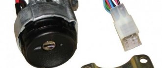
Gazelle ignition switch pinout 5 pins
The quality of the ignition system of foreign and domestic cars affects the performance of cars.
Obvious problems result in frequent failures or the inability to start the engine in a timely manner. In most cases, the problem is caused by the electrical part of the ignition switch. Trucks of the GAZ family and buses can fail their owners due to burnt or oxidized contacts. To restore the functionality of the unit, we recommend studying what the Gazelle ignition switch circuit looks like.
Gearbox gearbox for GAZ A21R22 NEXT N/O (A21R22-1700010-01)
- Product description
- Payment
- Delivery
- Warranty and exchange
The new model gearbox (gearbox) for the GAZelle-NEXT A21R22 car is a mechanical unit that ensures the transmission of torque from the engine to the wheelbase, changing the number of this torque. It is clear that such an important function makes the gearbox one of the main components in every car. Understanding the importance of equipping our customers' cars with only the highest quality gearboxes, we offer gearboxes for GAZ and PAZ directly from the manufacturers, completely eliminating the possibility of including counterfeits in our range.
Advantages of "AutoGip52"
| Extensive work experience | More than 2000 items in stock | Active discount system | Low prices | Individual approach to each client | Every day the warehouse is replenished with new goods |
AUTOGYP 52
The online store "Avtogip52" sells a wide range of original spare parts for cars of domestic brands GAZ, PAZ, UAZ, ZIL. The product catalog includes components for the following models: Gazelle (including modifications Business and Next), Valdai, Sobol, GAZ-3307, 3308, 3309, 4301, GAZ-53, 66, Lawn Next.
How does the ignition system work?
The system for models with a 402 engine functions similarly to those systems installed on cars with a 406 engine or in a five-seater vehicle. The main tasks performed by the installation are based on the accumulation and subsequent transformation of voltage from low voltage to high voltage. Coils are used for this.
The voltage converted from the coil is sent to the spark plugs screwed into the block. A spark is formed between the spark plug electrodes, which ignites the combustible mixture. The main stages for the Gazelle ignition system are:
- formation of sufficient charge with low voltage;
- raising the charge to high values;
- redistribution of impulse between candles in the sequence specified by the manufacturer;
- sparking at the tips of spark plug electrodes;
- timely ignition of the air-fuel mixture.
To start the rotation of the engine crankshaft, a starter built under the hood is used . Voltage begins to be supplied to it after turning the key to its extreme position.
Repair work with lock
The driver may encounter a situation in which the motor does not respond after turning the key. One of the probable reasons is a poor connection in the contacts or the connection diagram of the Gazelle ignition switch has been broken. You can carry out repairs yourself in a garage.
With each new start of the engine, the starter may not start the first time, but after 3-4 attempts. Blaming the battery is not always correct. You should look for the cause in the ignition switch, where its switch is located.
Testing begins by disconnecting the electrical connector. Next, using a small piece of wire with uninsulated ends (a bug 6-7 cm long), we close the contacts in the wires of the block suitable for the lock. It is necessary to clarify in advance which wires will be closed in the first position of the key according to the diagram. Next, using a similar bug, we close the starter contacts for a short time (1-2 seconds).
If all operations are tested correctly and respond to the driver’s actions, then it is necessary to repair the contact group or the lock as a whole. The operation begins with dismantling the casing. At the next stage, remove the plastic cover, behind which the ignition switch itself is hidden.
The designers provided for its fixation in the groove to prevent rotation during operation. To assemble, return the plastic cover to its place, screw on the casing and connect the connector.
It is important to know that the cost of the ignition switch is less than 200 rubles.
The pinout of the Gazelle 5-pin ignition switch is slightly different. It is shown in the picture.
conclusions
GAZelle cars (see Gazelle wiring diagram) will be the main vehicle of Russian entrepreneurs for a long time. This means that independent car maintenance will continue to require high-quality schemes that will allow us to understand the causes of technical failures.
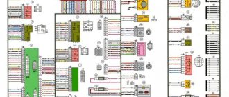
Schematic electrical diagrams, connecting devices and pinouts of connectors
The ignition switch in cars of the VAZ family fails from time to time due to weakening of the contact posts or burning of the contacts inside it. It also happens that the cams of a plastic roller are produced. You can disassemble the lock and clean it, but it’s better to just replace it with a new one, considering that it costs pennies compared to imported locks.
But if connecting the wires together did not result in the starter operating (or it did not turn on the first time), check the solenoid relay on the starter. The contact spots on it may also burn out, which will prevent the circuit from closing normally. Alternatively, you can use a screwdriver to short-circuit the two large terminals on the solenoid relay (before doing this, put the car in neutral and use the handbrake). When closed, the starter should begin to spin vigorously. If this happens, remove and change the solenoid relay. If the starter rotates “sluggishly” when it closes, you will have to remove it and check the condition of the brushes.
All operations are performed with your own hands, without the help of car service specialists. Moreover, the price of an ignition switch on a VAZ2106 is up to 100 rubles. To replace it, you will need to know the pinout of the wires coming from it, for which the editors of the site 2 Schemes.ru have prepared a large reference material.
The ignition switch is designed not only to start the engine - it performs several functions at once:
- supplies voltage to the vehicle’s on-board network, closing the circuits of the ignition system, lighting, sound alarm, additional devices and instruments;
- at the driver’s command, turns on the starter to start the power plant and turns it off;
- turns off the power to the on-board circuit, preserving the battery charge;
- protects the car from theft by fixing the steering shaft.
Complete lock replacement
To install a complete lock, you must first remove the contacts from the battery. Then you need to perform the following operations:
- We dismantle the casing;
- to remove the clamp, carefully use a grinder so as not to damage the main axis of the steering column;
- experts recommend turning off the steering column so that subsequent operations can be carried out conveniently, while the steering wheel is raised to its maximum height with preliminary loosening of the fixing bolt with a 12mm wrench;
- It is worth sketching or remembering the position of the curly bracket installed next to the head of the fixing bolt for subsequent comfortable assembly;
- dismantle the old ignition;
- we use a new bracket, make slots in the sides where the heads of the lag screws are supposed to be placed, otherwise the heads will rest against the edges, which will not allow them to be securely fixed;
- put the lock in the seat and screw in 4 screws with maximum force;
- A couple of 12 nuts, unscrewed in advance, should not be tightened to the maximum, so that there is still freedom to adjust the clamp.
Before installing the casing, we test the assembled unit for functionality. If problems arise, we bring the adjustments to working condition, and only then install the decor.
Problems when paying with bank cards
Sometimes difficulties may arise when paying with Visa/MasterCard bank cards. The most common of them:
- There is a restriction on the card for paying for online purchases
- A plastic card is not intended for making payments online.
- The plastic card is not activated for making payments online.
- There are not enough funds on the plastic card.
In order to solve these problems, you need to call or write to the technical support of the bank where you are served. Bank specialists will help you resolve them and make payments.
That's basically it. The entire process of paying for a book in PDF format on car repair on our website takes 1-2 minutes.
>
The principle of operation of the Gazelle ignition system
First, let's look at the operating principle of the SZ Gazelle 402 engine. In this case, we are talking about any models of this car - both with a 406 engine and 5-seater Gazelles. The principle of operation of the SZ lies in the accumulation and further conversion of low-voltage voltage into high-voltage voltage using a coil after that. After conversion, the coil transmits and distributes high-voltage voltage to the spark plugs of the system. The spark plugs themselves are used to generate a spark, which, in turn, is necessary to ignite the air-fuel mixture in the cylinders.
- accumulation of low-voltage charge;
- converting it to high voltage;
- distribution of impulse over the corresponding candles in a certain order;
- creating a spark on the spark plug electrodes;
- ignition of a flammable mixture.
Pinout of Gazelle ignition switch contacts
Firing order
The connection diagram for the cylinders on the Gazelle, that is, the order of their activation, for the 406 engine is as follows:
- first the mixture ignites in the first cylinder;
- then the caviar is served on the third;
- after that - to the fourth cylinder;
- The second cylinder is the last to start working.
Basic elements of SZ
Briefly about the main components of SZ:
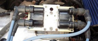
- an ignition module that includes several coils;
- switching device;
- distribution mechanism;
- candles;
- spark plug tips;
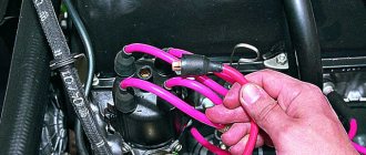
- elements connecting the spark plugs to the coil are high-voltage cables.
General information
The electrical wiring diagram in a GAZ car with a carburetor or injector engine consists of many components.
And it doesn’t matter whether it’s Gazelle 402, 405, 406, 3302, 2705, Business or Euro, the electrical circuit will include the following subsystems:
- Ignition system. This unit consists of different components, the main ones being the switchgear, spark plugs, and high-voltage wires that transmit the charge. The functionality of the engine and its operation in principle depend on the performance of this system.
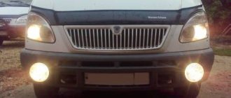
- Optical system. It includes all external headlights, from headlights to brake lights and fog lights.
- Lighting in the car interior, including on the dashboard.
- Electronic engine control system (depending on the car model).
- Windshield cleaning system, which includes an electric motor and windshield wiper blades.
- A fuel system, one of the main components of which is the pump.
- Battery and generator unit.
- Audio system, if available, etc.
How does the ignition system work?
The system for models with a 402 engine functions similarly to those systems installed on cars with a 406 engine or in a five-seater vehicle. The main tasks performed by the installation are based on the accumulation and subsequent transformation of voltage from low voltage to high voltage. Coils are used for this.
The voltage converted from the coil is sent to the spark plugs screwed into the block. A spark is formed between the spark plug electrodes, which ignites the combustible mixture. The main stages for the Gazelle ignition system are:
- formation of sufficient charge with low voltage;
- raising the charge to high values;
- redistribution of impulse between candles in the sequence specified by the manufacturer;
- sparking at the tips of spark plug electrodes;
- timely ignition of the air-fuel mixture.
Blog about UAZ
GAZelle GAZ-3302 and GAZ-2705 vehicles with ZMZ-4025 and ZMZ-4026 engines are equipped with a non-contact ignition system. Before checking the engine ignition system, place the gear shift lever in neutral and leave the parking brake on.
Checking the serviceability of the contactless ignition system of GAZelle GAZ-3302 and GAZ-2705 with the ZMZ-4025 and ZMZ-4026 engines, supplying emergency power to the ignition system.
Then, with the ignition off, first check:
— Integrity and fit of high-voltage wires in the ignition distributor cover. — Placement of the high-voltage wire in the ignition coil. — Integrity of the wires coming from the distributor to the switch and their connections. — Planting the wires connecting the switch and the ignition coil.
Lock replacement and repair
If, when you try to turn on the key, nothing happens in the lock, that is, the engine does not start, the problem may lie in a poor connection of the contacts. You can try to repair such a lock, but if this does not help, then the device will have to be changed (the author of the video is Sergey Vishnyakov).
Replacing the contact group
This task is performed as follows:
- First you need to disconnect the battery, to do this, remove the negative terminal from it. Next, the protective lining of the steering column is dismantled. Using a flat head screwdriver, you will need to remove the two bolts that secure this shroud.
- Having done this, you can dismantle the upper part of the lining.
- Next, the steering column is moved to its highest position. You will need to slightly tilt the top of the cover towards you until the fastenings of this part of the casing come out of the slot.
- Then the lining is dismantled; it must be moved upward.
- Using a flat-head screwdriver, you will need to unscrew the two bolts that secure the contact part of the lock. Then the contact component is removed and replaced with a new one, further assembly is carried out in the reverse order.
Photo gallery “Changing the contact group”
Changing the lock
To completely change the lock, do the following:
- As in the previous case, you first need to remove the protective casing.
- It will not be possible to dismantle the clamp, since the standard nuts do not have edges, so it must be cut, for example, with a grinder. Be careful not to damage the steering column tube.
- Next, you will need to disable the steering column - this is done to make the further replacement procedure more convenient. First, the long screw connected to the steering wheel height adjuster is unscrewed. After this, the steering wheel itself should be lifted up, this will allow you to unscrew another bolt; for this, use a 12-mm wrench. When removing the screw, you will need to remember the position of the brace; it is located next to its head.
- The next step will be to remove the old ignition.
- Now take the new bracket and make slits in the sides where the lag screw heads will be located. The slots are a must because they will allow you to easily tighten the four lag screws. If the slots are missing, this will lead to the heads on the ratchet resting on the edges, so it will not be possible to securely fix the device.
- Next, the device is placed in the seat, four screws are tightened, they need to be tightened to the maximum. The two 12mm nuts that you unscrewed earlier do not need to be fully tightened, as this will result in you not being able to adjust the position of the steering wheel. Assemble the entire structure and test the operation of the installed lock.
Downloading a book
After successfully completing the payment (by any method) and returning to the KrutilVertel store from the payment system website, you will be taken to the successful payment page:
On this page you need to indicate your e-mail, where access to download the book will be sent.
If you are already registered on our website, then simply follow the link to your personal account.
The book you purchased will be in your personal account, from where you can always download it.
Please note that after making the payment, you need to return back from the payment system website to the KrutilVertel website.
If for some reason you did not return back to the site and closed the payment system tab with a message about the successful completion of the payment, please let us know - we will send you a letter indicating access to download the book.
Ignition switch gas 3110 wiring diagram. Connecting the ignition switch gazelle
ignition switch gas 3110 wiring diagram
Mr. Stability Uploader 100+
ignition switch gas 3110 wiring diagram
To check the ignition switch, sequentially set the key to the positions at which the circuits indicated in the table should be closed.
When the key is turned to position “III”, the anti-theft device should be activated. When turning the key from position “III” to position “0”, the anti-theft device should turn off. This can be checked by turning the steering wheel.
When restarting from position “I” to position “II”, the locking is activated. The key can only be turned to position “II” from position “0”.
If there are defects, replace the contact group or ignition switch.
Outdoor Lighting. Instrument lighting. High beam headlight alarm
Generator excitation winding. Ignition system. Windshield cleaner. Carburetor idle speed solenoid valve control unit. Direction indicators. Reversing light. Control devices
Low and high beam headlights. Fog light. Headlight cleaners. Rear window cleaner. Heated rear window. Washer. Heater fan. Engine cooling fan
Remove the six screws securing the lower steering column housing.
Remove the lower steering column cover.
. and ignition switch trim.
Remove the upper steering column cover.
Disconnect the ignition switch wiring harness from the wiring harness.
Disconnect the block with the ignition switch wires from the ignition relay.
Insert the key into the ignition switch and turn it to the “0” position to turn off the anti-theft device. Unscrew the four mounting bolts (two bolts are located on top of the column). Remove the bracket and ignition switch (see notes 1 and 2).
If the bolt heads are sheared off, the bolts must be drilled out or removed using a screwdriver and hammer.
Some cars are equipped with an ignition switch secured with two bolts. There is a slot at the top of the bracket that accepts the hook on the ignition switch housing.
Unscrew the screw securing the switch cover.
Remove the switch trim by pressing out the two plastic latches with a screwdriver.
Remove the contact group.
Assembling and installing the ignition switch is carried out in the reverse order.
Illumination of the instrument panel - how is the panel arranged?
Any modern car must have lighting for both the instrument panel and other buttons and switches located on the car’s dashboard. Illumination of the ignition switch is a very common occurrence in imported cars. Our manufacturers have not thought of this, so many drivers improve their iron horse on their own. Such lighting will give your car a special charm at night, and it’s convenient to see where to insert the key.
Photo of the ignition switch illumination
The most optimal and common type of lighting in our time is the illumination of the ignition switch using LEDs.
It is not difficult to install, and its service life is very long. The most important thing is that when choosing such lighting you don’t need to invent anything. Car dealerships, as a rule, sell standard types of backlights that have only one bulb and can only shine at a point. For VAZ cars, they began to produce ready-made elements for illuminating the ignition switch, which are conveniently mounted and do not require alterations or cutouts in the plastic of the car’s steering column.
Wiring diagram for Gazelle 402 engine: do-it-yourself replacement
Did you like the article? Follow our channel for new ideas of useful car tips. Subscribe to us in Yandex.Zen. Subscribe.
Having become an indispensable vehicle, the Gazelle with the 402 engine still requires attention over the years.
Electrical wiring is not listed among the parts subject to scheduled replacement, however, an electrical diagram is often required when carrying out repair work in the engine compartment.
Equipped with a ZMZ-402 carburetor engine, the car successfully exhausts its service life, and when the time comes for a major overhaul, many owners think not only about restoring, but also about reconfiguring its operation.
And since carburetor versions of power units have become a thing of the past, the question of the prospects for using a restored engine is urgent.
About classic UAZ SUVs and off-road vehicles
Domestic realities When using a Gazelle car, the owner needs an electrical wiring diagram in order to be able to find faults that are caused in the power and ignition system by poor-quality fuel and harsh operating conditions: Climatic features manifest themselves in winter, when the load increases significantly, especially during morning start-up periods power unit; Interruptions and even failures of the air-fuel mixture injection and ignition system can occur at any time of the year; Other circuit faults, contact desoldering, corrosion caused by poor build quality.
Electrical diagram of the UMZ engine control system Although it’s worth dwelling on this a little.
Cars with such engines received their own names among motorists - Gazelle from the UMZ engine, Gazelle from the ZMZ family of engines. Although the diesel engine is free of the ignition system traditional for gasoline-powered engines, its design contains a lot of other electrical components, including the main these are: Fuel pump control unit; Exhaust gas afterburning system control unit.
The ignition timing control system uses a GT sensor or Since the year, ABS has become the basic equipment of minibuses intended for transporting passengers. Although the diesel engine is free of the ignition system traditional for gasoline-powered engines, its design contains a lot of other electrical components, the main ones of which are: Fuel pump control unit; Exhaust gas afterburning system control unit. But here's what I noticed.
See also related news
Conclusions: exposing cars. The photo shows the first part of the original diagram. And the Gazelle electrical wiring differs primarily due to the installation of imported components, which requires high-quality instructions, which car owners often do not have. The next difference is a slightly more complicated heater switching circuit.
Electrical system of a Gazelle car
The transition to multi-valve injection engines is possible and even recommended by the automaker, but owners are not always satisfied with this approach, especially from the financial side.
Advice: Be that as it may, when removing the motor for overhaul, the owner has the opportunity to replace the old electrical wiring.
If the resource of the restored power unit inspires optimism, and you have a Gazelle wiring diagram at hand, the 402 engine may well last for hundreds of thousands of kilometers.
Replacing wiring on a Gazelle car
The reasons causing the need to replace the electrical wiring according to the diagram in Gazelle cars are not only due to the overhaul of the power unit, but also:
- Due to natural wear and tear of wires;
- Delamination of insulation due to natural aging;
- Mechanical damage (kinks, scuffs);
- Short circuits in one or another electrical circuit;
- Oxidation of contacts and connectors.
Additional replacement materials
In addition to purchasing new electrical wiring, those corresponding to the motor used must also be replaced:
- High voltage wires;
- Electronic switch (in later versions of motors of the ZMZ-402 series);
- Ignition coil;
- Battery charge level relay;
- Fuse block contact group;
- Egnition lock.
Places requiring installation work
Laying the wiring harness is not a difficult task, especially since the places for their attachment to the frame are provided initially (gutters, service holes, etc.).
However, according to complexity, replacement work is divided into areas of responsibility:
The easiest part in terms of connection is the rear part of the car, where you only need to secure the harness and connect the rear lights and the fuel level sensor in the gas tank. The interior and engine compartment are more complex.
Technical differences
Electrical wiring for Gazelle 406 under Mikas 7.1
A power unit that has exhausted its service life is replaced, often giving preference to more modern versions.
Structurally, everything fits into the factory seats, and the differences, for example from the Gazelle Business, appear only in the electrical wiring diagram at the location of the equipment:
- Another form of connecting blocks;
- A different diagram for connecting devices;
- Different voltage.
Supply system
Leaving the carburetor in the past, replacing the power unit inevitably entails replacing the power system:
- A new gas tank is installed, since the injector must dump excess fuel back, and the old tank design is not suitable for this;
- The gas line is replaced (the return line is laid + the supply connection is modified);
- The operation of the injectors is regulated using connecting wiring.
Cooling system
The new injection engine ZMZ-406 is more demanding on the cooling system, therefore, during the installation of a new power unit:
- An electric fan is installed on the cooling radiator;
- The engine compartment wiring harness is being replaced.
Fuel injection control system
Mikas control unit, connected in the engine compartment
Do not forget that the power supply system of the injection engine is controlled by an electronic unit, which also needs to be connected to the car’s standard electrical network. Accordingly, the electrical wiring on the Gazelle 406 is different than on older versions of the car with 402 series engines, and must be replaced.
Complete lock replacement
To install a complete lock, you must first remove the contacts from the battery. Then you need to perform the following operations:
- We dismantle the casing;
- to remove the clamp, carefully use a grinder so as not to damage the main axis of the steering column;
- experts recommend turning off the steering column so that subsequent operations can be carried out conveniently, while the steering wheel is raised to its maximum height with preliminary loosening of the fixing bolt with a 12mm wrench;
- It is worth sketching or remembering the position of the curly bracket installed next to the head of the fixing bolt for subsequent comfortable assembly;
- dismantle the old ignition;
- we use a new bracket, make slots in the sides where the heads of the lag screws are supposed to be placed, otherwise the heads will rest against the edges, which will not allow them to be securely fixed;
- put the lock in the seat and screw in 4 screws with maximum force;
- A couple of 12 nuts, unscrewed in advance, should not be tightened to the maximum, so that there is still freedom to adjust the clamp.
Before installing the casing, we test the assembled unit for functionality. If problems arise, we bring the adjustments to working condition, and only then install the decor.
Installation of wiring on a Gazelle car
The wiring for Gazelle 402 is divided into the indicated zones.
Having laid out a new set of wires in a free place, its orientation will be immediately noticeable:
- The longest and thinnest tourniquet is intended for the back;
- The shorter one is for the interior;
- The largest number of wires and connectors is for the engine compartment.
The start of work on replacing the wiring is carried out from the cab:
- We fix the tourniquet in the cabin;
- We drag the second wiring harness under the hood and secure it;
- We drag the rear harness along the frame, connect the connectors, focusing on the colors of the wires;
In the engine compartment:
- We divide the harness into the right and left sides, focusing on the length and connectors;
- Connect the switch;
- We feed the wire to the generator;
- Connect the voltage regulator;
- Connect the ignition coil;
- We connect the terminals of the windshield wiper, turn relay;
Tip: the Gazelle 402 wiring is divided into colors that correspond to the colors shown in the diagram, as well as on the Gazelle Business wiring.
- We connect the connector to the fuse block;
- We feed the wire to the heater;
- We connect the light switch to the steering column;
- On the instrument panel, we power the central head light switch, the hazard warning button, and connect the devices.
Conclusions: using the factory wiring diagram of the Gazelle, regardless of the model - 406 or another, you can independently replace the old wires, adhering to the symbols and color designations.
Element structure
A standard ignition switch includes two parts:
- mechanical - a locking part in the shape of a cylinder, inside of which the ignition key is inserted;
- electrical - a contact element consisting of a part of the contacts that is closed taking into account the standard algorithm during the turning movement of the key.
As a rule, a cylindrical lock is installed in the ignition key, the task of which is to rotate the contact assembly and block the steering wheel. For the purpose of blocking, a locking element is used; it comes out of the lock body during the turning movement of the key and goes into the groove part of the steering column. The structure of the ignition lock has a simplified design; this part consists of a body part, a bracket, a facing part with a contact element and a lock with a fixing pin and a hole for it.
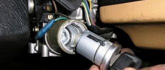
Gazelle Ignition Switch
Ignition switch
We are changing the ignition switch. I decided to change it because... It often happened that the key slipped, and already, the engine was running, but the starter was still spinning. You would start Plus, but the heater didn’t work, the low one didn’t light up (the key had to be moved here and there) I CHANGED IT IN 25, MINUTES ALREADY THE SECOND REPLACEMENT, the first was the first on the car, there I changed the hour. The best thing I bought a cheap one, I didn’t take Nizhny Novgorod for RUB 800. and it works fine (on an old, proven machine) Now I already know how to come up with something, modify it. I’ll explain in detail, because If people are faced with a replacement for the first time, then it will be incomprehensible to them anyway. If it’s problematic, read and also change it in 25 minutes))))) Disconnect the plug in advance.
1. Undress the steering wheel, remove the top and bottom plastic, the bottom one is problematic to remove, to do this, bend the steering wheel adjustment knob (first of course, unscrew the 2 screws of the ridge strip). Using a screwdriver:
2. It’s impossible to remove the clamp, the factory ones have no edge nuts, we cut them with a grinder mercilessly, the main thing is to stop in time, otherwise you’ll cut the main column steering pipe.
3.Cut a small piece and it should, well, fall off a couple of times with a hammer.
4. For further convenience, I unscrewed the steering column itself. This is the long bolt that goes to the steering wheel height adjuster. It was unscrewed, on the left 2 on the right by 12, the nuts on the bolt head by 12. To remove this bolt, without any extra effort. Raise the steering wheel as much as possible. up. When you take it out, look at the bolt and remember the position of the brace (the head of the bolt). And then stick it in as well.
5. The steering wheel and steering column have fallen. We take out the old one. Give the ignition to his neighbor or mother-in-law (in the old ones with the keys included).
6. We take a new bracket and make slots in the sidewalls where the heads of the tightening bolts will be. And these slots are so that you can then easily tighten the 4 tightening bolts with a ratchet; if you don’t make the slots, the head will rest against the edge of the ratchet, and you won’t tighten the ignition suddenly. Yes, and maybe again you’ll have to remove the ignition yourself.
7. It’s just a matter of small things: we put the part on the left handlebar, attach the right one, screw in 4 and tighten the bolts to the maximum. We tie the steering wheel with a bolt tightly, don’t tighten the long 2 hooks, otherwise you can then adjust the position of the steering wheel to suit you.
8. assembled everything, hang up the plastic, connect the plugs, try starting it. AND A MEGA IMPORTANT STEP)))))
Good luck on the roads, I’m waiting for comments from Ivanich)))))
#1 questions?
Man 02 January 2012 – 20:25
The heater motors in the Gazelle are connected to contact 15/2 of the ignition switch. As a result of the heavy load, the contact part fails; the lock wire running from the block to the contact part is sealed off, but part of the entire orange wire of the harness from the electrical supply burns. car wiring.
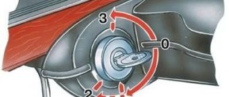
Ignition and starter switch (ignition switch)
The switch consists of an anti-theft mechanical lock and an electrical switch. The switch key has four positions:
II – the ignition and starter are turned on. Return to position I is automatic. The secondary activation of the starter is possible only after the key is turned to position 0.
III – the ignition is turned off and the anti-theft device is turned on when the key is removed.
To check the serviceability of the ignition switch, it is necessary to assemble the electrical circuit shown in Fig. 9.27.
Electrical diagram for checking the ignition switch:
When turning the key to position I (ignition on), lamps A and B should light up, and when turning the key to position II (ignition and starter on), lamps A and B should light up. In positions 0 and III, lamps should not light up. The voltage drop between terminals 30/1 and 15/1 should not exceed 0.25 V at a current of 20 A. A faulty switch must be replaced.
1. You will be able to download the book immediately after payment.
2. The book will be downloaded in PDF format, and you can download it to any device.
1. All books are of ideal quality, since we work with publishers directly.
2. Electronic books are in no way inferior to paper books and are their complete analogue.
3. Our company has offices in Ukraine, Russia and Poland, you can always contact us at a specific address.
4. All payments on the site are maximally protected and are made using global payment systems.
The book is not intended for sale in your country.
You can place an order for the paper version of this book on the website autoinform96.com.
Payment for goods and downloading of the book in electronic form (PDF format) is made on the website.
To do this, you need to find the book you are interested in and click on the “Buy” button. The price of the book is indicated on the button.
For convenience, the price on the website for residents of Russia, Belarus and Kazakhstan is presented in rubles.
After clicking on the “BUY” button, a payment window will open where you can select a payment system with which you can pay for the selected book using any bank card (Visa, MasterCard, MIR, etc.)
When you click on the “Pay by bank card” button, the Portmone payment system will open, which is the easiest way to make a payment.
In addition, the website offers four payment systems for payment:
Information for legal entities
The goods are paid for by bank transfer.
How to get an invoice?
You send us your company details by email, we issue an invoice and draw up an agreement. The contract is signed by both parties and after that the client pays the invoice.
How to pay the bill?
Payment by bank transfer to the company's bank account using the details specified in the invoice. All accounting documents are sent along with the goods. Deferred payment is possible (by agreement with management).
All products in our online store have an extended warranty of 6 months (electronics have an extended warranty of 3 months). The warranty card is sent to the buyer along with the spare part.
What it includes:
Guaranteed replacement of spare parts in case of defects within 6 months
If a manufacturing defect is detected, you can exchange the part under warranty within six months after purchase.
For this:
- You must send the part back to us.
- Immediately after receiving the auto parts, we carry out defect detection of the goods (3-10 days).
- If the defect confirms a manufacturing defect, we will send you a new spare part. Our company will cover the shipping costs for sending the replacement part to you.
- If the defect shows that the spare part was damaged as a result of improper use, we can repair it with your consent at your expense. If we refuse to repair, we will send the part back to you. In this case, the transportation costs for sending the part are borne by you.
repair parts
If a malfunction is detected, you can have the part repaired in our company.
For this:
- Send the part back to us.
- Immediately after receiving the auto parts, we carry out defect detection of the goods (3-10 days).
- After a defect, we can repair the spare part according to our price list with your consent. If we refuse to repair, we will send the part back to you. In this case, the transportation costs for sending the part are borne by you.
Our store service allows you to place an order very quickly and easily!
Consultation and product selection
If you don’t know exactly what auto part you need, you can get advice from our specialist by phone. To do this, leave a request for a free consultation using the button in the header of the site (a specialist will call you back within a few minutes), in addition, you can call the number indicated in the header of the site.
Placing and confirming an order
By going to the card of the selected product, you can place an order by clicking the “buy” button. Placing an order involves filling out the following fields: name, mobile phone number. To quickly order, you can use the call back form by clicking on the red circle with the handset and entering your phone number.
Attention! An incorrect telephone number, inaccurate or incomplete address may result in delays! Please check your personal information carefully when placing an order.
Within an hour after placing your order, our manager will contact you to agree on the order, timing, method and place of delivery.