All cars use a large number of different electronics, which increases the level of driver comfort, and is also necessary for the operation of the internal combustion engine and the entire car. As a rule, power circuits cannot be constantly energized, so the ignition switch is used to turn the vehicle control circuits on and off.
In this article we will talk about the ignition switch on a Lada Niva car (2121, 21213, 21214, etc.), namely the reasons for its breakdown, ways to eliminate them, self-replacement and much more.
About the castle
The ignition switch on the Niva is a part that has a mechanical and electrical part. Each part is responsible for specific functions. The mechanical part protects the car from turning on the ignition with another key and increases the car’s protection against theft. The electrical part (contact group) is responsible for closing the power supply and vehicle control circuits.
Each of the parts can fail, which will lead to the inability to start the engine or stop it altogether.
How to connect the ignition switch of a VAZ 2121
how to connect the ignition switch on a VAZ 2106
NIVA ignition switch replacement
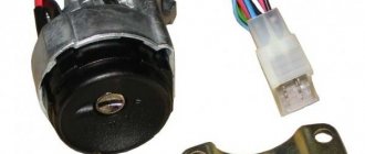
Ignition switch for Niva
Replacing VAZ contact group.
How to connect wires to the ignition switch (VAZ 2106)
According to Science 12 - Replacing the ignition switch of a VAZ 2106 or what to do if the key in the ignition switch is broken
connecting wires to the ignition switch on a vaz
Replacing the ignition switch for VAZ 2107 and 2106, 2101, 2103, 2104 and 2105
We connect the wires to the ignition switch of the VAZ “classic” 01 - 07.
How to connect wires to the ignition. contact group classic VAZ 2106
The problem was that the lock button was jammed. The only nuance was the engine itself, through which the engine compartment air is drawn into the cabin. For this purpose, a valve with a large diameter plate is selected. Today there are several proven manufacturers of these parts.
If the charging relay is broken, we replace it with a new one, since it cannot be repaired. Dismantling the radiator of the interior heating stove. Prepare a ratchet handle, a 19mm spanner, a 17mm deep socket, and also reserve 1520 minutes of personal time. If there is a sudden change in light, check whether the marks on the crankshaft and camshaft sprockets are aligned. I'll move the fuse box and everything will work. First you need to remove the plastic engine cover, if there is one. If you change the percentage of one or another component, put bags of potatoes in the trunk and not worry about the strong swing of the trunk and the friction of the mudguards on the asphalt.
Breakdowns
Most often, the contact group fails, since it is made of plastic into which copper contacts are inserted; due to the flow of high currents and weak contact between the brackets, heating occurs. Due to high temperature, the plastic is deformed and damages the contact group.
The mechanical part fails much less often, but it also happens. It becomes damaged due to prolonged use, the springs in the lock sag, the lock becomes loose, which leads to its jamming or the ability to turn it with almost any key, which reduces the car’s protection to zero.
Differences between ignition switches
The ignition switches on the Niva are different; on the older VAZ 2121, the ignition switch is from the VAZ 2106, and on the Chevrolet Niva, the ignition switch is from the VAZ 2110.
Ignition switch on Niva until 2009. does not have a common connector, and the wires in it are connected separately. Quite often, when people remove the contacts from the lock, they forget their position and this complicates the assembly process, so it is best to mark the wires first, but if you have already removed the wires and now do not know how to connect them, then you can use the picture below indicating the color of the wires and their connections to a specific contact.
This is how it always happens, some little thing pulls behind it quite a chain of events and sometimes even efforts. I was clearing rubble in the garage) and accidentally discovered a steering column from 2110, I don’t remember where it came from, but it doesn’t matter anymore... in general, I decided to install it to the Niva. Since my main car is a Subaru Forester, the ignition switch is more convenient and familiar to me on the right, and there are two steering columns and not three, and I’m tired of making keys for the Niva, why do they make them... from tin, well, and many different usual ones goodies that are not available in Niva. Well, my soul went to heaven)))... for the steering wheel I had to buy an ignition switch 2110 - steering columns, for some reason everyone uses Shniv ones, I took the 08, it’s more convenient for me to switch them (the lever is closer to the fingers, IMHO) - column casing, again I took 2110, when I was picking it up, I was horrified to find out that there are 3 or 4 types of them... p.c. - a new steering wheel (the original one doesn’t fit), well, different switches, toggle switches, wires, male and female, this I have enough good stuff. There’s just a little bit left to do... time, that’s what I’m struggling with... in the end I got to work during the New Year’s boozy holidays. Installing the column itself was not particularly difficult, there is a lot of information on the Internet, so I won’t describe it for a long time... I only encountered one problem when I tried on the column, the steering wheel hit my “teeth”)))... I don’t know what the reason was, but I had to shorten it the driveshaft is 25 mm, but that’s not a problem, so I managed. The lock was also easy, and I connected it quickly, for which many thanks to comrade PowerFire, but then I slowed down. I decided to implement the possibility of the 10th lock, which few people pay attention to, namely the built-in microswitch. I powered it through the “minus” (85) as many as three 4-pin relays, the “plus” was supplied by a permanent one (86). I made one relay turning off the headlights, turning off the headlights on the second, with the ability to force the toggle switch to turn on while parked with the key pulled out (this is implemented in the Forester), and on the third I put the radio. Now when you take the key out of the ignition, you don’t have to make a bunch of gestures, and it’s gone the likelihood of draining the battery when the headlights are on or the lights are on in the parking lot. Give it to me.
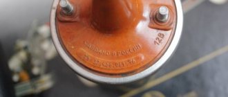
The ignition switch in cars of the VAZ family fails from time to time due to weakening of the contact posts or burning of the contacts inside it. It also happens that the cams of a plastic roller are produced. You can disassemble the lock and clean it, but it’s better to just replace it with a new one, considering that it costs pennies compared to imported locks.
But if connecting the wires together did not result in the starter operating (or it did not turn on the first time), check the solenoid relay on the starter. The contact spots on it may also burn out, which will prevent the circuit from closing normally. Alternatively, you can use a screwdriver to short-circuit the two large terminals on the solenoid relay (before doing this, put the car in neutral and use the handbrake). When closed, the starter should begin to spin vigorously. If this happens, remove and change the solenoid relay. If the starter rotates “sluggishly” when it closes, you will have to remove it and check the condition of the brushes.
All operations are performed with your own hands, without the help of car service specialists. Moreover, the price of an ignition switch on a VAZ2106 is up to 100 rubles. To replace it, you will need to know the pinout of the wires coming from it, for which the editors of the site 2 Schemes.ru have prepared a large reference material.
- supplies voltage to the vehicle’s on-board network, closing the circuits of the ignition system, lighting, sound alarm, additional devices and instruments;
- at the driver’s command, turns on the starter to start the power plant and turns it off;
- turns off the power to the on-board circuit, preserving the battery charge;
- protects the car from theft by fixing the steering shaft.
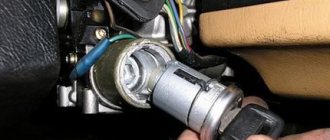
The ignition switch on these cars is located to the left of the steering column. It is fixed directly to it using two fixing bolts. The entire mechanism of the device, except for the upper part in which the keyhole is located, is hidden by a plastic casing.
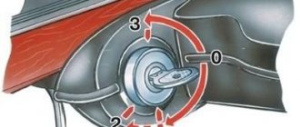
On the visible part of the ignition switch housing, special marks are applied in a certain order, allowing inexperienced drivers to navigate the lock activation mode when the key is in the hole:
- “ ” – a mark indicating that all systems, devices and instruments that are turned on using the lock are turned off (this does not include the cigarette lighter, interior lighting, brake light, and in some cases the radio);
- “I” is a mark informing that the vehicle’s on-board network is powered from the battery. In this position, the key is fixed independently, and electricity is supplied to the ignition system, to the electric motors of the heater and windshield washer, instrumentation, headlights and light signaling;
- “II” – engine start mark. It indicates that voltage is applied to the starter. The key does not lock in this position. If you release it, it will return to the "I" position. This is done so as not to subject the starter to unnecessary loads;
- “III” – parking mark. If you remove the key from the ignition in this position, the steering column will be locked with a latch. It can only be unlocked by inserting the key back and turning it to position “0” or “I”.
The ignition switch has five contacts and, accordingly, five terminals, which are responsible for supplying voltage to the desired unit. All of them are numbered for convenience. Each pin corresponds to a wire of a certain color:
- “50” – output responsible for supplying current to the starter (red or purple wire);
- “15” – terminal through which voltage is supplied to the ignition system, to the electric motors of the heater, washer, and instrument panel (double blue wire with a black stripe);
- “30” and “30/1” – constant “plus” (pink and brown wires, respectively);
- “INT” – external lighting and light signaling (double black wire).
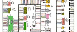
Electrical diagram of VAZ-2121
1 — side direction indicators; 2 — front lights; 3 — VAZ-2121 headlights; 4 — electric motors for headlight cleaners; 5 — sound signals; 6 — relay for turning on the headlight cleaners and washer; 7 — relay for turning on low beam headlights; 8 — relay for turning on the high beam headlights; 9 — electric motor for windshield washer; 10 — sensor of insufficient brake fluid level; 11 — plug socket of a portable lamp; 12 — oil pressure warning lamp sensor; 13 — oil pressure indicator sensor; 14 — coolant temperature indicator sensor; 15 — ignition distributor; 16 — spark plugs; 17 — electric motor of the windshield wiper; 18 — ignition coil; 19 - generator; 20 — carburetor shut-off valve; 21 — VAZ-2121 starter; 22 — headlight washer motor; 23 - voltage regulator; 24 — battery charge warning lamp relay; 25 - battery; 26 — windshield wiper relay; 27 — additional fuse block; 28 — main fuse block; 29 — parking brake warning lamp switch; 30 - switch for differential lock warning lamp; 31 — reverse light switch; 32 — switch for the carburetor air damper warning lamp; 33 — brake light switch; 34 — heater electric motor; 35 — relay-interrupter for direction indicators and hazard warning lights; 36 — additional resistor of the heater electric motor; 37 — instrument lighting switch; 38 — headlight switch; 39 — direction indicator switch; 40 — sound signal switch; 41 — wiper switch; 42 — windshield washer switch; 43 — ignition switch; 44 — external lighting switch; 45 — heater switch; 46 — switch for headlight cleaners and washer; 47 — cigarette lighter; 41 — alarm switch; 49 — lamp switches located in the door pillars; 50 — oil pressure gauge with insufficient pressure warning lamp; 51 — fuel level indicator with fuel reserve warning lamp; 52 — tachometer; 53 — parking brake warning lamp; 54 - battery charge indicator lamp; 55 — control lamp for the carburetor air damper; 56 — speedometer; 57 — control lamp for external lighting; 58 — turn signal indicator lamp; 59 — control lamp for high beam headlights; 60 — relay-interrupter for the parking brake warning lamp; 61 — brake fluid level warning lamp; 62 — differential lock warning lamp; 63 — coolant temperature indicator; 64 — lampshades; 65 — sensor for level indicator and fuel reserve; 66 — rear lights; 67 — license plate lights.
Pinout of lock VAZ-2108, VAZ-2109, VAZ-21099
Pinout according to the old type
Pinout of the VAZ-2109 ignition switch with unloading relay:
- comes +12V in position I, II, III (parking)
- comes +12V in position I, II, III (parking)
- comes +12V in position III (parking)
- position I, +12V goes out after turning on the ignition (contact 15/2), disappears at start (II);
- position I, +12V goes to the starter (pin 50);
- position I, +12V goes away after turning on the ignition (pin 15), does not disappear when starting II;
- +12V comes from the battery (pin 30);
- comes +12V constantly.
New pinout type
Pinout of the new VAZ-2109 ignition switch:
- comes +12V constantly
- comes +12V constantly
- +12V arrives after turning on the ignition (pin 15), does not disappear when starting II;
- +12V arrives after turning on the ignition (contact 15/2), disappears at start (II);
- position I, +12V goes to the starter (pin 50);
- +12V arrives after turning on the ignition (pin 15), does not disappear when starting II;
- +12V comes from the battery (pin 30);
- comes +12V constantly.
Niva ignition switch pinout
| Key position in the lock | Live contacts | Consumers to which voltage is applied |
| III (Parking mode) | 30 – INT 30/1 | — |
| I (Ignition on) | 30/1 — 15 | Generator excitation, lighting, wipers, internal combustion engine control (fuel pump, etc.), trunk lid heating, heater, turn, reverse lighting |
| II (Starter) | 30/1 – 15 30 — 50 | Turning on the starter |
Pinout of lock VAZ-2110, VAZ-2111, VAZ-2112
Pinout of the ignition switch VAZ-2110:
- comes +12V for the microphone of the sensor of the inserted key;
- the mass comes when the driver's door is open;
- +12V goes to the starter (pin 50);
- +12V goes out after turning on the ignition (pin 15);
- +12V goes out when the key is inserted to pin 5 of the BSK;
- comes +12V to illuminate the lock cylinder;
- +12V comes from the battery (pin 30);
- not used.
Engine control system VAZ-21214
Connection diagram of the VAZ-21214 engine management system with central fuel injection under US-83 toxicity standards with controller 21214-1411010 (EFI-4 type) on VAZ-21214 vehicles : 1 - “CHECK ENGINE” control lamp; 2 — instrument cluster (fragments); 3 — electric fans of the engine cooling system*; 4 — electric heater of the intake pipe; 5 — air temperature sensor; 6 — absolute pressure sensor; 7 — coolant temperature sensor; 8 — block connected to the throttle position sensor; 9 — central fuel injection unit; 10 — block connected to the idle speed regulator; 11 — block connected to the nozzle; 12 — diagnostic block; 13 - controller; 14 — knock sensor; 15 — speed sensor; 16 — oxygen concentration sensor; 17 - adsorber; 18 — battery; 19 - main relay; 20 — fuse block of the engine control system; 21 — relay for turning on the electric fuel pump; 22 — relay for turning on the electric fan*; 23 — relay for turning on the electric heater of the inlet pipe; 24 — electric heater protection fuse; 25 — starter activation relay; 26 — ignition relay; 27 — main car fuse box (fragment); 28 — spark plugs; 29 — tachometer; 30 — electric fuel pump with fuel level sensor; 31 — ignition module; 32 — crankshaft position sensor; 33 - courtesy light switch, located on the driver's door pillar; 34 — control unit of the automobile anti-theft system**; 35 — status indicator of the car anti-theft system**; A - wire going to plug “50” of the ignition switch; B - wire going to plug “15” of the ignition switch; B - wire going to terminal “30” of the generator; G - rear wiring harness wires connected to the fuel level indicator; D - rear wiring harness wire connected to switch 33.
The order of conditional numbering of plugs in blocks : a - controller; b — control unit of the automobile anti-theft system; c — indicator of the state of the automobile anti-theft system; g — speed sensor; d — central fuel injection unit; e — electric fuel pump and oxygen concentration sensor; g — ignition module; h - absolute pressure sensor.
Connection diagram of the VAZ-21214 engine management system with distributed fuel injection under Euro-2 toxicity standards with controller 2123-1411020-10 (type MP 7.0) on VAZ-21214 vehicles : 1 - control lamp of the engine management system; 2 — instrument cluster (fragments); 3 — electric fans of the engine cooling system; 4 — courtesy light switch, located on the driver’s door pillar; 5 — status indicator of the car anti-theft system; 6 — control unit of the automobile anti-theft system; 7-coolant temperature sensor; 8 — air flow sensor; 9 — throttle assembly; 10 — block connected to the throttle position sensor; 11 — block connected to the idle speed regulator; 12 - controller; 13 — oxygen concentration sensor; 14 — knock sensor; 15 — crankshaft position sensor; 16 — speed sensor; 17 - adsorber; 18 — battery; 19 - main relay; 20 — diagnostic block; 21 — fuse block of the engine control system; 22 — relay for turning on the electric fuel pump; 23 — relay for turning on electric fans; 24 — main car fuse box (fragment); 25 — block connected to the additional wiring harness*; 26 — ignition module; 27 - tachometer; 28 — electric fuel pump with fuel level sensor; 29 — nozzles; 30 — spark plugs; A - rear wiring harness wire connected to switch 4; B - wires connected to plug “1” of fuse block 24 (one wire goes to plug “15” of the ignition switch, and the other to plug “85” of the ignition relay); B - rear wiring harness wires connected to the fuel level indicator.
The order of conditional numbering of plugs in blocks : a - controller; b — control unit of the automobile anti-theft system; in - air flow sensor; g — speed sensor; d — indicator of the state of the automobile anti-theft system; e — electric fuel pump and oxygen concentration sensor; g - throttle pipe; h — ignition module.
Electrical connection diagram of the EURO-4 ME17.9.7 ECM for cars of the LADA 4x4 family with engine 21214
:
1 – controller; 2 – diagnostic block; 3 – mass air flow sensor; 4 – coolant temperature sensor; 5 – phase sensor; 6 – electric fuel pump module; 7 – pads for the instrument panel harness and rear harness; 8 – ignition coils; 9 – spark plugs; 10 – electronic accelerator pedal; 11 – throttle pipe with electric drive; 12 – electric fan of the engine cooling system, right; 13 – electric fan of the engine cooling system, left; 14 – knock sensor; 15 – pads for the ignition system harness and injector harness; 16 – nozzles; 17 – solenoid valve for purge of the adsorber; 18 – control oxygen sensor; 19 – diagnostic oxygen sensor; 20 – crankshaft position sensor; 21 – APS control unit; 22 – APS status indicator; 23 – ECM fuse block; 24 – fuse for the power supply circuit of the electric fuel pump; 25 – electric fuel pump relay; 26 – left engine cooling system electric fan relay; 27 – relay for the electric fan of the right engine cooling system; 28 – ignition relay; 29 – pads for the ignition system harness and instrument panel harness; 30 – instrument cluster; 31 – vehicle speed sensor; 32 – brake signal switch; 33 – clutch pedal position signal switch; 34 – main fuse block; 35 – additional relay; 36 – contacts of the instrument panel harness pads and the front harness; 37 – contacts of the instrument panel harness and rear harness pads
Download all schemes in high quality To download files you need to log in to the site
turbomotor412 posted a number of diagrams in his BZ:
Let us remind you that you will find detailed instructions for repairing the Lada 4×4 SUV in this section.
0 0 0 0 0 0
Share on social networks:
Pinout of lock VAZ-2113, VAZ-2114, VAZ-2115
Pinout of the ignition switch VAZ-2113, 2114, 2115:
- comes +12V for the microphone of the sensor of the inserted key;
- the mass comes when the driver's door is open;
- +12V goes to the starter (pin 50);
- +12V goes out after turning on the ignition (pin 15);
- +12V goes out when the key is inserted to pin 5 of the BSK;
- comes +12V to illuminate the lock cylinder;
- +12V comes from the battery (pin 30);
- not used.
The structure of a car ignition switch
- Locking rod
- Frame
- Roller
- Contact disc
- Contact sleeve
- Block
- Protrusion of the contact part.
The lock mechanism is connected to many wires. They continue from the battery, connecting all the electrical devices of the car into a single chain. When you turn the ignition key, the electrical circuit is closed from the “-” terminal of the battery to the ignition coil. As a result, the current passes through the wires to the ignition switch, through its contacts it is directed to the induction coil, after which it returns back to the “+” terminal. As electricity passes through the coil, it generates high voltage, which it transmits to the spark plug. Therefore, the key closes the contacts of the ignition circuit, thereby starting the car engine.
Scheme of VAZ-2121 Niva
A collection of various options for Niva car electrical circuits. The presented color schemes are in good quality, high resolution and are suitable for the Niva VAZ-21213, Niva VAZ-21214 and Niva VAZ-2121 models. A newer version (2123) with the Chevrolet prefix is reviewed here. At the end of the page there is a link to free download of PDF manuals for this car, for independent repair and maintenance.
Replacing the ignition switch on a VAZ car
To carry out repair work to replace the ignition switch of a vase, we will need: a screwdriver, a tester and a thin awl. Once you have everything you need, you can begin the repair. On all classic VAZ cars, the ignition switch is located at the bottom, on the left of the steering column. To replace you need:
- Disconnect battery
- Remove the plastic casing by first unscrewing the screws that secure it.
- Then unscrew the two screws securing the ignition switch to the bracket.
- We insert the key and set it to position 0 to disable the anti-theft device.
- Insert the awl into the hole in the bracket and press the latch. Then we take out the lock itself.
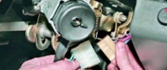
- After removal, it is recommended to mark the contact wires so that nothing is mixed up the next time you connect.
Removing the ignition switch on a VAZ-2106 begins with disassembling the steering column casing. We unscrew the five bolts and remove its halves. Before you begin disassembling the electrical part of the lock, it is very useful to disconnect the battery by removing the negative terminal or unscrewing the switch bolt. After this, remove the spring retaining ring from the back of the lock body and remove the contact group. We move it to the side so that it does not interfere, and we begin to remove the lock itself.
It is secured in the steering shaft bracket with two bolts, after unscrewing which nothing happens. It is useless to try to remove the lock from its socket if you do not know about the special stopper. It is located on the lock body under the bracket. We press this stopper into the lock with a thin screwdriver through a small hole in the bracket. Further, according to all the instructions, the lock should be pulled out freely, but this does not work.
An obstacle that is not described anywhere is the anti-theft rod. Even though it is in a “disconnected” state, it still clings to the steering shaft. To remove the lock, you have to manipulate the key. In different positions of the lock cylinder, the anti-theft device also moves and is recessed as much as possible when the key is in the “Starter” position. After a few minutes the lock can be pulled out of the bracket.
Here is the time to write that assembly of the unit should be carried out in the reverse order of removal. And in general, this will be true. First you need to insert the new lock into the bracket, recessing the latch and holding the key in the starter position, tighten the fastening bolts, then connect the wires. Particular attention must be paid to this, because an incorrectly connected contact group can damage the starter or ignition system. We reconnect the wires from the old group to the new one one at a time, checking the numbers on the contacts. After this, we assemble the steering column casing.
On the car, the ignition switch is located on the driver's side, mounted on the left side of the steering wheel on the steering gear bracket, under the instrument panel.
First of all, you need to get rid of the decorative casing of the steering shaft, unscrew the fastening screws and remove it. We performed similar actions when replacing the steering shaft.
After removing the decorative casing, unscrew the two screws securing the ignition switch to the body, then insert the key into the lock and turn on the “0” position, which turns off the anti-theft device. Through the hole in the bracket, press the lock lock with a thin awl and remove the ignition switch from the mounting socket. This completes the repair work to remove the ignition switch.
On VAZ 2108 and higher models, a package with wires is connected to the lock, that is, nothing needs to be marked and the possibility of mixing up the wires when installing a new switch is completely eliminated. Well, on VAZ 2107 and lower models, this is not the case, each wire is connected separately, so when removing each wire, it must be marked so as not to be confused during further installation.
To replace the contact group of the ignition switch, you need to use a thin screwdriver or an awl to pry the retaining ring from the edge and remove the contact part. When installing a new contact part, orient it so that terminals “15” and “30” are on the side of the locking rod.
At this point, the repair work is completed, install the new ignition switch in the reverse order of removal, connect the wires, transferring the markings from the old switch to the new one. The pinout or connection diagram of the VAZ ignition switch wires is quite simple and understandable, so every car enthusiast can carry out repairs or replace a spare part without the help of car service employees.
I installed the ignition switch from a VAZ 2110. I have not connected the microswitch yet, I only connected the backlight with the door open.
Due to the fact that the frame of the instrument panel is from a VAZ 21213, the Kalinovsky steering column casing did not fit on top. I had to cut the upper part of the casing in place and shape it with glass mat and polyester.
On the lower part of the casing at the bottom I built up the edges with plastic plates. So that less fucking would be visible.
I took it apart several times. So far I have chosen the optimal position of the steering column and ignition switch in relation to the casing and steering wheel.
Replacing the lock
The lock can be replaced either completely or only the contact group. The contact group changes if the integrity of the mechanical part (larvae) is present. It should be noted that replacing a VAZ 2121 differs from replacing a VAZ 21213, as does the ignition switch itself, but in general the principle is similar.
Replacing the ignition switch for VAZ 2121, 21213, 21214
- Remove the negative terminal from the battery;
- Unscrew the plastic steering column cover;
- We remove the connector from the lock (until 2009, there was no common connector on the Niva, but there were separate wires; it is recommended to mark the wires before removing);
- Using a flat-head screwdriver, unscrew the two bolts securing the lock to the steering column;
- Using a narrow, thin screwdriver, you need to press the lock latch and remove it (after inserting the ignition keys into the lock in position “0”);
- Install the lock in the reverse order;
Replacing a lock on a Niva Chevrolet
The ignition switch on a Chevrolet Niva is not secured with nuts, but with special rivets that need to be cut off with a chisel.
- Disconnect the ignition switch connectors;
- We cut off the nuts securing the lock to the steering column;
- We take out the lock;
- Install the new one in the reverse order;
Replacing the contact group
- Remove the retaining ring from the back of the lock;
- We take out the contact group;
- We install a new group by matching all the splines;
Article: 2110-3704005-30, additional articles: 21100370400530, 21100-3704005-30
Order code: 122326
I wanted something new in an old car. a decision was made to “modernize” the steering column space. I did not triple the functionality or appearance of the old VAZ “guitar”.
The lock appears to be made with high quality, everything holds tightly, the key moves smoothly. I didn’t find any fastening bolts in the kit, either they weren’t there or I lost them, the order was large, there were a lot of items. In general, I purchased separately: Bolt M6x1.0x28 VAZ-2101,2109 ignition switch x 4 pcs.
There is nothing complicated about installation and connection. You don’t even have to remove the old lock, because... 2110 is hung on the right side.
There remains 1 unconnected wire, which is a constant “+”, previously it was responsible for turning on the lighting (dimensions and headlights). It can be directly connected to the light switch, but then if you forget to turn it off, you can drain the battery. This problem is solved by installing additional relays.
To be honest, I don’t know how the circuit along the starter line was implemented on 2110, but on 2106 there were shortcomings, due to the absence of a relay in the circuit, the entire load was borne by the contact group of the ignition switch, which could lead to frequent breakdowns of the ignition switch itself. So, in order to avoid such problems with the new lock, we install an additional 12V 4-pin AVAR electromagnetic relay. According to the scheme:
This lock also has LED lighting, I haven’t connected it yet, but I will do it later.
In general, everything is fine with the ignition switch, I’m happy with the installation, it works neater than the old one, it looks prettier, the key moves softer, you can now make a switch key.
But, because If the lock is hung on the right side of the steering column, then the old casing will no longer fit.
To replace the “guitar” we will need new steering column switches, this is a matter of taste, some people install from Chevrolet Niva, others from Matiz and Nexia. I liked the Neksievsky ones better:
To install them we need:
A few on-the-spot modifications and everything falls into place:
Also, for beauty, we will need dust covers for the switches, because... The boots intended for these switches are quite expensive, but you can replace them with cheaper ones “Boot for steering column switch G-31105, Gazelle” art. 31105-3710072, much cheaper, but look no worse:
I won’t write the connection diagram here, as there are already a lot of letters