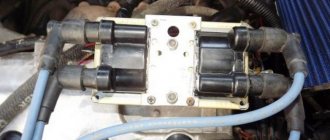
Connection diagram of the ignition switch to the electrical wiring of a VAZ-2114 car
In the technical documentation for the VAZ-2114 there is a separate section that specifically describes the design of the vehicle’s electrical equipment. So, all the elements are described in full. But, in this particular case, the issue of independently connecting the ignition wires will be considered.
So, let's look at the diagram to see how the contact connections of the ignition switch are connected.
Ignition switch pinout diagram
Regardless of the ignition being turned on, the following devices can operate: high beam, interior and instrument panel lighting, hazard lights, brake light, sound signal, as well as exterior lighting.
A separate item worth highlighting is additional equipment: a car radio (of any format), speakers, additional lighting devices are powered directly into the battery or on-board network, and much more.
Ignition switch device
Next, we will consider the switched circuits of various key positions in the ignition switch:
| Key position | Live contacts | Switched circuits |
| 0 (Disabled) | 30 | _ |
| 1 (Ignition) | 30-15 | Ignition system, generator excitation, headlights, turn signal, control devices, windshield and headlight cleaners and washers, heater fan motor, rear window defroster, cigarette lighter |
| II (Starter) | 30-15 | See Regulation I |
| 30-50 | Starter |
Ignition switch pinout
Product selection
There are several options for the ignition switch on the VAZ-2114. Let's look at each one separately:
- 2110-3704005 or KZ-881 – original catalog numbers of the ignition switch manufactured by AvtoVAZ. The wiring diagram is standard, that is, factory. Installation is quite easy. The average cost is 1000 rubles .
Pinout of lock VAZ-2108, VAZ-2109, VAZ-21099
Pinout according to the old type
- Installation on VAZ 2108 and 2109 with a low torpedo instrument cluster from 2115
Pinout of the VAZ-2109 ignition switch with unloading relay:
- comes +12V in position I, II, III (parking)
- comes +12V in position I, II, III (parking)
- comes +12V in position III (parking)
- position I, +12V goes out after turning on the ignition (contact 15/2), disappears at start (II);
- position I, +12V goes to the starter (pin 50);
- position I, +12V goes away after turning on the ignition (pin 15), does not disappear when starting II;
- +12V comes from the battery (pin 30);
- comes +12V constantly.
New pinout type
Pinout of the new VAZ-2109 ignition switch:
- comes +12V constantly
- comes +12V constantly
- +12V arrives after turning on the ignition (pin 15), does not disappear when starting II;
- +12V arrives after turning on the ignition (contact 15/2), disappears at start (II);
- position I, +12V goes to the starter (pin 50);
- +12V arrives after turning on the ignition (pin 15), does not disappear when starting II;
- +12V comes from the battery (pin 30);
- comes +12V constantly.
conclusions
The pinout or connection diagram of the VAZ-2114 ignition switch wires is quite simple and understandable, so every car enthusiast can carry out repairs or replace a spare part without resorting to the help of car service employees.
Sometimes during repairs or replacements you have to disconnect the ignition switch from the on-board network and then reconnect it. This seemingly simple operation is fraught with many features, without knowing which you can make serious mistakes. Today we will look at what the VAZ 2114 ignition switch circuit looks like, how to connect this device according to it, and also what important points should be taken into account.
Ignition switch VAZ 2114
Settings
Only autorun functions can be configured. To activate programming mode:
- Disable security
- The ignition key is set to position 0.
- Then press the Valet key six times in the main block.
- Turn on the ignition
- After six beeps, use the same key to select the desired function, and use the key on the key fob to select the desired value.
The optimal settings for VAZ - 2115.2114 will be the following: function 12 - set to value 3, function 11 - value 4, function 9 - value 3. To select value 4, press and hold the third button until the melody is played. After playing, press it again.
To check the correct connections, perform the following steps:
- Disconnect the yellow cord from block A91 to terminal 15 for a while.
- The engine is started using the ignition key
At the same time, the alarm indicator should blink.
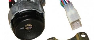
Purpose and principle of operation
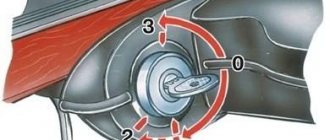
The ignition switch is an electrical device responsible for both starting the engine and turning on the power in the on-board network. It has 3 different sector switch positions controlled by the ignition key.
Each of them is responsible for its own separate function, namely:
- Position “Off 0” - power is supplied to contacts 30 - all equipment is turned off.
- Position “Ignition 1” - power is supplied to contacts 30-15 - current goes to the ignition system, instruments, headlights, windshield wipers, stove, cigarette lighter, glass heater, turn signals.
- Position “Starter 2” - power is supplied to contacts 30-15 and 30-50 - all the same circuits are energized as in position “1”, as well as the starter.
It is worth noting that the car has a number of electrical circuits that can be turned on regardless of the position of the key, namely: interior lighting, hazard warning lights, high beams, brake light and horn.
In turn, the pinout of the VAZ 2114 ignition switch looks like this (the legs of the lock connector are indicated):
- 1 - +12 volts for the key sensor;
- 2 - to ground (if the driver's door is open);
- 3 - +12 volts to the starter (aka contact 50);
- 4 - +12 volts with the ignition on (aka - pin 15);
- 5 - +12 volts with the key inside the lock;
- 6 - +12 volts for lock illumination;
- 7 - +12 volts from the battery (aka - pin 30);
- 8 - not applicable.
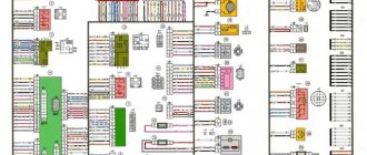
The VAZ 2114 ignition circuit, according to which the lock is connected to the on-board network in accordance with the pinout presented above, looks like this:
Electrical circuit design of VAZ 2115
The VAZ wiring diagram is a single-wire circuit, which supplies the positive pole from the battery to the remaining elements of the circuit, and the negative pole is the housing.
The electrical circuit of the VAZ is protected from current surges in the form of fuses with fuse links. They were placed under the hood.
Fuses provide reliable protection for such expensive equipment as:
- the circuit in which the ignition switch is included;
- battery charging circuit;
- generator circuit and starter.
The VAZ electrical circuit includes relays that connect:
- headlight cleaners;
- emergency alarm;
- direction indicators;
- windshield cleaners;
- monitoring the serviceability of light bulbs;
- electric lifts;
- electric heated rear windows;
- horn;
- driving lights;
- low beam headlights.
The VAZ wiring diagram is made with wires of a certain color, which are designated by letters. A wiring harness of a certain color is secured with blocks.
The injection engine is controlled by a system that consists of a control unit - ECU - and sensors. The control unit occupies a central place in the fuel supply system. It has a second name - controller. It processes information received from sensors and controls systems that neutralize the toxicity of waste products and the performance of the machine.
There is a constant relationship between these elements - the controller and the sensors, which ensures uninterrupted operation of the drive.
The VAZ wiring diagram includes sensors with the following functions:
- fixing the position of the crankshaft: interacting with the ECU, it allows the car to move;
By studying their operation, you can avoid the troubles caused by faulty sensors.
Thus, the VAZ electrical circuit made it possible to create a reliable and interesting car. You can maintain it and maintain it in working order yourself, using the diagrams.
Basic malfunctions of the ignition switch and their elimination
The most common reasons why a car owner has to replace the ignition switch include:
- loss of a key (and lack of a spare one);
- mechanical damage (including a piece of key getting stuck in the lock);
- burning of the lock contact group.
If the first two problems can be established without additional diagnostics, then you can find out whether the entire ignition switch is externally working only by carrying out a small check. You will need any multifunction tester (multimeter) for this.
Checking the ignition switch
It is performed as follows:
- Set the device to ohmmeter mode.
- Remove the column casing.
- Disconnect the block with wires from the lock.
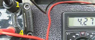
- Find pins 7 and 4 on the lock connector.
- Connect the probes to them, and then turn the key in the lock (setting it to the “Ignition” mode).
- Find pins 7 and 3 and connect the probes to them.
- Turn the key, setting it to the “Engine Start” mode.
If the ignition switch is fully operational, then in both cases the ohmmeter will show no resistance (otherwise it can be concluded that the lock is faulty).
Troubleshooting Methods
There are two methods for detecting faults:
- Visual;
- Diagnostic.
We suggest studying a visual method for determining a malfunction or breakdown of the contact elements of the ignition switch using the table.
| Action | The device is working properly | The device is faulty |
| Turn the key to the right position (ignition) | All electrical equipment turns on | All or part of the electrical equipment does not work |
| Turn the key to the second position | The starter is spinning | The starter does not work, the traction relay does not click under the hood |
But diagnostics allows you to get a more detailed answer. In addition, a visual inspection will not give you the opportunity to find all the reasons that could cause the ignition switch to break down.
To work, you will need a mini-tester and a multimeter in ohmmeter mode:
- Disconnect the power supply from the ignition switch. To do this, you need to remove the skin from the steering column;
- Switch your multimeter to an ohmmeter;
- On the block coming from the lock you need to find pins 7 and 4, which correspond to pins 15 and 30;
- Connect the multimeter probes to them;
- Turn the key to the “Ignition” position;
- On the block, find pins 7 and 3, corresponding to 50 and 30. Also connect a multimeter to them;
- Turn the key to the second position - Start the engine;
- If serviceability is present, the device will show zero resistance in both test cases.
Replacing the lock
If after diagnostics it turns out that the lock has stopped working normally, it should be replaced with a new, similar one. This is quite simple to do, but before doing this, for greater convenience, it is recommended to remove the steering column casing and switches.
You can do this as follows:
- Disconnect the negative terminal from the battery.
- Unscrew the 3 fastening screws of the casing halves.
- Unscrew the self-tapping screw that connects the housing to the switches.
- Unscrew the 2 screws holding the housing to the column.
- Pull down the latch holding the column.
- Lower the steering wheel down.
- Remove the lower casing.
- Disconnect the power supply from the alarm system.
- Remove the top casing.
- Simultaneously press the latches holding the steering column switches.
- Remove the switches by disconnecting them from the block with wires.
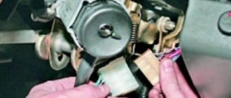
Preparing to remove the ignition switch
The removal of the lock itself is carried out as follows:
- Disconnect the wires suitable for the lock from its connector (remember that the terminals from the battery must remain removed, otherwise there is a risk that the ignition system of the VAZ 2114 injector 8 valves will receive additional damage as a result of a short circuit).
- Using a hammer and chisel, loosen and slightly turn (preferably several turns) the anti-theft shear bolts.
- Unscrew the bolts using pliers.
- Remove the bracket from the steering column.
- Remove the ignition switch.
Removing the ignition switch
Installing a new lock is carried out in exactly the same way, but in the reverse order. In this case, standard 20 mm fastening bolts with M6 thread can be used as bolts.
It is worth noting that the use of “ordinary” bolts can play into the hands of car thieves, because unscrewing them is much easier than special fasteners. That is why it is recommended to use tear-off bolts, which can be purchased both online and to order in auto stores.
After the new lock is installed, all that remains is to test it in action, simultaneously testing the performance of the on-board electronics in different key positions.
Steering lock testing
Testing the steering wheel
If you do not check the operation of the steering wheel lock, you may encounter certain problems in the future. Therefore, do not waste your time on this event. It consists of removing the key from the ignition and turning the steering wheel at a slight angle.
- If there is no lock, you will need to slightly adjust the position of the lock. Make sure it fits into the groove located on the steering shaft.
- If the locking is effective, you will only need to tighten the four installed breakaway bolts until they stop. Twist until the heads break.
It is worth noting one very important nuance. Some people don't find it necessary to use breakaway bolts. Instead, the most common fixing bolts with a length of 20 millimeters and an M6 thread are used. On the one hand, this will make it easier to remove the device in the future, if such an event is required again. On the other hand, in the absence of a reliable anti-theft system, voluntarily giving attackers access to your car is not the best idea.
When the lock installation is completed and the test has passed, do not forget to connect the device to power and start the engine. If it starts, all systems dependent on the ignition switch are working, you can fully begin reassembly. Follow the reverse instructions for removing the casing and steering column switches. It would not be amiss to check the condition of certain nodes along the way. It is quite possible that some of them also need replacement or a little preventive maintenance.
Source
Useful video
You can find more information on this issue by watching the video below:
Thanks to the ignition switch (ISL), the car is not only started, but also the lighting system is turned on and power is supplied to the components included in the on-board network circuit. The article discusses when the ignition switch needs to be changed on a VAZ 2114 car, and instructions are given for replacing it.
Preparation
It is necessary to prepare spare parts and other equipment for work. A new ignition switch will be needed. It is quite easy to find original parts and analogues on the Internet, but it is worth considering that it is advisable to purchase the lock “assembled”.
Catalog number of the original VAZ 2114 ignition switch: 21103704010. Approximate price: 500 rubles for a used part and 1200 for a new one.
As a replacement, you can use analogues with numbers: 09401, 24370407. Approximate price: 1000 rubles (new part).
In addition to the lock itself, you will need the following tools:
- spanners;
- chisel;
- pliers;
- screwdriver.
Before you begin, you must also remove the steering column cover and steering column switches.
In what cases is replacement required?
There are several situations when replacement of the seal is necessary:
- malfunction of the unit itself;
- loss of keys;
- mechanical damage to the protection during theft;
- contact group malfunction.
3Z device diagram
A unit malfunction can be detected when the engine starts. When the starter does not spin, the solenoid relay does not click, and electrical equipment does not work. Failures can be mechanical or electrical.
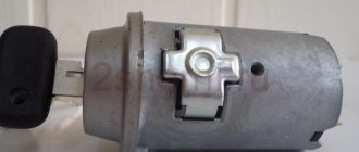
Principle of operation
The lock works as follows. When the key is placed in the hole, its locking mechanism is deactivated. This happens due to the reverse movement of a special rod.
By turning the key to the first position, you will power the “15” and “30” contacts. This will alert (but not enable) the following items:
- ignition system;
- headlight bulbs;
- external light alarm;
- electrical equipment of the dashboard;
- windshield wipers and washer;
- cigarette lighter;
- rear window defroster;
- generator excitation winding.
If in a VAZ-2114 car the ignition switch is moved to the second position, in addition to the listed equipment, the starter will start. As you can see, a lot depends on the serviceability of the device in question. What are the symptoms of a failed ignition switch? Let's start with the fact that its malfunction can be either mechanical or electrical in nature. In the first case it is:
- lock jamming in one of the positions;
- inability to unlock the steering shaft;
- turning on the ignition with a non-original key or other object.
If the lock has an electrical problem, you may notice the following symptoms:
- the warning lights on the instrument panel do not light up or light up and go out periodically;
- the starter does not start;
- Some or all electrical appliances, the circuit of which is powered through the ignition switch, do not work (cigarette lighter, headlights, washer, wipers, etc.).
How to determine the malfunction?
A faulty unit can be detected either by visual inspection or by diagnostics.
The visual method is to check the behavior of the machine at different key positions. First, the key is set to the right position - “ignition”. If the unit is working properly, then all electrical equipment works. If there are any problems with the electrical system, either all or part of the electrical equipment does not work.
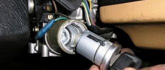
Turning the key in the lock
In the second position of the key, the starter should start. If it does not spin and you cannot hear the click of the retractor relay under the hood, then it is possible that either the starter or the starter is faulty. More specific information can be obtained using diagnostics. This is done with a multimeter set to ohmmeter mode. To carry out diagnostics, you need to remove the steering column cover.
Next you need to do the following:
- Disconnect power from the 3Z.
- Next, find pins 4 and 7 coming from the node. They correspond to pins “30” and “15”, and connect the multimeter terminals to them.
- Then the key in the 3Z turns to the first position. If the unit is working properly, the resistance should be zero.
- Then the operation of the unit is checked when the key is turned to position II. Likewise, the multimeter should show zero resistance if the circuit breaker is working properly.
Once you are convinced that the protection device is faulty, it must be replaced (the author of the video is Region 4253).
Connecting autorun
The VAZ-2114 models use an ignition switch with three terminals - 15 (blue wire), 30 (lilac) and 50 (red). Terminal 30 is connected to the battery. When you turn the key, blue wire 15 is connected to this terminal. The third terminal is responsible for the starter.
As it is written in the instructions, it is quite possible to power the alarm from contact 30, from which the lead is made. And the cable from connector X1, yellow, is connected to connector 15.
After all the actions taken, the connection of the tachometer remains. In this case, a loop antenna and a reading device are combined. Connector X3 has a gray-black outgoing wire. It is connected to the tachometer as shown in the VAZ dashboard diagram:
This will allow the alarm to control the speed. And at the very end we connect the ground from the main unit. This is a black cord from connector X3.
Instructions for replacing the ZZ
Replacing the ignition switch on a VAZ 2114 injector takes place in stages. At each stage certain actions are performed.
Preparation
First of all, you should prepare for the replacement procedure by preparing an electrical circuit diagram and the necessary materials and tools:
- new node;
- 4 assembly mounting screws;
- chisel;
- a set of keys;
- Phillips screwdriver;
- hammer;
- pliers.
The VAZ 2114 ignition switch should be purchased assembled.
For ease of operation, remove the cover from the steering column and switches.
Dismantling the casing is carried out step by step:
- First of all, the car is de-energized by disconnecting the negative terminal from the battery.
- Use a Phillips screwdriver to unscrew the screws securing the casing.
- Then the self-tapping screw is unscrewed, with which the housing is secured.
- Now you need to remove the screws holding the lower part of the housing to the steering column.
- At the next stage, the lever is lowered down, with the help of which the steering column is fixed at the angle, and the steering wheel.
- Next, the lower casing is dismantled.
- After disconnecting the power supply, you can remove the upper part of the casing.
- To remove the steering column switches, press the locking elements and remove the elements from their standard places.
- The switches should also be disconnected from the power supply.
Removing a faulty device
Having opened access to the protection zone, you can dismantle it. The difficulty of dismantling is that there are no heads on the 4 bolts that secure the ignition switch to the steering column on the VAZ 2114. The absence of heads prevents criminals from stealing a car without a key.
Dismantling with hammer and chisel
Dismantling of the protection zone is carried out as follows:
- you need to loosen the bolts using a hammer and chisel;
- then the loosened bolts are removed with pliers;
- then the bracket is removed from the steering column;
- the power supply is turned off;
- Now you can dismantle the unit.
The node connection diagram is simple. If it is purchased assembled, then it is not difficult to understand the diagram in order to connect the wires correctly.
Installing a new lock
The procedure for installing the ignition switch on a VAZ consists of the following steps:
- first you need to install the key in the new unit in position “I”, then the latch, thanks to which the steering wheel is locked, will hide;
- then the protection is mounted and the actions are performed in the reverse order of removal;
- After tightening the 4 bolts, you need to tighten them a little.
After installing the new unit, you need to check the steering lock. To do this, remove the key from the lock and turn the steering wheel to a small angle. If the steering wheel does not lock, you must install the unit correctly: the latch must fit into the groove located on the steering column. If the locking function works, all you have to do is tighten all the breakaway bolts until they stop. You need to tighten them until the heads are broken.
When replacing the VAZ ignition switch is completed, you need to connect the power and check the functionality of the device by starting the engine.
Installing a new device
Now you can finally proceed directly to replacing the broken or worn out ignition switch on your VAZ2114 car.
Removing the ignition switch
To do this, follow the following sequence of actions:
- Insert the key into the new lock and turn it to the first position. This will allow the latch, which is responsible for locking the steering shaft, to hide inside the housing structure;
- Insert the lock into place following the reverse dismantling sequence;
- Install the four retaining bolts and tighten them slightly.
How to set the ignition yourself?
Precise ignition adjustment on the VAZ 2115 injector is performed using a special strobe light. If this is not possible, you can set the ignition on the VAZ by spark.
To do this, follow these steps:
- First of all, the engine is warmed up until it reaches operating temperature.
- The distributor does not need to be removed, but only relaxed.
- You need to remove the central wire from the distributor.
- The piston in the 1st cylinder must be at TDC (the marks are set differently on 8 and 16 valve engines).
- Now you need to hold the short-circuit wire with your left hand and turn on the ignition.
- Use your right hand to adjust the distributor counterclockwise, while keeping the high-voltage wires above the metal.
- Then similar actions are performed, turning the distributor clockwise until a spark appears.
- At this point, the alignment ends, and the distributor is fixed in its regular place.
With the ignition set correctly, the car will operate without interruption with optimal fuel consumption and maximum power.
Step-by-step replacement of the ignition relay
If during the inspection it turns out that the ignition switch relay has failed, then experts do not recommend repairing this element, as was previously said. To buy a new relay, minimal cash costs will be required, and every car enthusiast can make a replacement if all operations are carried out in stages:
- The most important thing to do first is to disconnect the battery from the power supply; to do this, simply disconnect the negative terminal from the battery.
- When using a screwdriver, it is best to use a slotted tool. You need to unscrew the 4 fasteners from the steering column casing to simplify the process of removing the “relay”.
- The latch holding the lower part of the casing is most conveniently unscrewed using a Phillips screwdriver.
- The casing, loosened from the fasteners, is carefully removed from its place.
- The ignition relay is connected to wires that are located at the bottom of the block. To replace an element that has become unusable, you simply disconnect the wires from the block and install a new one in place of the old relay.
After this, you need to check the result of your own work by starting the engine of your car. If the fault does not show itself, it means that the replacement process was completed correctly, and the car owner can be proud of his next, albeit small, but still achievement.
After reading this article, everyone should understand that the process of replacing this device is simple and straightforward. And since the “relay” rarely fails, VAZ-2114 owners do not constantly have to perform such an operation. But if difficulties arise when replacing the ignition switch relay, you should never despair, because you can find the answer to any question in a training video on the Internet resource, which you can watch both day and night.
Where is the valve for the VAZ-2114 stove located?
The training video lesson was prepared and conducted by true professionals who thoroughly understand all stages of car repair. Therefore, everyone will be able to obtain additional information on replacing the relay and determine its exact location from the photo. Well, after watching the training video, the replacement process will become even simpler and you can be sure that every car enthusiast can handle this task.