The onboard voltage of the VAZ 2114 is exactly 12V, this is explained by safety criteria. Increased voltage cannot be used in a car due to the high risk of fire. However, in a car there is a voltage that exceeds the permissible values by many tens of times; this is the voltage that produces a spark, going from the coil to the spark plug on the spark plug. To transmit such high voltage to the VAZ 2114, special armored wires (high-voltage wires) are used.
This article will focus specifically on these wires, describing in detail their purpose, replacement time, connection diagram and, of course, symptoms of a malfunction.
What are the wires for?
VAZ 2114 high-voltage wires are used to transmit high voltage from the ignition module to the spark plug. Conventional wires with insufficient insulation are not capable of conducting voltages of such magnitude, therefore, in the automotive industry, special armored wires with high insulation resistance are used, which makes it possible to conduct huge amounts of voltage without breakdown.
The ignition module generates voltage up to 40,000 volts and the armored wires can easily withstand it. A voltage of 12V comes to the module, and about 40 kV comes out.
Features of the ignition module
Now let's talk about a more complex issue - the ignition module and its design features.
The design includes several components, each of which has its own nuances.
| Component | Peculiarities |
| Ignition coil | There are always two coils on a VAZ 2109. This mechanism is responsible for generating current |
| High voltage switches | Switch keys also work together. Through them, the current goes to the spark plugs, plus the controller regulates the time the current is turned on, which is calculated by receiving information from the crankshaft sensor |
| Electronic control unit | Responsible for distributing information in the form of electronic impulses |
| Frame | High-strength plastic is used for its manufacture, which largely ensures the durability and reliability of the device. |
Ignition coil
Location
Any work related to repair, testing, and maintenance of the ignition module will be impossible to perform if you do not know basic things - the location of the device.
You can find the ignition module (ignition module) in the engine compartment. Find the high voltage wires that go to the spark plugs. One end is connected to them, and the other goes to the module. The MZ is small in size and enclosed in a plastic housing.
Device location
Principle of operation
Initially, on carburetor cars, the system worked due to the presence of an ignition coil. With injectors everything is somewhat different.
- Initially, the ignition coil is turned on, generating a high voltage current. The coil operates on the principle of magnetic induction;
- Then the electronic control unit MZ is connected to the work, performing the functions of control, transmitting commands, and ensuring the flow of current required by the characteristics to the spark plugs;
- Next, the spark plugs activate the spark, ignition occurs, and so on.
MH malfunctions
The ignition module often shows the most basic sign of failure - lack of spark. But this is not the only indicator of a malfunction. These also include:
- Lack of dynamics when accelerating the car. Trying to quickly pick up speed, you can clearly feel failures in engine operation;
- The engine does not produce the usual power; in some cases, the engine is not able to pull the car uphill;
- The idle speed fluctuates;
- One of the pairs of engine cylinders refuses to work. Here, most likely, there is no current that should come from the ignition coil.
To eliminate problems with the MH, the first thing you need to do is check the spark plugs, and then make sure the other elements are working.
Disconnect and check
Checking the spark plugs
To check the condition of the spark plugs, which may cause the module to malfunction, you need to:
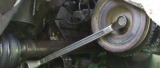
- Unscrew the spark plugs from their seats, having first removed the high-voltage wires. The elements are removed with a special key.
- Inspect the spark plugs for carbon deposits, mechanical defects, and poor clearance.
- Send defective spark plugs to a landfill and install new ones in their place.
If replacing or cleaning the spark plugs does not produce results, then the reason lies in other elements of the ignition module.
When to change?
It is difficult to say when it is necessary to replace them, but there are several reasons for which they need to be replaced. Good wires do not need to be replaced, but to understand whether the wires are good or not, they need to be inspected. When inspected, the wires should not contain:
- Scuffs;
- Cliffs;
- Cracks in insulation;
- The wire caps must be securely fixed to the spark plug and ignition module;
- The wires must be elastic and bend easily;
If one of these criteria is noticed when inspecting the wires, they must be replaced with new ones.
BB: professional replacement
If you have decided to contact the service for the process of replacing high-voltage wiring, then it is, of course, a good thing, but not worth the money that will be asked of you. They can also confuse your brain on the topic of how often high-voltage wires need to be changed, with the logic that it is better to take care of prevention in advance than to get stuck on the highway. You won’t get stuck on the highway, the contact is not a sensor, even the last one doesn’t die right away. Replacement will cost from 1000 rubles. The advantage of service in this case will be the fact that they will look at the candles for you. And they will definitely be cleaned (they tend to become oily, which negatively affects the throughput for pulses through high-voltage wires).
Symptoms of a problem
If the wires are faulty, the VAZ 2114 engine begins to operate unstably. This causes voltage leakage to the engine body, which leads to misfires.
If the wires on the car are faulty, the following problems are observed:
- When you press the gas, jerks occur and the car does not accelerate;
- When driving under load, the car jerks and does not pick up speed;
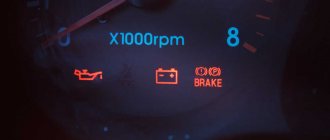
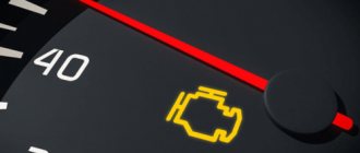
- When driving, “CHECK” flashes;
If your car has such problems, first of all you need to check the armored wires for integrity.
Cost and articles
Below are prices and articles for good and high-quality high-voltage wires for VAZ cars, both for 16 and 8 valve engines.
| Manufacturer | Number of valves | vendor code | Price, (rubles) |
| Standard | 16 | 21120-3707080-81 | 990 |
| SLON | 16 | 2112-3707080 | 1450 |
| VOLTON | 16 | VLT-2112005 | 915 |
| TESLA | 16 | Т516M | 1710 |
| LADA | 8 | 21110-3707080-82 | 695 |
| TESLA | 8 | Т514M | 875 |
| Standard | 8 | T684H | 620 |
| Original | 8 | 21110-3707080-12 | 710 |
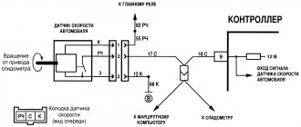
Armored wire connection diagram
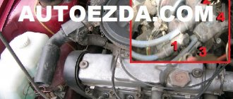
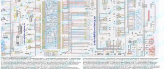
Many people, when replacing wires, wonder how to properly install new armored wires and not mix them up. If you mix up the wires, the car may not start at all, or it will start, but some cylinders will not work, so it is very important to follow the sequence of connecting the wires.
On the ignition module, where the high-voltage wires are connected, there are marks with numbers; these numbers indicate the cylinder number. The order of cylinder counting on the VAZ 2114 starts from the timing belt to the air filter housing, i.e. Cylinder number one will be near the timing belt, and number 4 will be closer to the air filter housing.
How to properly connect armored wires to a VAZ 2114 can be seen in detail in the picture below.
WHICH GDP IS BETTER TO CHOOSE?
When choosing a GDP, two key factors must be taken into account - their resistance and breakdown voltage. The lower the resistance, the better the electrical impulse will be transmitted, and the magnitude of the maximum breakdown voltage determines how resistant the high-voltage wires on the VAZ 2114 will be to breakdowns.
The resistance value of products from different manufacturers differs from each other. As an example, we give you the resistance of the most popular types of GDP:
| Manufacturer | Resistance on cylinder No. 1 (kOhm) | Resistance on cylinder No. 2 | Resistance on cylinder No. 3 | Resistance on cylinder No. 4 | Breakdown voltage (kV) |
| Tesla | 3.27 | 4.16 | 5.02 | 6.26 | 50 |
| Cezar | 3.1 | 3.53 | 4.23 | 5.34 | 50 |
| Finwhale | 1.95 | 2.18 | 2.6 | 3.42 | 50 |
| Ween | 6.17 | 6.57 | 7.52 | 9.89 | 35 |
| Slon | 4.24 | 4.74 | 5.19 | 7.6 | 50 |
The products of the Czech company Tesla receive the largest number of positive reviews from the owners of the fourteenth. Their wires have optimal resistance and high breakdown voltage, and at the same time they are truly made to last - they do not tan or crack.
The cost of the Tesla GDP set is about 500 rubles, Cezar - 450 rubles, Ween - 270 rubles, Finwhale - 600 rubles, Slon - 500 rubles.
How to check the ignition on an injector
First you need
o will conduct a full computer diagnostic of the system. If problems are found, the on-board computer ( ] - “computer”) is a device or system capable of performing a given, clearly defined, changeable sequence of operations
) will indicate them by way (
place, direction or the process of movement (or change); up to the scientific abstractions of this concept: Path - a system of communication along which passage or travel is carried out, along which
) red indication (
methods and techniques of observation, recording, control, characterization and assessment of the state and stages of development of various processes, objects and research systems to establish and control dependencies on
) “Check”.
Pushcha ( forest (indigenous forest, primary forest, primeval forest, pushcha) - a forest that has not been changed by human activity and natural disasters
) the whole reason for the breakdown (
toponym in Russia
) is not the electronic ignition module, but problems with the damper (
technique - a device for shutting off openings and pipelines: Damper - a valve for closing a chimney or ventilation duct Damper - a cover for closing the inlet of a furnace or
) throttle assembly (
a method of connecting and protecting linear material, for example, rope, by tying and weaving
).
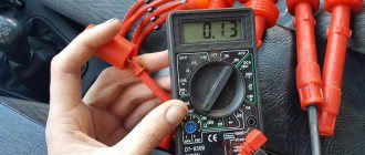
Here you will need a multimeter with which you need to measure voltage ( Electrical voltage between points A and B - the ratio of the work of the electric field when transferring a test charge from point A to B to the value of this test charge
) in a system ( a set of elements that are in relationships and connections with each other, which forms a certain integrity, unity
).
After ( high-ranking diplomatic representative of his state in a foreign state (in several states concurrently) and in an international organization; official representative
) turning the key in the ignition system, indications (
testimonies are information expressed in oral responses of witnesses about circumstances relevant for consideration and resolution of the court case
) of the device must be the following:
- total voltage of the on-board circuit is 12 V;
- The throttle valve sensor readings are 0.5 V, while the throttle valve is open only 1%.
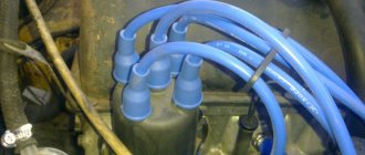
Device
Wires are made of material that has good insulation resistance, and the conductor of the wire should have low resistance for better conductivity of voltage and current.
A high-voltage wire has: insulation, a conductor, insulating caps and contact terminals. Also, some wires are equipped with a special comb, which is needed to assemble the wires into one unit.
Error codes
When diagnosing a car at a service station or if you have the appropriate equipment, you can determine some malfunctions of the ignition module.
There are several codes that will be very useful for you:
- If the coil of cylinders 1 and 4 breaks, the device will display error P0351;
- If there is a break on cylinders 2 and 3, the error code will be P0352;
- Code P3000-3004 indicates multiple misfires.
It would be a good idea to fully check the ignition module. The simplest diagnostics involves measuring the resistance between wiring of cylinders 1 and 4 and cylinders 2 and 3 with a multimeter. First switch the device to ohmmeter mode. If the indicator was 5.5 units. then everything is fine with your module.
Although there are three more ways to check:
- Check the wiring harness. Disconnect it and check with a voltmeter. The probe is directed to contact A, and the second to engine ground. Start the engine and check the indicators. A good indicator is about 12V. If there is no voltage, the coil may be faulty.
- Examine the condition of the high-voltage wires with an ohmmeter. If the high-voltage circuits are installed incorrectly, the module will simply burn out.
- Pull the block with the wires a little and tap on it. Contacts should not be lost in this case. If the opposite happens, this indicates bad contacts that can completely break off at the most inopportune moment in the very near future.
Lada 2109 › Logbook › Dual-circuit ignition on the VAZ 2109
I suffered several times in the winter with starting the engine. Even when it’s not cold, but at 0 degrees, you come to start it and the car is silent. You unscrew the damp spark plugs and the battery eventually dies! With a good battery, it starts normally. As it turned out in the end, I had a contact ignition coil B- 117 from the classics. I immediately changed it to a coil from BSZ. And the car started to start and drive much better, but I didn’t stop there and decided to make a dual-circuit ignition with 2 hall sensors, 2 switches and 2 coils from the Volga ZMZ- 406
To begin with, I started assembling the distributor because it is the most basic and thinnest part of the system. I took the distributor from OKI as a basis, or an ordinary nine-wheel one. I just had it from the window lying in the garage. I completely disassembled it and started installing the second one. hall sensor directly to the standard platform at an angle of 90 degrees. Marked the approximate position of the 2nd sensor. On the platform there are risks of the approximate position of the middle of the sensor:
Drilled and tapped the threads for the bolts:
Then I carefully cut the hall sensors themselves with a metal cloth so that they do not interfere with each other. It looks something like this:
Then I modified the shaft, replaced the ignition angle advance weights with nine-shaft ones. They are smaller and lighter than those of the Oka, the photo shows Okushinsky weights! And accordingly, I also replaced the springs. The curtain remained the standard Okushinsky one, I didn’t touch it. If you make it from a nine-shaft shaft, then the curtain must also be modified sawing off two opposite ones so that it looks like in the photo:
That's all for the shaft! Next, I cut out a small piece from the distributor body itself to attach the fork of the 2nd hall sensor, drilled a hole and cut a thread for the bolt
Then I put the whole thing together. Here’s what happened:
Note: during assembly it turned out that the platform on which the hall sensors are attached from the Oka is larger than from the 2109 and it turned out to be easier to mount the sensor, so another one +, It is advisable to buy the same sensors themselves in the same store from the same batch as they are slightly different! That's all for now with the distributor!
Then I bought the rest of the necessary parts: 2 coils from the Volga ZMZ-406, a wiring harness for the BSZ 2108, an “Astro” switch, as I already had the same one
I connected the wiring according to the diagram:
Note: when connecting according to scheme 1, the tachometer will show half the revolutions. If you want to make a normal tachometer, then there is also scheme 2, you will need to solder in 2 KD213A diodes. But I did not do this and did it according to scheme 1. And don’t try to connect wires without diodes according to scheme 2; thereby you parallel both coils and it turns out that all 4 spark plugs spark at the same time when both hall sensors are triggered! Tested personally)
I made a metal mount for the coils, but it didn’t turn out very well:
And now about the most important thing: for the system to work well, you need to adjust the synchronization of the hall sensors so that the spark on all cylinders is the same advance. To do this, you need to make the opposite mark on the flywheel, this will be the TDC of the 2nd cylinder. You need to count 64 teeth along the crown from the standard mark. And Using a strobe light, align both marks from the 1st and 2nd cylinders, moving the 2nd hall sensor up and down or both sensors in the direction of the white arrows. To do this, I drilled holes with a thin drill in the sensors to move.
General tips for connecting high-voltage wires.
Checking high-voltage wires. To check the wires, you will need a multimeter tester. Check the resistance of the wires - it should be no more than 20 KOhms (in practice, the longest wire of cylinder 1 has a resistance of up to 10 KOhms). If the wire resistance is more than 20 Kom, it must be replaced. Carefully inspect the wires for chafing on parts of the motor or other wires. In case of significant abrasion, replace the wire. In case of minor abrasion, it is possible to lay the wire so that it does not rub and fix it in this position.
Location of high voltage cables.
If you recently bought a new car, then you don’t have to think about the location of high-voltage cables. But after a while, due to the aging of materials, the reins begin to “foul.” This reduces sparking power and can cause problems with electronic control systems. Therefore, if you notice bright glows in the area of lugs or wires, try moving the cables with a dry wooden pole, achieving minimal glow. You don’t need to do this with your hands, it will hurt from the electric shock, but it’s better to contact a service center to have your car’s ignition system repaired.
Why shouldn't you repair the ignition system yourself? You need a tool, knowledge of car electronics, experience and time. Contact special services that value their time and yours, although they do not do anything on the cheap, that is, cheaply.