I want to relieve the power part of the switch by installing an additional one from the basin 2108. I bought 0529.3734 with a connector. I found information on the Internet about AZLK, cadet C16NZ, digested it, summarized it and drew it beautifully and clearly. All that remains is to test)
Brief description: The high cost of native switches and the impossibility of finding them in the village / on the road makes you think about installing a switch from the basin. They cost 300 rubles and can be found in any general store. And if you make connectors, you can return to your native one in 5 seconds. So what do we do. We leave the adjustment of the OZ to the native switch. And we’ll entrust spark control to a new one. We remove the signal for adjusting the OZ from D and hang it on the 6th leg.
Theory of our ignition system:
A magnetoelectric sensor is built into the ignition distributor, which generates control pulses and supplies them to the input of the electronic ignition unit. The sensor consists of a rotor with permanent magnets and an inductive coil. When the magnetic pole of the rotor passes past the inductive coil, an alternating voltage is induced in the latter. The electrical signal from the coil is fed to the input of the semiconductor unit, which generates current in the primary circuit of the ignition coil (high-voltage transformer). During certain phases of voltage change in the inductive coil circuit, a sharp decrease in the current in the primary circuit of the ignition coil occurs. In this case, a high voltage is generated in the secondary winding of the ignition coil, which is supplied by the ignition distributor to the spark plugs in the order of operation of the engine cylinders. A capacitor is located in the distributor to reduce interference to radio reception. The ignition timing is adjusted by the engine ECU based on signals from various sensors that control the engine operating mode.
Adjusting the initial ignition timing
The non-contact ignition system is designed for forced ignition of the working mixture compressed in the engine cylinder. Ignition of the mixture is achieved using a spark between the electrodes of the spark plug. High power performance and good fuel efficiency of the engine while reducing the amount of harmful emissions into the atmosphere with exhaust gases are ensured by an electronic ignition timing control system (IAC), which is controlled by the engine ECU. In order to calculate the ignition timing, the ECU must monitor various parameters: – crankshaft speed; – engine load (vacuum in the intake manifold); - Atmosphere pressure; – engine coolant temperature; – formation of a high voltage reference signal. This signal allows the ECU to calculate the rotation speed and angular position of the crankshaft; – formation of a low voltage reference signal. The corresponding wire is connected to ground in the ignition unit. The presence of voltage may interfere with the normal operation of the ignition system. Therefore, a break in this wire can lead to a deterioration in the performance of the SRZ and a decrease in engine power; – shunt control. When the crankshaft rotation speed reaches about 400 rpm, the ECU supplies a 5 V control voltage to terminal SZ to switch the ignition timing control function from the ignition unit to the ECU. If there is a short to ground or a wire break, the ECU sets fault code 42 and transfers the function of regulating the ignition timing to the ignition unit. In this case, the engine operates with the initially set ignition timing plus a small advance angle included in the operating algorithm of the ignition unit. – generation of an ignition timing control signal. Through terminal D10 and the corresponding wire, the ECU transmits control pulses to the ignition unit. The ECU does not determine the absolute value of the ignition timing. It calculates only the correction relative to the initially set (base) ignition timing value and supplies control signals that are slightly retarded or ahead of the reference signal received from the ignition unit. For this reason, incorrect initial setting of ignition timing leads to a general shift in ignition timing in all engine operating modes. A break or short to ground in the signal wire of the SRZ leads to the issuance of fault code 42 and the shutdown of the SRZ. In this case, the advance angle is set by the ignition unit without the participation of the ECU. When adjusting the ignition timing, the ECU processes the signals from the intake manifold pressure (MAP) and coolant temperature (TCT) sensors. The ECU operation algorithm provides for: -• increasing ignition timing at low DBP signal voltage and at low coolant temperature; • - reduction of ignition timing at high voltage of the DBP signal and at high coolant temperature. Therefore, detonation, as a rule, occurs when the voltage of the DBP signal is low or when the electrical resistance of the DTG thermistor is high. A decrease in engine power can be observed when the DBP signal voltage is high or when the electrical resistance of the DTZ thermistor is low.
A command is received via the “shunt” wire to turn off the SPD adjustment (after closing contacts A and B). After this, the initial OZ is set. Shunting is usually short-circuiting with less resistance.
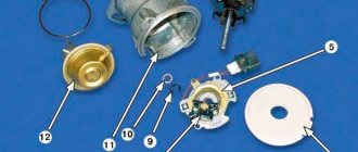
The switch is an electronic component to ensure the operation of a contactless ignition system. It is transitional between contact and microprocessor. The latter, the most advanced, allows you to control the torque using data read from sensors - oxygen, speed, engine speed and others. But there are still many cars on the roads that have both contact breakers and contactless ones. Therefore, for maintenance and diagnostics, you need to know the purpose of all elements, as well as troubleshooting methods and their main symptoms. Before testing the switch, review all parts carefully.
Contactless ignition system
In total, there are three huge groups of systems - contact, contactless, microprocessor. The first is divided into two subgroups - contact and using a transistor operating in switch mode. Transistors are also used in the design of a contactless ignition system. This scheme began to be actively used in the early 80s of the last century. And it has a number of advantages, which will be discussed below. The switch circuit is simple; it can be implemented both on transistors and on a controller.
Replacing the distributor (ignition distributor) on a VAZ 2108-VAZ 21099
Direct replacement
Removal
1) First, de-energize the engine system by disconnecting the negative terminal from the battery.
2) Next, disconnect the high voltage wires from the distributor cover.
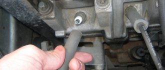
3) Remove the vacuum hose from the vacuum regulator fitting.
4) Then completely unscrew the top nut securing the distributor and wire holder.
5) Remove the holder from the car engine.
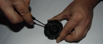
6) Use your hands or a screwdriver to disconnect the wire block from the distributor.
7) Now unscrew the two remaining nuts that secure the distributor at the bottom: use a wrench to unscrew the left nut of the distributor.
Then unscrew the right nut.
 Remove the distributor directly from the engine of the car.
Installation: 1) First, remove the two screws from the cover and remove it.
2) Then turn the slider with strictly outer contact opposite the “first cylinder” terminal located on the cover.
3) Install the distributor in the reverse order of removal.
4) Place the negative terminal on the battery and set the initial ignition timing.
Changing the cover
1) First, disconnect all high-voltage wires from the cover.
2) Then use a Phillips screwdriver to remove the screws holding the plastic cover to the distributor.
3) Remove the cover and replace it with a new one.
Note! The cover on the distributor is installed in only one position. And the high voltage wires are put on the cover in the order: 1-3-4-2. There is a marking “1” on the distributor cover itself, start counting from there in order, counterclockwise.
Replacing the slider:
1) First, remove the cover according to the instructions described above.
2) Next, remove the slider from the shaft by pulling it with your hand.
Note! The slider is installed in its place only in one position, when the slot on the shaft is directed in the opposite direction from the contact!
Main elements of the system
Of course, the first thing to mention is the spark plugs. They are installed in the cylinder head, the electrodes come out from the inside. These are the elements that allow the air-fuel mixture to ignite. But with the help of spark plugs alone, the engine will not be able to run. It is necessary to monitor the position of the crankshaft in order to know in what position the pistons are in the cylinders.
For this purpose, an inductive sensor operating on the Hall effect is used. It is part of the design of another element - the ignition distributor. The sensor produces a pulse that is sent to the switch. This device allows you to amplify a weak signal to a voltage of 12 volts, and then apply it to a coil. A coil is nothing more than a simple transformer (step-up). Its secondary winding has a greater number of turns than the primary. Due to this, the voltage increases and the current decreases. The voltage in the BSZ is supplied to the spark plugs at a value of 30-35 kV (depending on the car model).
Replacement of distributor and its parts on VAZ 2108, VAZ 2109, VAZ 21099
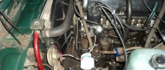
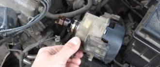
Distributor location: Located next to the battery, at the end of the cylinder head cover. See the photo below for more details:
When to change the distributor? It fails quite rarely; most often the distributor parts, such as the slider, distributor cover and others, must be replaced. Below is a list of malfunctions that occur in the engine when the distributor or its components fail:
- the car starts to jerk;
- the car simply won’t start;
- loss of power from the car engine, the car drives worse;
- increase in vehicle fuel consumption.
How is BSZ better than contact?
Having carefully read the previous section, you can see that the system uses an inductive non-contact Hall sensor. The advantage is obvious - there is no friction and commutation. For comparison, look at the contact system. In it, the breaker switches the voltage, the value of which is 12 Volts. Whatever one may say, the metal contacts are constantly in contact with each other, gradually wear out, and become covered with soot.
For these reasons, it is necessary to constantly monitor the breaker, adjust the gap, and carry out timely replacement. BSZ is devoid of these shortcomings, therefore, without third-party intervention, the system operates much longer. The Hall sensor fails very rarely, as does the switch. This increases the reliability of the system, but precautions must also be taken, in particular, the connection of the switch to the body must be as tight as possible to ensure effective heat exchange. In addition, BSZ allows you to improve engine performance, increase, albeit slightly, its power, along with increasing reliability.
Replacing the distributor
Before you begin to remove the distributor (ignition distributor) on the VAZ 2109-2108, you must disconnect the negative terminal from the battery. This procedure is not as difficult to perform on your own as it might seem, but there are very important points that are worth paying attention to.
This will be discussed in detail during the description of the procedure. To perform this repair you will need the following tools:
- 10 open-end wrench or socket wrench
- Socket head and ratchet handle
- Phillips blade screwdriver
The procedure for removing and installing the distributor on a VAZ 2109-2108
So, before you begin removal, pay attention to the installation position of the distributor relative to the body. Be sure to remember or mark it so that when installing it, put it in the same position.
distributor position marks on VAZ 2109-2108
Then you need to disconnect the high-voltage wires from the distributor cap: 4 spark plugs and one central one from the ignition coil: disconnecting high-voltage wires from the distributor on a VAZ 2109-2108
It is also necessary to disconnect the plug with wires, which is clearly shown in the photo below: disconnecting the plug of wires from the distributor on a VAZ 2109-2108
Then we pull off the thin hose from the distributor vacuum corrector: disconnecting the hose from the distributor vacuum corrector on a VAZ 2109-2108
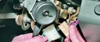
Now you can proceed directly to unscrewing the nuts securing the VAZ 2109-2108 distributor itself. There are three of them in total: one is located in the center at the top: nuts for fastening the distributor on the VAZ 2109-2108
And the other two are located on the sides, and it is more convenient to unscrew them with a regular open-end wrench, since a ratchet with a head simply cannot get there. Do not unscrew the side ones completely yet, as you need to set the TDC marks.
But before removing the ignition distributor, it is necessary to install the piston of the 1st cylinder at TDC. To do this, through the hole in the gearbox housing (after removing the rubber plug), you need to align the marks on the housing and the flywheel. With the gearshift lever in the neutral position, use a 19mm key to turn the crankshaft pulley to the required torque. This is what it should look like: setting timing marks on a VAZ 2109
And only after this we unscrew the two remaining nuts and begin to remove the distributor, removing it from the studs to the side: replacing the distributor with a VAZ 2109-2108
If you decide to replace the distributor, then you need to buy a new one, the price of which for VAZ 2109-2108 cars is about 1000 rubles. Before installation, you must remove the cover by unscrewing the two bolts securing it: remove the distributor cover on the VAZ 2109-2108
And when you put it in place, make sure that the outer contact of the slider during installation is exactly opposite the output of the first cylinder on the cover: installing a distributor on a VAZ 2109-2108
That is, after the distributor has been placed on the housing studs, lean the cover and see if the contact position of the runner coincides with the output of the 1st cylinder: correctly set the position of the distributor runner on the VAZ 2109-2108
And after that, we finally tighten all the nuts securing the distributor and install the cover in its place. And do not forget that it is necessary to maintain the original position of the distributor relative to the body in order to maintain ignition timing.
How does a switch work?
Essentially, a switch is a simple signal amplifier. It can even be compared to a Darlington assembly, which is used in microcontroller technology to convert a weak signal from an output port to the required level. The basis of this assembly is field-effect transistors operating in switch mode. An operating voltage is applied to them, a signal is sent to the control terminal, which is amplified and removed from the collector.
The ignition switch has an almost similar operating scheme. Only the signal from the Hall sensor is used. It has three outputs - control, common, plus power. When a metal plate appears in the sensor area, a current is generated, which is supplied to the input of the switch. Next, the signal is amplified and supplied to the primary winding of the coil. The entire system is powered only after the ignition is turned on (after turning the key).
How to check the ignition coil of a VAZ
If the ignition coil is faulty, the engine will not start. A characteristic sign of a faulty coil is its increased temperature when the ignition is turned off. This is easy to determine by touch.
Signs of a faulty ignition module may include the following:
- hesitant engine starting or failure to start;
- failures during sudden changes in speed;
- high fuel consumption;
- two cylinders do not work, the engine is feverish;
- lack of dynamics;
- a sharp drop in power;
- drop in power and thrust after warming up.
These symptoms may not only be caused by the ignition module. To determine the malfunction, it is enough to spend a few minutes diagnosing spark plugs, high-voltage wires and caps. This will eliminate the remaining elements of the ignition system and make sure that it is the ignition module that is faulty.
Checking the ignition coil is performed in one of 2 ways. The simplest one is to remove the central wire from the breaker-distributor, bring it to the motor housing and turn it with the starter, and a running spark should appear. After this, we check the energy supply to a separate spark plug, for which we unscrew the working spark plug, bring its contact to ground and attempt to start the engine. In this case, the spark should come from the wire to ground. If it is absent, the reason will be a malfunction of a system element such as the ignition coil.
To check the module in the second way, we only need a multimeter, then follow the step-by-step instructions:
- We check the power supply and the presence of pulses supplied from the ECU. We check the power between the central terminal (15) of the wire block connected to the module and the engine ground. When the ignition is on, the voltage should not be less than 12 V. Otherwise, either the battery is dead or the ECU does not work.
- We check the pulses from the ECU on the wiring block. We install one tester probe on connector 15, the second on the far right, then on the far left. The assistant cranks the engine with the starter, and at this time we record short-term voltage surges with a tester. If there are no impulses from the ECU, it is he who is to blame.
- We check the resistance on the secondary windings of the coils. We put the tester in resistance measurement mode and measure it at the high-voltage terminals of the module cover. Between pins 1 and 4 and pins 2-3, the resistance should be 5.4 kOhm. Otherwise, the module must be replaced.
- We check the resistance of the primary windings between contacts 15 and the rightmost, then the leftmost terminals. Nominal - 0.5 Ohm. Deviation is not allowed.
- Check the module for a short circuit. In ohmmeter mode, install one multimeter probe on the central terminal, the second on the metal body. There shouldn't be any resistance. If the device detects at least some resistance (other than unity or infinity), the module must be replaced.
Basic Switch Elements
The switch circuit is quite simple, but making this unit yourself is pointless, since buying a ready-made version will be much easier. Installation must be carried out as competently as possible, otherwise the device will not operate correctly. In addition, when using transistors, you need to carefully select them according to their parameters, and for this you need to have high-quality measuring equipment. Unfortunately, for two identical semiconductors, the spread of characteristics can be very large. And this affects the operation of the device.
The VAZ switch, designated 76.3734, consists of one main element - the L497 controller. It is designed specifically for use in contactless ignition systems. The domestic analogue of this controller is KR1055HP2. Their parameters are almost identical, which allows you to use any of the controllers. In addition, this chip allows you to connect a tachometer located on the dashboard of the car. But you can also use a simpler circuit, which is an amplifier unit of two stages. True, the reliability of such a device is much lower.
Switch Specifications
The VAZ switch circuit is based on the L497 microcircuit, which controls the output NPN transistor. A special feature of the microcircuit is the ability to program the recovery time of the delay coefficient, which is important for trouble-free starting of a cold car power unit. This feature of this electronic component of the switch allows for rapid acceleration of the crankshaft speed without failures in operation, which ensures constant engine traction.
Analogues that are sometimes used in the design of the VAZ 2108 switch are the KR1055HP1, KR1055HP2, KR1055HP4 microcircuits. However, these electronic components are found quite rarely in the design of the device. Main technical parameters of the device:
- optimal operating voltage 13.5 V;
- voltage range for normal operation 6-16 V;
- switching current 7.5-8.5 A;
- the range of ensuring uninterrupted sparking is from 20 to 7000 crankshaft revolutions.
The design of the device is designed for use in single-wire power circuits on cars in which the body plays the role of a negative terminal. Installation of a device mounted on the L497 chip is carried out in a specially designated place using standard fasteners.
Connecting the switch
Cases vary, and it is possible that you will have to change the wiring. Therefore, you will need to take into account the purpose of all pins on the switch plug. This will allow the connection to be made correctly, and there will be no risk of damaging it. The first pin of the switch is the output. In other words, the amplified signal is removed from it. It must be connected to the terminal of the “K” coil. The second contact is connected to ground - the negative of the battery.
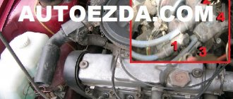
All three wires from the Hall sensor go to the VAZ switch. Moreover, the signal wire is connected to the sixth terminal of the switch. The fifth is the power output (the voltage on it is stable 12 Volts). The third output of the switch is ground (minus power). The third is connected inside the block to the second. But between the fourth, which is supplied with power from the battery, and the fifth there is a constant resistance and a voltage stabilizer.
How to recognize switch faults
Ignition problems are always accompanied by characteristic symptoms that every car owner should be aware of. One of these faults is related to the switch.
Here are just the most common signs indicating problems with the operation of the VAZ 2108 switch.
- The engine cannot be started.
- The starter actively turns the engine flywheel, but there is no spark.
- The engine can be started, it idles, it can be raised to medium speeds, but it is impossible to increase the speed to maximum.
- The motor is not running at full power.
- At idle, the engine runs fine, but begins to stall when trying to start.
- The engine can be started, but it stalls after a short time.
- One of the cylinders refuses to work at a certain speed (troit).
- The engine stalls when hot and continues to run normally when it cools down.
- The battery discharge lamp is on.
- The tachometer shows sharp jumps in engine speed.
How to check
There is nothing complicated in this procedure. The easiest way is to use a known-good node, since you can check the switch this way in literally a matter of minutes. But if there is none, and you need to determine exactly whether the fault is in the coil or in the switch, it is wiser to use other methods. You will need a simple incandescent lamp. If you don’t know where to get it, then unscrew it from the interior lamp or from the side lights.
Connect one terminal of the lamp to the negative of the battery. Connect the second one to pin “1” of the switch. This is the same pin from which the amplified signal is removed. If the lamp lights up, then the device is working properly. A more advanced testing method is carried out using an oscilloscope. On the screen you can see the magnitude and shape of the signal, and also compare it with the reference one.
What is BSZ and how does it work?
To successfully install and configure contactless ignition, it is advisable to understand the operating principle of the system, which consists of the following elements:
- Main ignition distributor (otherwise known as distributor). Inside it is installed a photoelectric Hall sensor, a vacuum drive for adjusting the advance angle and a so-called slider with a moving contact.
- A coil that produces a high voltage pulse. It has 2 windings: a primary winding, consisting of a small number of turns of thick wire, and a secondary winding, wound with a thin wire with a large number of turns.
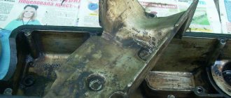
- The electronic unit is a switch equipped with an aluminum cooling radiator. The latter plays the role of a fastening element.
- Spark plugs connected by high-voltage wires to the distributor.
- Wires for connecting elements to each other.
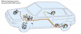
Scheme of operation of the BZS VAZ 2107
The first contact of the coil is connected through the ignition switch relay to the generator, and the second to the control unit. Also, a high-voltage wire with a large cross-section goes from it to the distributor. There are 2 bundles of wires coming out of the distributor, connecting it to the switch and spark plugs. The system operates according to the following algorithm:
- After turning on the ignition by turning the key in the lock, a voltage of 12 V is applied to the primary winding of the coil, which creates an electromagnetic field.
- When the crankshaft rotates and one of the pistons reaches top dead center (TDC), the photoelectric sensor sends a signal to the switch, which briefly breaks the connection between the coil and the voltage source - the generator or battery.
- During a circuit break, a voltage pulse of 20 to 24 kV is generated in the secondary winding of the coil, transmitted through a large cross-section wire to the distributor slider.
- The movable contact of the slider directs the impulse to the spark plug where the piston reached TDC. A powerful spark jumps between its contacts, igniting the mixture of fuel and air in the combustion chamber.
- The distributor shaft is driven by a gear transmission connected to the crankshaft. When the next piston moves to TDC, the shaft rotates and the moving contact connects to another spark plug, and the Hall sensor sends the next signal and the sparking cycle is repeated.
Ignition settings
When setting up the ignition, you will need to do the most important thing - install the shafts according to the marks so that the gas distribution functions synchronously with the operation of the piston group. This is the first thing you should do before you start adjusting the ignition. It is worth noting that there should not be any particular difficulties during setup, especially on VAZ 2108-21099 cars. The thing is that the ignition distributor on the engines of these machines can only be installed in one position. Moreover, the ignition switch does not undergo any settings during this procedure, since it does not have any.
The distributor body rotates around its axis to make more precise adjustments. And this turns out to be enough. To accurately set the torque, you can use a simple circuit that uses a simple LED as an indicator. The Hall sensor is disconnected from the system, and positive power is supplied to its negative terminal. An LED is switched on between “+” and the signal LED, and a 2 kOhm resistance is connected in series with it to reduce the voltage. But the plus of the Hall sensor is connected to ground. Now all that remains is to slowly rotate the distributor housing. The moment when the diode lights up will be the desired one.
Other ways to test your switch
Despite the relatively low cost of a new switch, car enthusiasts do not always have the desire, and sometimes even the opportunity, to purchase it.
And even if the old switch is in good working order, replacing it will in no way affect the operation of the engine.
This is why many owners of VAZ 2109 cars prefer to check the old switch before replacing it with a new one.
Rice. 4 Mounting the switch on the car body.
This unit can be professionally checked at a service station using a specialized stand.
Professional equipment can show not only the presence or absence of an impulse from the switch to the ignition coil, but also their cyclicity and stability.
But not all service stations have such equipment, so craftsmen have come up with another simple way to check the switch.
For this test you will need an 8 wrench and a 12 V 3 Watt test light. The procedure is as follows:
- Remove the negative terminal from the battery.
- Using a size 8 wrench, disconnect the brown wire from the terminal marked “K” on the coil, which goes to the terminal marked “1” of the switch.
- Connect one end of the 12 V test lamp contact to this wire, and the other to the terminal marked “K” on the coil. Thus, the test lamp should be in the circuit between the coil and the ignition switch.
- Put the battery terminal back on.
- Try starting the engine. While the starter is rotating, the warning light should be on. If this does not happen, then the switch is not working and needs to be replaced.
You may be interested in:
Schematic electrical diagrams, connecting devices and pinouts of connectors
Today we will look at the design and diagrams of ignition systems for VAZ cars of all major models. Since carburetor versions of VAZ are practically history, we will dwell in detail on the ignition systems of injection cars. Their ignition system is based on an electronic ignition module. We also recommend that you carefully consider the choice of spark plugs and the quality of high-voltage wires, because the quality of the spark and, accordingly, the operation of the ignition system as a whole will depend on them. The information is intended as a reference guide for self-repairing a car.
conclusions
Many advantages are provided by such a simple unit in a contactless ignition system as a switch. This includes an increase in power, even if only slightly, a reduction in fuel consumption, and a significant improvement in the engine in terms of reliability. And most importantly, there is no need for constant monitoring and timely adjustment of the system. The modern driver does not want to repair a car, he needs a means of transportation. Moreover, it is reliable and will not let you down at the most crucial moment. Regardless of which switch is used in the BSZ, its efficiency is much higher than that of a contact breaker.
Types of switches
When reviewing the main types of switches, it is necessary to mention that modern systems are endowed with a number of significant advantages, thanks to which these devices have increased efficiency and reliability. Such indicators were achieved by using microprocessor units in the design. Today, the automotive market offers a variety of models, including dual-channel and multi-channel switches. Depending on the parts used in the design, these devices are divided into several types:
Transistor. They use a contact system, which reduces their service life due to rapid wear of elements due to burning. The energy is stored in the electromagnetic field of the coil.
Thyristor. The main difference from the first type is that in these devices the creation of the required current occurs in a capacitor. When the system is turned on, a charged capacitor is connected to the coil winding. A vacuum occurs inside them, which leads to a spark at the spark plug.
Hybrid. This type of switches is very popular. It is a tandem of several types described above. This design solution improves efficiency and minimizes disadvantages.
Contactless devices are considered the most effective systems. This type represents the most modern switches, which are significantly superior in parameters to other types. Their design uses infrared electronic sensors. The absence of a contact ignition method ensures a long service life, since there are no segments on the surface of which carbon deposits accumulate. On domestic cars, this ignition system was first introduced on VAZ-2108 models.
Techno lovers site
Since an idea appeared on the Internet about the possibility of using the 3620.3734* switch instead of the standard Tavria 1102.3734/1103.3734, I decided to post an article on repairing them, along with the diagrams of these switches. The original article is here, but for some reason the developer of this web page posted the pictures separately from the article. It’s very inconvenient, I’ll translate it in human terms:
When the electronic ignition switch in your car fails, as a rule, you either buy a new one, since there is no way to check its functionality due to the lack of specialized service centers, or take it to local craftsmen who try it using the “scientific poke” method repair. Most operating instructions do not contain a description of the troubleshooting technique, so we provide a complete troubleshooting technique and circuit diagrams of the most common electronic ignition switches.
Ignition systems for gasoline engines of domestic passenger cars VAZ-2108, VAZ-2109, ZAZ-1102 contain an electronic switch. It is designed to generate current pulses in the circuit of the primary winding of the ignition coil.
In domestically produced electronic switches (series 3620.3734; 36.3734; 78.3734), the functions of the output current switch are performed by a powerful transistor, and the functions of controlling the parameters of current pulses (normalizing the duty cycle of triggering pulses, software regulation of the time of energy accumulation in the ignition coil, limiting the current level in its primary winding and amplitude of primary voltage pulses) is performed by a low-current electronic circuit, often in an integrated design.
The first domestic electronic switch with controlled parameters of ignition pulses (series 36.3734) was developed for the VAZ-2108 car. The switch used the K1401UD1 microcircuit, a powerful key transistor KT848A and other domestically produced elements.
The input information signal for the switch is the signal from the Hall sensor located on the ignition distributor shaft. Using this signal, the switch receives information about the number of engine revolutions and the position of its crankshaft. The switch is designed to work with a serial ignition coil 27.3705. The switch was a prototype for the development of subsequent series, which have several design and circuit design options. However, what domestic switches still have in common is a combined integrated-discrete assembly technology, which makes them repairable.
Modern domestic switches use specialized output key transistors of the types KT890A, KT898A1, BU931 (foreign) in several designs: TO-220, TO-3, unpackaged. Some switches, for example 78.3734 (Fig. 4), use a four-channel operational amplifier of the K1401UD2B type as a control chip.
The switches also widely use the L497B control chip from SGS-TOMSON (domestic analogue of the P1055HP1). The block diagram and the recommended option for its inclusion are shown in Fig. 1, and the assignment of the pins is in table. 1.
Control chip L497B from SGS-TOMSON (domestic analogue of P1055ХП1). Block diagram and recommended option for its inclusion.
| Pin no. | Purpose | Pin no. | Purpose |
| 1 | General | 9 | Terminal for connecting the capacitor to the protection unit |
| 2 | General (signal) | 10 | Pin for connecting a storage capacitor to the delay control circuit |
| 3 | Meal 1 | 11 | Pin for connecting the correction capacitor to the delay control circuit |
| 4 | Not used | 12 | Pin for connecting an external voltage reference resistor |
| 5 | Hall sensor signal input | 13 | Current limiter input |
| 6 | Pulse Width Modulator Output | 14 | Output signal for driving an external transistor |
| 7 | Output for connecting an additional zener diode | 15 | Output pulse amplitude limiter input |
| 8 | Output for connecting the driver time constant correction capacitor | 16 | Power supply 2 (output stage) |
Before you begin troubleshooting and repairing the electronic switch, you should:
- check the integrity of the vehicle wiring, the reliability of the contact connections of the ignition system, the serviceability of the ignition system elements (spark plugs, ignition coil, Hall sensor, high voltage wires);
- check the serviceability of the car generator, as well as its integrated voltage regulator;
- check the supply of voltage from the on-board network (with the ignition switch on) to contact “P” of the Hall sensor connector.
The signs that indicate malfunctions of electronic switches, the most likely causes of these malfunctions and methods for eliminating them are summarized in table. 2.
What is the switch on VAZ 2108 cars?
This element in the operation of a car is an electronic unit that, receiving signals from a special magnetic induction sensor (also known as a Hall sensor), controls the operation of the ignition system. The schematic diagram of the device will not particularly worry us, because if the switch breaks down, it is simply replaced with a new one; it is much more important to understand how it works and, most importantly, how to diagnose it if necessary. But first things first.
The VAZ 2108 switch is connected directly to the ignition key, through which it is powered from the vehicle electrical network. The operating diagram of the device also assumes a direct electrical connection with the ignition coil and the spark plug distributor. The task of the automobile switch is to regulate the operation of automobile spark plugs through the ignition distributor using control signals from the sensor.
Setting up SZ
If you have a VAZ 2109 carburetor, you will have to adjust the ignition system from time to time. This procedure is not the simplest; it requires following clear instructions. The operating procedure is as follows:
- We take the manual for our “nine” in our hands, set the contact gaps in accordance with the recommended values. Typically this is 0.45 mm.
- The ignition timing is set using special equipment, we miss this point.
- We connect the high-voltage wires and begin adjusting the torque in the middle of the stroke.
- Install the spark plug in the first cylinder and turn on the ignition.
- Turn the pulley counterclockwise 45°.
- We connect the ground to the spark plug, turn the pulley gradually in a clockwise direction until a spark appears between the electrodes.
- We look at the marks of the cover and pulley. They must be on the same level.
- To ensure that the marks coincide, we turn the distributor in the desired direction.
- If the marks do not match, the ignition will either be late or turn on prematurely, which is unacceptable.
- We rotate the pulley and distributor until we get the desired result, after which the distributor will need to be tightened, and then turn the crankshaft two turns.
- Check the result: if everything works fine, we finish the adjustment.
- You need to warm up the engine, then drive at a speed of 40-50 km/h, switch to fourth gear and accelerate sharply. If there is a knock, the ignition worked prematurely, we adjust it again.